EP1496651A1 - Kommunikationssystem, in dem kommunikationssystem verwendete servervorrichtung, kommunikationsvorrichtung, sowie ein programm zur ausführung eines kommunikationsverfahrens der kommunikationsvorrichtung - Google Patents
Kommunikationssystem, in dem kommunikationssystem verwendete servervorrichtung, kommunikationsvorrichtung, sowie ein programm zur ausführung eines kommunikationsverfahrens der kommunikationsvorrichtung Download PDFInfo
- Publication number
- EP1496651A1 EP1496651A1 EP20030725656 EP03725656A EP1496651A1 EP 1496651 A1 EP1496651 A1 EP 1496651A1 EP 20030725656 EP20030725656 EP 20030725656 EP 03725656 A EP03725656 A EP 03725656A EP 1496651 A1 EP1496651 A1 EP 1496651A1
- Authority
- EP
- European Patent Office
- Prior art keywords
- communication
- destination information
- information
- server device
- communication destination
- Prior art date
- Legal status (The legal status is an assumption and is not a legal conclusion. Google has not performed a legal analysis and makes no representation as to the accuracy of the status listed.)
- Withdrawn
Links
Images


Classifications
-
- H—ELECTRICITY
- H04—ELECTRIC COMMUNICATION TECHNIQUE
- H04W—WIRELESS COMMUNICATION NETWORKS
- H04W60/00—Affiliation to network, e.g. registration; Terminating affiliation with the network, e.g. de-registration
- H04W60/04—Affiliation to network, e.g. registration; Terminating affiliation with the network, e.g. de-registration using triggered events
-
- H—ELECTRICITY
- H04—ELECTRIC COMMUNICATION TECHNIQUE
- H04L—TRANSMISSION OF DIGITAL INFORMATION, e.g. TELEGRAPHIC COMMUNICATION
- H04L61/00—Network arrangements, protocols or services for addressing or naming
-
- H—ELECTRICITY
- H04—ELECTRIC COMMUNICATION TECHNIQUE
- H04L—TRANSMISSION OF DIGITAL INFORMATION, e.g. TELEGRAPHIC COMMUNICATION
- H04L61/00—Network arrangements, protocols or services for addressing or naming
- H04L61/09—Mapping addresses
- H04L61/10—Mapping addresses of different types
-
- H—ELECTRICITY
- H04—ELECTRIC COMMUNICATION TECHNIQUE
- H04W—WIRELESS COMMUNICATION NETWORKS
- H04W8/00—Network data management
- H04W8/02—Processing of mobility data, e.g. registration information at HLR [Home Location Register] or VLR [Visitor Location Register]; Transfer of mobility data, e.g. between HLR, VLR or external networks
- H04W8/04—Registration at HLR or HSS [Home Subscriber Server]
-
- H—ELECTRICITY
- H04—ELECTRIC COMMUNICATION TECHNIQUE
- H04W—WIRELESS COMMUNICATION NETWORKS
- H04W8/00—Network data management
- H04W8/02—Processing of mobility data, e.g. registration information at HLR [Home Location Register] or VLR [Visitor Location Register]; Transfer of mobility data, e.g. between HLR, VLR or external networks
- H04W8/08—Mobility data transfer
- H04W8/14—Mobility data transfer between corresponding nodes
-
- H—ELECTRICITY
- H04—ELECTRIC COMMUNICATION TECHNIQUE
- H04W—WIRELESS COMMUNICATION NETWORKS
- H04W80/00—Wireless network protocols or protocol adaptations to wireless operation
- H04W80/04—Network layer protocols, e.g. mobile IP [Internet Protocol]
Definitions
- the present invention relates to a communication system and the like including mobile terminals.
- Mobile IP Internet Protocol
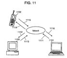
- Fig. 11 Mobile IP (Internet Protocol) is known as the first communication technology in a conventional communication system including mobile terminals. This technology will be described by using the communication system of Fig. 11.
- the communication system of Fig. 11 includes fixed terminal 1101, mobile terminal 1102, and server device 1103.
- server device 1103 has a function of getting the information of IP address even when mobile terminal 1102 moves to the space that the different network is used.
- fixed terminal 1101 transmits a communication packet to server device 1103 via path 1111 and path 1112 in Fig. 11 to communicate with mobile terminal 1102.
- the communication packet is transmitted from server device 1103 to mobile terminal 1102 via path 1113 and path 1114 in Fig. 11.
- mobile terminal 1102 directly transmits a communication packet to fixed terminal 1101 via path 1115 and path 1116 in Fig. 11.
- Fig. 11 the function of controlling the paths in server device 1103 is called a home agent.
- the function of controlling the paths in mobile terminal 1102 is called a foreign agent.
- an exclusive line is usually employed for the network between path 1115 and path 1116 in Fig. 11.
- FIG. 12 A communication system using this communication technology is shown in Fig. 12.
- the communication system of Fig. 12 includes fixed terminal 1201, mobile terminal 1202, and server device 1203.
- this communication system suppose a phone call is made from fixed terminal 1201 to mobile terminal 1202 by using IP address.
- server device 1203 has a function of getting the information of IP address even when mobile terminal 1202 moves to a space of different network.
- Fixed terminal 1201 transmits a communication packet to server device 1203 via path 1211 and path 1212 in Fig. 12 communicate with mobile terminal 1202.
- the communication packet is transmitted from server device 1203 to mobile terminal 1202 via path 1213 and path 1214 in Fig. 12.
- mobile terminal 1202 transmits a communication packet to server device 1203 via path 1215 and path 1216 in Fig. 12. Further, server device 1203 transmits the communication packet to fixed terminal 1201 via path 1217 and path 1218 in Fig. 12. In the second conventional technology, server device 1202 maintains the IP address of fixed terminal 1201 and mobile terminal 1202.
- the third communication technology is a technology for communication between a mobile terminal and a mobile terminal.
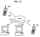
- FIG. 13 A communication system using this communication technology is shown in Fig. 13.
- This communication system includes first mobile terminal 1301, second mobile terminal 1302, first server device 1303, and second server device 1304.
- the communication packet transmitted from first mobile terminal 1301 is transmitted to first server device 1303 via path 1311 and path 1312 in Fig. 13.
- the communication packet is transmitted from first server device 1303 to second server device 1304 via path 1313 and path 1314 in Fig. 13.
- the communication packet is transmitted from second server device 1304 to second mobile terminal 1302 via path 1315 and path 1316 in Fig. 13.
- the communication packet is transmitted from first mobile terminal 1301 to second mobile terminal 1302.
- the communication packet In communication packet transmission from second mobile terminal 1302 to first mobile terminal 1301, the communication packet follows the paths in the opposite direction to the above.
- first server device 1303 serves to control the IP address of second mobile terminal 1302, and second server device 1304 serves to control the IP address of first mobile terminal 1301.
- First server device 1303 and second server device 1304 may be one unit (server device).
- the server device accesses the network every communication made by each terminal. Accordingly, the communication traffic between server device and network will become massive, and it may cause congestion.
- the communication system of the present invention includes a first communication device, a second communication device for communicating with the first communication device, and a server device which accesses the first communication device.
- the communication information memory stores unique information that is information for identifying the second communication device and communication destination information that is information for establishing communication with the second communication device.
- the first server device identification information memory stores server device identification information that is information for accessing the server device.
- the input receiver receives the input of unique information.
- the first communication destination information acquisition unit accesses the server device identified by the server device identification information and obtains the communication destination information corresponding to the unique information from the server device.
- the first communication unit uses the communication destination information to communicate with the second communication device without using the server device.
- the server device identification information memory stores server device identification information that is information for accessing the server device.
- the input receiver receives the input of unique information.
- the communication destination information acquisition unit accesses the server device identified by server device identification information when the input receiver receives the input of unique information, and obtains communication destination information corresponding to the unique information from the server device.
- the communication unit uses the communication destination information to communicate with another communication device without using the server device.
- the communication unit communicates with the communication device.
- the communication information memory stores unique information that is information for identifying the communication device and communication destination information that is information for communicating with the communication device. Further, the server device transmits communication destination information corresponding to the unique information of the second communication device received from the first communication device to the first communication device.
- the communication method comprises the following steps.
- step a) communication destination information corresponding to the unique information is acquired from the server device.
- step a) information for establishing communication with the communication device itself is transmitted to the server device.
- step a information for communicating with the communication device itself is acquired as communication destination information.
- communication device According to the communication system, communication device, server device, and program as described above, it is possible to provide a communication system that may reduce the volume of communication between server device and Internet.
- Fig. 1 is a structural diagram of a communication system related to this preferred embodiment.
- the communication system includes first communication device 101, second communication device 102, and server device 103.
- first communication device 101 makes a call to second communication device 102.
- To make a call is to trigger for starting communication and to execute pre-processing for communication.
- First communication device 101 includes first server device identification information memory 10101, input receiver 10102, first communication destination information memory 10103, and first communication unit 10104.
- First server device identification information memory 10101 stores server device identification information that is information for accessing to server device 103.
- the server device identification information may be any information used to gain access to server device 103, for example, an IP address of server device 103 or electronic mail address for information to be received by server device 103.
- the IP address may be any one of IP address of IP Ver4, IP address of IP Ver6 and the like.
- First server device identification information memory 10101 can be realized by non-volatile recording medium or volatile recording medium.
- Input receiver 10102 receives the input of unique information of second communication device 102.
- the unique information is, for example, a telephone number. Also, the unique information may be an electronic mail address, name or nickname of communication destination and the like. Receiving the input of unique information is executed by various methods such as receiving the input of unique information made by ten-key and receiving the input made by menu selection.
- Input receiver 10102 may be realized by a keyboard and its driver software or a mouse and its driver software and menu processing software.
- first communication destination information acquisition unit 10103 accesses to server device 103 identified by server device identification information and obtains communication identification information to be matched with the unique information, that is, the information forming a pair with the unique information from server device 103. Any algorithm may be used for obtaining communication destination information from server device 103.
- First communication destination information acquisition unit 10103 may take communication destination information out of server device 103 by retrieving the information of server device 103.
- First communication destination information acquisition unit 10103 may instruct server device 103 to transmit the communication identification information matched with the unique information and to receive the communication destination information transmitted from server device 103 according to the instruction.
- First communication identification information acquisition unit 10103 is usually realized by software, but it may be realized by hardware such as an exclusive line.
- First communication unit 10104 communicates with second communication device 102 by using communication destination information obtained by first communication destination information acquisition unit 10103 without communicating via server device 103.
- Second communication device 102 includes second communication unit 10201.
- Second communication unit 10201 establishes communicates with first communication device 101 without communicating via the server device.
- First communication unit 10104 and second communication unit 10201 can be realized by a both-directional wireless or cable communication device.
- Server device 103 includes communication information memory 10301.
- server device 103 includes a communication unit and a control unit being not shown.
- the communication unit communicates with the communication device (the second communication device in this preferred embodiment).
- the control unit controls the server device.
- Communication information memory 10301 stores unique information that is information for identifying second communication device 102 and communication information having communication destination information that is information for communicating with second communication device 102.
- Communication information is, for example, an IP address.
- an IP address may be any one of IP address of IP Ver4, IP address of IP Ver6 and the like.
- Communication information storage 10301 can be realized by non-volatile recording medium or volatile recording medium.
- first communication device 101 First, the operation of first communication device 101 is described by using the flow chart of Fig. 2.
- Step S201 It is judged whether input receiver 10102 has received the input of unique information of second communication device 102. In case it has received the input of unique information, it goes to step S202, and if it has not received the input of unique information, then step S201 is repeated.
- Step S202 First communication destination information acquisition unit 10103 acquires the first server device identification information stored in first server device identification information memory 10101.
- Step S203 First communication destination information acquisition unit 10103 accesses the sever device identified by the first server identification information acquired in step S202 and obtains communication destination information according to the unique information received in step S201.
- Step S204 First communication unit 10104 obtains communication destination information acquired in step S203.
- Step S205 First communication unit 10104 communicates with second communication device 102. To establish the communication, a call is established as initial processing, and a process is executed to attain a status that enables communication. After the initial processing is once made, the information is transmitted and received in both directions.
- Step S206 First communication unit 10104 judges whether input receiver 10102 or first communication unit 10104 has received a termination signal. In case it has received a termination signal, the step is terminated, and if it has not received a termination signal, then the process returns to step S205. If it returns to step S205 in a state of communication, initial processing will not be executed.
- unique information received by input receiver 10102 is the unique information of second communication device 102 in the above description. It is intended to make the description easier in the preferred embodiment.
- Unique information received by input receiver 10102 may be any information provided that it is the unique information of the counterpart to communicate with.
- second communication device 102 The operation of second communication device 102 is described in the following.
- Second communication device 102 communicates with first communication device 101. In detail, it responds to the request for communication from first communication device 101 and opens a call to enter into a state of communication. After entering into a state of communication, second communication device 102 transmits and receives information to and from first communication device 101 in both directions.
- second communication device 102 in the configuration of Fig. 1, shown is only the function of receiving a request for communication from first communication device 101 and communicating with first communication device 101.
- second communication device 102 of Fig. 1 is a simplified configuration for making easier the description of the preferred embodiment. That is, second communication device 102 usually includes a configuration similar to that of first communication device 101. Therefore, the communication can be started by designating the counterpart from second communication device 102.
- second communication device 102 also may include an input receiver, a server device identification information memory equivalent to the first server device identification information memory, and a communication destination information acquisition unit equivalent to the first communication destination information acquisition unit.
- server device 103 The operation of server device 103 is described in the following.
- Server device 103 gives communication destination information to first communication device 101 according to the request from first communication device 101. Any algorithm may be employed for giving communication destination information to first communication device 101. For example, server device 103 receives a communication destination information transmitting command from first communication device 101. The transmitting command includes unique information. Here, server device 103 retrieves communication destination information to be a pair with the unique information. Further, server device 103 transmits communication destination information to first communication device 101.
- the first communication device and the second communication device are mobile portable telephones.
- the server device stores communication information shown in Fig. 3.
- Fig. 3 is a table of communication information management.
- unique information is a telephone number
- communication destination information is an IP address of IP Ver6.
- the second communication device is IP telephone using Internet.
- the second communication device moves, and the communication destination information of the second communication device changes according to the movement.
- the communication destination information changed in accordance with the movement of the second communication device is "1080::8:800:200C:417A.”
- 1080::8:800:200C:417A is a representation using the abbreviation of IP address of IP Ver6.
- the user of the first communication device inputs the telephone number "1010-2222-3333" to the first communication device to speak with the user of the second communication device.
- the first communication device receives the input of telephone number "010-2222-3333", and obtains server device identification information for identifying the server device from the first server device identification information memory.
- the first server device identification information memory stores an IP address "24FE:1:503::4" (abbreviated expression in IP Ver6) assigned to the server device.
- the first communication device obtains an IP address "24FE:1:503::4" from the first server device identification information memory.
- the first communication device transmits a sending command for transmitting communication destination information to the server device identified by an IP address "24FE:1:503::4".
- the sending command includes the telephone number "010-2222-3333.”
- the server device receives the sending command.
- the server device fetches telephone number "010-2222-3333" included in the sending command.
- the server device fetches communication destination information to be matched with the telephone number "010-2222-3333.” That is, the server device obtains communication destination information "1080::8:800:200C:417A" to be matched with the telephone number "010-2222-3333" from the table of communication information management of Fig. 3.
- the server device transmits communication destination information "1080::8:800:200C:417A" to the first communication device.
- the first communication device receives communication destination information "1080::800:200C:417A.”
- the first communication device makes a call to the second communication device identified by communication destination information "1080::8:800:200C:417A.”
- the second communication device receives a request for communication from the first communication device, then a call is established between both communication devices, and the bidirectional communication is started between both communication devices.
- bidirectional communication that is, a talk by telephone is established until a communication ending signal is input from either the user of the first communication device or the user of the second communication device.
- the present preferred embodiment in communication with a mobile communication device, it enables the bidirectional communication and prevents the traffic of network from becoming too much expanded.
- communication destination information has been described by using an IP address of IP Ver6 as an example, but the communication destination information used may be any information for establishing communication with a communication device such as an IP address of IP Ver4. The same holds true in other preferred embodiments.
- the unique information has been described by using a telephone number as an example, but the unique information may be information such as the nickname of the user of the communication device. The same holds true in other preferred embodiments.
- any algorithm is preferable for the first communication device to obtain communication destination information. The same holds true in other preferred embodiments.
- the operation of the first communication device, the second communication device and the server device described in the present preferred embodiment may be realized with use of software.
- the software By putting the software on a server for example, it may be used to distribute the software by software download. Further, it may be performed to distribute the software recorded in a recording medium such as CD-ROM. The same holds true in all the preferred embodiments.
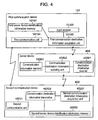
- Fig. 4 is a structural diagram of a communication system in this preferred embodiment.
- the communication system includes first communication device 101, second communication device 402, and server device 403. In this communication system, a call is made from first communication device 101 to second communication device 402.
- Second communication device 402 includes second communication unit 1020, second communication destination information acquisition unit 40201, second server device identification information memory 40202, and communication destination information transmitter 40203.
- Second communication destination information acquisition unit 40201 acquires communication destination information that is information for establishing communication with second communication device 402.
- Second communication destination information acquisition unit 40201 Any method is preferable for second communication destination information acquisition unit 40201 to obtain communication destination information.
- Second communication destination information acquisition unit 40201 receives, for example, communication destination information from an external device of a wireless communication base station.
- the way of realizing second communication destination information acquisition unit 40201 varies with the method of acquiring communication destination information.
- Second communication destination information acquisition unit 40201 is, for example, realized by a wireless communication device.
- Second server device identification information memory 40202 stores server device identification information that is information for accessing to server device 403. Any server device identification information is preferable, if the information is for accessing to server device 403.
- Server device identification information is, for example, the IP address of server device 403 or an electronic mail address for delivering the information to server device 403. Also, the IP address may be any address such as an IP address of IP Ver4 or an IP address of IP Ver6.
- Second server device identification information memory 40202 can be realized by non-volatile recording medium or volatile recording medium.
- Communication destination information transmitter 40203 transmits communication destination information acquired by second communication destination information acquisition unit 40201 to server device 403 identified by server device identification information.
- Communication destination information transmitter 40203 can be usually realized by a wireless communication device.
- second communication unit 10201 usually has a function of receiving communication destination information from a wireless communication base station.
- second communication device 402 it is preferable to realize second communication unit 10201, second communication destination information acquisition unit 40201, and communication destination information transmitter 40203 with physically one wireless communication device.
- first communication device 101 may be configured in the same structure as second communication device 402. Accordingly, first communication device 101 may have the same functions as those of second communication device 402.
- first communication destination acquisition unit 10103 and second communication destination acquisition unit 40202 acquire communication destination information that is information for communicating with the communication device itself, and also acquire communication destination information of the communication counterpart from server device 403.
- second communication device 402 may include an input receiver.
- Server device 403 includes communication information memory 10301, communication destination information receiver 40301, and communication destination updating unit 40302. That is, communication destination information receiver 40301 and communication destination information updating unit 40302 are added to the configuration of the preferred embodiment 1.
- Communication destination information receiver 40301 receives communication destination information from second communication device 402.
- Communication destination information receiver 40301 can be realized by a wireless or cable communication device.
- Communication destination information updating unit 40302 registers the communication destination information received by communication destination information receiver 40301 as updated communication destination information of communication information memory 10301.
- to register means, for example, overwriting the received communication destination with respect to communication destination information stored in communication information memory 10301.
- Communication destination information updating unit 40302 can be usually realized by software, but it may be realized by using hardware such as an exclusive circuit.
- second communication device 402 for transmitting communication destination information to server device 403 is described by using the flow chart of Fig. 5.
- Step S501 It is judged whether second communication destination information acquisition unit 40201 has acquired the communication destination information of second communication device 402 itself. In case it has acquired the communication destination information, it goes to step S502, and if it has not acquired the communication destination information, then step S501 is repeated.
- Step S502 Communication destination information transmitter 40203 takes out server device identification information from second server device identification information memory 40202.
- Step S503 Communication destination information transmitter 40203 transmits communication destination information obtained in step S501 to the server device identified by server device identification information fetched in step S502.
- the second communication device judges whether the communication destination information of the second communication device itself is changed, and only when changed, the second communication device may transmit the communication destination information to the server device.
- second communication device 402 is configured as described in the following.
- a change detector not shown which detects the change of communication destination information that is information for communicating with second communication device 402.
- Communication destination information transmitter 40203 transmits communication destination information to server device 403 when the change detector detects the change of communication destination information.
- communication destination information may be acquired periodically. Also, only when communication destination information is changed due to a movement of the second communication device, communication destination information may be acquired by transmitting communication destination information from a base station or the like to the second communication device.
- communication destination information transmitter 40203 usually transmits unique information of second communication device 402 together with communication destination information to server device 403.
- Server device 403 rewrites the communication information that corresponds, that is, matches with the unique information.
- server device 403 for receiving and registering communication destination information will be described by using the flow chart of Fig. 6.
- Step S601 It is judged whether communication destination information receiver 40301 has received communication destination information. In case it has received communication destination information, it goes to step S602, and if it has not received communication destination information, then step S601 is repeated.
- Step S602 Communication destination information updating unit 40302 retrieves the portion of registering the communication destination information received in step S601.
- the registering portion exists in communication information memory 10301.
- retrieving the registering portion means, for example, executing the following processing.
- Communication destination information receiver 40301 receives, for example, the communication destination information and the unique information of second communication device 402 in the form of a pair. Further, communication destination information updating unit 40302 obtains communication information including communication destination information, by using the received unique information as a key.
- Step S603 Communication destination information updating unit 40302 registers the communication destination information received in step S601 in the registering portion retrieved in step S602.
- the first communication device and the second communication device are mobile portable telephones.
- the server device stores communication information shown in Fig. 3. Also, assume that unique information of the second communication device is "010-2222-3333.” That is, the second communication device is an IP telephone using Internet.
- the second communication device moves, and the communication destination information of the second communication device changes according to the movement.
- the communication destination information of the second communication device changed in accordance with the movement of the second communication device is "1080::5:2A11:11DE:555C.”
- the second communication device receives, for example, an IP address "1080::5:2A11:11DE:555C" assigned to the second communication device from a wireless communication base station of the destination. Then, the second communication device transmits the received IP address "1080::5:2A11:11DE:555C" to the server device. In transmission, the second communication device also transmits its unique information "010-2222-3333" to the server device.
- the server device receives the IP address "1080::5:2A11:11DE:555C" and the unique information "010-2222-3333" from the second communication device. Subsequently, the server device changes communication destination information corresponding to the unique information "010-2222-3333" of the table (communication information management table) for the management of communication information of Fig. 3 into "1080::5:2A11:11DE:555C.” As a result, the communication information management table becomes as shown in Fig. 7.
- the second communication device may transmit communication destination information to the server device when the change of the communication destination information is detected by the change detector. Also, the second communication device may always transmit communication destination information to the server device when it acquires communication destination information.
- the server device may always register the communication destination information received from the second communication device. Also, the server device compares the communication destination information stored in the communication information memory with the communication destination information, and there is a difference between the two, to the server device may register the communication destination information received.
- the server device receives communication destination information from the second communication device which are moving, and the server device is always able to maintain the communication destination information of the place at which the second communication device moves. Accordingly, wherever the second communication device moves, the first communication device is able to properly establish communication with the second communication device.
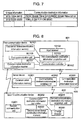
- Fig. 8 is a structural diagram of a communication system in this preferred embodiment.
- the communication system includes first communication device 801, second communication device 802, and server device 403. In this communication system, a call is made from first communication device 801 to second communication device 802.
- Server device 403 is configured in the same structure as in the preferred embodiment 2.
- First communication device 801 includes first server device identification information memory 10101, input receiver 10102, first communication destination information acquisition unit 10103, first communication unit 80103, communication destination information receiver 80101, and communication controller 80102.
- Communication destination information receiver 80101 receives communication destination information from second communication device 802 during the communication with second communication device 802.
- Communication destination information receiver 80101 is usually realized by a wireless communication device.
- Communication controller 80102 instructs first communication unit 10104 to change over the destination to the destination shown by the received communication destination information when communication destination information receiver 80101 receives new communication destination information.
- Communication controller 80102 can be usually realized by software, but it may be realized by hardware (an exclusive circuit).
- First communication unit 80103 establishes communication with second communication device 802. Also, when new communication destination information is received from communication controller 80102 during the communication, the communication is made by changing it over to the destination shown by the new communication destination information.
- First communication unit 80103 can be usually realized by wireless communication device.
- First communication unit 80103 includes software or the like for communicating by changing it over to the destination shown by the new communication destination information.
- Second communication device 802 includes second communication unit 10201, second communication destination information acquisition unit 40201, second server device identification information memory 40202, change detector 80201, and communication destination information transmitter 80202.
- Change detector 80201 detects that the change of the communication destination information of second communication device 802 itself. Any method for detecting the change may be employed. Change detector 80201 receives communication destination information from a base station for wireless communication, for example, only when the communication destination information of second communication device 802 itself is changed. Also, change detector 80201 receives communication destination information from a wireless communication base station for example periodically or at all times, and compares the last communication destination information being stored with the communication destination information received, and if both do not coincide with each other, it is judged that the communication destination information is changed.
- Change detector 80201 is usually realized by software, but it may be realized by hardware.
- second communication unit 10201 usually has a function of receiving communication destination information from a wireless communication base station.
- Communication destination information transmitter 80202 transmits communication destination information acquired by second communication destination information acquisition unit 40201 to first communication device 801 when the change of communication destination information is detected by change detector 80201 during communication with first communication device 801.
- communication destination information transmitter 80202 transmits the communication destination information acquired by second communication destination information acquisition unit 40201 to server device 403 as well, when change detector 80201 detects the change of communication destination information. Since second communication device 802 and first communication device 801 are communicating with each other, communication destination information transmitter 80202 is able to transmit the new communication destination information to first communication device 801.
- server device identification information of server device 403 is obtained from second server device identification information memory 40202.
- Communication destination information 80202 is usually realized by a wireless communication device.
- first communication device 801 is described by using the flow chart of Fig. 9.
- first communication device 801 obtains communication destination information of second communication device 802 from second communication device 802 during communication with second communication device 802. Thus, the communication is continued between first communication device 801 and second communication device 802.
- first communication device 801 for starting communication with second communication device 802 is preformed in the same manner as the operation described by using the flow chart of Fig. 2, and the description is omitted.
- Step S901 Communication destination information receiver 80101 judges whether it has received communication destination information from second communication device 802 during the communication with second communication device 802. In case it has received communication destination information, it goes to step S902, and if it has not received communication destination information, then step S901 is repeated.
- Step S902 Communication controller 80102 instructs first communication unit 10104 to change over the destination to the destination shown by the communication destination information received.
- Step S903 First communication unit 80103, during communication with second communication device 802, changes over the communication destination information of second communication device 802 to new communication destination information in order to continue the communication with second communication device 802.
- Such processing is usually executed according to the following procedure.
- First communication unit 80103 finishes calling to second communication device 802 shown by the previous communication destination information, and makes a call to second communication device 802 shown by the new communication destination information to resume the communication with second communication device 802. That is, first communication unit 80103 immediately resumes the communication after once finishing communication. Because the processing speed is very fast, the users of first communication device 801 and second communication device 802 will feel like that the communication is made continuously.
- second communication device 802 will be described by using the flow chart of Fig. 10.
- second communication device 802 transmits communication destination information to first communication device 801 during communication with first communication device 801. Thus, the communication is continued between first communication device 801 and second communication device 802.
- Second communication destination information acquisition unit 40201 acquires communication destination information of second communication device 802 itself. Any method is preferable for second communication destination information acquisition unit 40201 to obtain communication destination information. For example, second communication destination information acquisition unit 40201 periodically receives communication destination information from a wireless communication base station located in the neighborhood.
- Step S1002 Change detector 80201 compares the latest communication destination information with communication destination information received in step S1001, and judges whether the communication destination information of second communication device 802 is changed.
- step S1003 the process goes to step S1003, and if the communication destination information is not changed, then it returns to step S1001.
- second communication device 802 always stores the latest communication destination information (current communication destination information). That is, second communication device 802 records the new communication destination information as the current communication destination information when the communication destination information is changed.
- Step S1003 Communication destination information transmitter 80202 transmits the communication destination information acquired in step S1001 to first communication device 801. Second communication device 802 is able to transmit the communication destination information because second communication device 802 are communicating with first communication device 801.
- Step S1004 Communication destination information transmitter 80202 obtains server device identification information from second server device identification information memory 40202.
- Step S1005 Communication destination information transmitter 80202 transmits the communication destination information obtained in step S1001 to server device 403 identified by the server device identification information obtained in step S1004.
- change detector 80201 detects the change of communication destination information.
- communication destination information may be processed in the following way.
- second communication device 802 Only when the communication destination information of second communication device 802 changes, second communication device 802 obtains communication destination information from the outside. In that case, second communication device 802 may transmit communication destination information to first communication device 801 and server device 403 without making any judgment.
- second communication device 802 when first communication device 801 and second communication device 802 are communicating with each other, second communication device 802 transmits new communication destination information to server device 403. Also, after the termination of communication, second communication device 802 may transmit new communication destination information to server device 403.
- First communication device 801 and second communication device 802 have been described above.
- first communication device 801 and second communication device 802 may have the same configuration.
- first communication device 801 may further include a communication destination information transmitter equivalent to communication destination information transmitter 80202 and a change detector equivalent to change detector 80201.
- second communication device 802 may further include an input receiver equivalent to input receiver 10102, a communication destination information receiver equivalent to communication destination information receiver 80101, and a communication controller equivalent to communication controller 80102.
- the first communication device and the second communication device are mobile portable telephones.
- the server device stores communication information shown in Fig. 3.
- the unique information of the second communication device is "010-2222-3333.” That is, the second communication device operates as an IP telephone using Internet.
- the communication destination information of the second communication device changes in accordance with the movement of the second communication device.
- the communication destination information of the second communication device changed in accordance with the movement is "1080::5:2A11:11DE:555C.”
- the second communication device for example receives IP address "1080::5:2A11:11DE:555C" assigned to the second communication device from a wireless communication base station of the area to which the second communication device has moved. Subsequently, the second communication device transmits the received IP address "1080::5:2A11:11DE:555C" to the first communication device with which it is communicating. Also, the second communication device transmits the received IP address "1080::5:2A11:11DE:555C" to the server device as well.
- the first communication device receives a new IP address of the second communication device, and changes over the destination to the new IP address "1080::5:2A11:11DE:555C" to continue the communication.
- the server device changes the communication information management table to the one shown in Fig. 7 as described in the preferred embodiment 2.
- the amount of communication traffic between server device and Internet can be reduced, and it is possible to provide a communication system being free from problems such as congestion.
Landscapes
- Engineering & Computer Science (AREA)
- Computer Networks & Wireless Communication (AREA)
- Signal Processing (AREA)
- Telephonic Communication Services (AREA)
- Mobile Radio Communication Systems (AREA)
- Data Exchanges In Wide-Area Networks (AREA)
Applications Claiming Priority (3)
| Application Number | Priority Date | Filing Date | Title |
|---|---|---|---|
| JP2002126829 | 2002-04-26 | ||
| JP2002126829A JP2003318957A (ja) | 2002-04-26 | 2002-04-26 | 通信システムおよびサーバ装置 |
| PCT/JP2003/005242 WO2003092228A1 (fr) | 2002-04-26 | 2003-04-24 | Systeme de communication, dispositif de serveur utilise dans le systeme de communication, dispositif de communication, et programme d'execution du procede de communication dudit dispositif de communication |
Publications (1)
| Publication Number | Publication Date |
|---|---|
| EP1496651A1 true EP1496651A1 (de) | 2005-01-12 |
Family
ID=29267617
Family Applications (1)
| Application Number | Title | Priority Date | Filing Date |
|---|---|---|---|
| EP20030725656 Withdrawn EP1496651A1 (de) | 2002-04-26 | 2003-04-24 | Kommunikationssystem, in dem kommunikationssystem verwendete servervorrichtung, kommunikationsvorrichtung, sowie ein programm zur ausführung eines kommunikationsverfahrens der kommunikationsvorrichtung |
Country Status (6)
| Country | Link |
|---|---|
| US (1) | US20050144220A1 (de) |
| EP (1) | EP1496651A1 (de) |
| JP (1) | JP2003318957A (de) |
| CN (1) | CN1647469A (de) |
| AU (1) | AU2003231480A1 (de) |
| WO (1) | WO2003092228A1 (de) |
Families Citing this family (3)
| Publication number | Priority date | Publication date | Assignee | Title |
|---|---|---|---|---|
| JP4515358B2 (ja) * | 2005-08-30 | 2010-07-28 | 株式会社エヌ・ティ・ティ・ドコモ | 通信制御装置および通信制御方法 |
| WO2008017913A2 (en) * | 2006-08-07 | 2008-02-14 | Nokia Corporation | Connecting a first device and a second device |
| JP5115746B2 (ja) * | 2009-01-28 | 2013-01-09 | Necビッグローブ株式会社 | 通信システム、サーバ装置、情報処理方法およびプログラム |
Family Cites Families (7)
| Publication number | Priority date | Publication date | Assignee | Title |
|---|---|---|---|---|
| JP3559433B2 (ja) * | 1997-09-09 | 2004-09-02 | 株式会社東芝 | 通信システム |
| ATE324006T1 (de) * | 1999-01-08 | 2006-05-15 | Netnumber Com Inc | Verfahren und gerät zur korrelation eines einzigartigen identifizierers, wie z.b. eine pstn telefonnummer, an eine internetadresse zur kommunikation über das internet |
| JP2001127883A (ja) * | 1999-10-26 | 2001-05-11 | Ryoichi Komai | インターネット電話システム |
| JP2001144811A (ja) * | 1999-11-17 | 2001-05-25 | Sharp Corp | モバイルipにおける通信制御方式 |
| JP2002101122A (ja) * | 2000-09-21 | 2002-04-05 | Toshiba Corp | 通信システムおよび通信方法 |
| JP3856427B2 (ja) * | 2001-09-28 | 2006-12-13 | 有限会社デンタルサプライ | 端末間の接続方法 |
| US20030208602A1 (en) * | 2002-04-08 | 2003-11-06 | Cisco Technology, Inc. | System and method for pushing data in an internet protocol network environment |
-
2002
- 2002-04-26 JP JP2002126829A patent/JP2003318957A/ja active Pending
-
2003
- 2003-04-24 EP EP20030725656 patent/EP1496651A1/de not_active Withdrawn
- 2003-04-24 CN CNA038089130A patent/CN1647469A/zh active Pending
- 2003-04-24 WO PCT/JP2003/005242 patent/WO2003092228A1/ja active Application Filing
- 2003-04-24 US US10/512,176 patent/US20050144220A1/en not_active Abandoned
- 2003-04-24 AU AU2003231480A patent/AU2003231480A1/en not_active Abandoned
Non-Patent Citations (1)
| Title |
|---|
| See references of WO03092228A1 * |
Also Published As
| Publication number | Publication date |
|---|---|
| US20050144220A1 (en) | 2005-06-30 |
| JP2003318957A (ja) | 2003-11-07 |
| CN1647469A (zh) | 2005-07-27 |
| AU2003231480A1 (en) | 2003-11-10 |
| WO2003092228A1 (fr) | 2003-11-06 |
Similar Documents
| Publication | Publication Date | Title |
|---|---|---|
| KR100945972B1 (ko) | 코어 기반 노드를 사용하여 상태를 전송하기 위한 향상된 기술들 | |
| CA2495093A1 (en) | Providing routing information in a communication system | |
| EP1179950A2 (de) | System zur Kommunikationssteuerung mittels eines Telefonverzeichnises | |
| RU2419238C1 (ru) | Система и способ распределения общей информации о местоположении между устройствами связи | |
| EP1253796A2 (de) | Methode zur Auswahl eines Netwerkzugriffsmitteln aus verschiedenen Zugriffsmittels | |
| WO2001082532A1 (en) | A communication method and apparatus | |
| WO2008095097A1 (en) | System and method for sharing event-triggered, location-related information between communication devices | |
| US20050108574A1 (en) | Method and system for communication between a multi-modal device and a web application | |
| JP4672246B2 (ja) | 携帯端末、及び電話帳管理システム | |
| US20080234004A1 (en) | Accessing A Multimedia Service From A Mobile Terminal | |
| WO2006017758A1 (en) | Method and system for determining a destination in a mobile radio | |
| US7188167B2 (en) | Method and system for registering multiple communication devices of a user in a session initiation protocol (SIP) based communication system | |
| EP1496651A1 (de) | Kommunikationssystem, in dem kommunikationssystem verwendete servervorrichtung, kommunikationsvorrichtung, sowie ein programm zur ausführung eines kommunikationsverfahrens der kommunikationsvorrichtung | |
| US20040085970A1 (en) | System and method for accessing wireless internet | |
| CN106850556A (zh) | 服务访问方法、装置及设备 | |
| KR100639641B1 (ko) | 이동 통신 장치를 위한 수요-기반의 프로비저닝 | |
| JP2004140716A (ja) | プレゼンス情報対応通信端末 | |
| EP2214389B1 (de) | Nachrichtenrelais-system mit nachrichtenrelais-server | |
| JPH10233808A (ja) | ゲートウェイ選択方法及び装置 | |
| JP2022056190A (ja) | 車載ハンズフリー装置及び通信制御方法 | |
| CN112969199A (zh) | 一种数据采集方法和设备 | |
| EP1309154B1 (de) | System und Verfahren zur Auswahl elektronischer Dienste durch Infrarotkommunikation | |
| JP4784314B2 (ja) | 電話通信システム | |
| KR20010021123A (ko) | 인터넷 폰 통화 시스템 및 그 방법 | |
| EP1533975A2 (de) | Verfahren und System zur Kommunikation zwischen einem multimodalen Endgerät und einer Webanwendung |
Legal Events
| Date | Code | Title | Description |
|---|---|---|---|
| PUAI | Public reference made under article 153(3) epc to a published international application that has entered the european phase |
Free format text: ORIGINAL CODE: 0009012 |
|
| 17P | Request for examination filed |
Effective date: 20041025 |
|
| AK | Designated contracting states |
Kind code of ref document: A1 Designated state(s): AT BE BG CH CY CZ DE DK EE ES FI FR GB GR HU IE IT LI LU MC NL PT RO SE SI SK TR |
|
| AX | Request for extension of the european patent |
Extension state: AL LT LV MK |
|
| RAP1 | Party data changed (applicant data changed or rights of an application transferred) |
Owner name: PANASONIC CORPORATION |
|
| STAA | Information on the status of an ep patent application or granted ep patent |
Free format text: STATUS: THE APPLICATION IS DEEMED TO BE WITHDRAWN |
|
| 18D | Application deemed to be withdrawn |
Effective date: 20091102 |