EP1496306B1 - Vorrichtung und Verfahren zur Nachahmung von Flammen - Google Patents
Vorrichtung und Verfahren zur Nachahmung von Flammen Download PDFInfo
- Publication number
- EP1496306B1 EP1496306B1 EP04015021A EP04015021A EP1496306B1 EP 1496306 B1 EP1496306 B1 EP 1496306B1 EP 04015021 A EP04015021 A EP 04015021A EP 04015021 A EP04015021 A EP 04015021A EP 1496306 B1 EP1496306 B1 EP 1496306B1
- Authority
- EP
- European Patent Office
- Prior art keywords
- flame
- computation
- procedure
- computing
- lattice
- Prior art date
- Legal status (The legal status is an assumption and is not a legal conclusion. Google has not performed a legal analysis and makes no representation as to the accuracy of the status listed.)
- Expired - Lifetime
Links
Images


Classifications
-
- F—MECHANICAL ENGINEERING; LIGHTING; HEATING; WEAPONS; BLASTING
- F21—LIGHTING
- F21S—NON-PORTABLE LIGHTING DEVICES; SYSTEMS THEREOF; VEHICLE LIGHTING DEVICES SPECIALLY ADAPTED FOR VEHICLE EXTERIORS
- F21S10/00—Lighting devices or systems producing a varying lighting effect
- F21S10/04—Lighting devices or systems producing a varying lighting effect simulating flames
-
- F—MECHANICAL ENGINEERING; LIGHTING; HEATING; WEAPONS; BLASTING
- F21—LIGHTING
- F21S—NON-PORTABLE LIGHTING DEVICES; SYSTEMS THEREOF; VEHICLE LIGHTING DEVICES SPECIALLY ADAPTED FOR VEHICLE EXTERIORS
- F21S9/00—Lighting devices with a built-in power supply; Systems employing lighting devices with a built-in power supply
- F21S9/02—Lighting devices with a built-in power supply; Systems employing lighting devices with a built-in power supply the power supply being a battery or accumulator
-
- H—ELECTRICITY
- H05—ELECTRIC TECHNIQUES NOT OTHERWISE PROVIDED FOR
- H05B—ELECTRIC HEATING; ELECTRIC LIGHT SOURCES NOT OTHERWISE PROVIDED FOR; CIRCUIT ARRANGEMENTS FOR ELECTRIC LIGHT SOURCES, IN GENERAL
- H05B39/00—Circuit arrangements or apparatus for operating incandescent light sources
- H05B39/09—Circuit arrangements or apparatus for operating incandescent light sources in which the lamp is fed by pulses
-
- H—ELECTRICITY
- H05—ELECTRIC TECHNIQUES NOT OTHERWISE PROVIDED FOR
- H05B—ELECTRIC HEATING; ELECTRIC LIGHT SOURCES NOT OTHERWISE PROVIDED FOR; CIRCUIT ARRANGEMENTS FOR ELECTRIC LIGHT SOURCES, IN GENERAL
- H05B47/00—Circuit arrangements for operating light sources in general, i.e. where the type of light source is not relevant
- H05B47/10—Controlling the light source
- H05B47/155—Coordinated control of two or more light sources
-
- F—MECHANICAL ENGINEERING; LIGHTING; HEATING; WEAPONS; BLASTING
- F21—LIGHTING
- F21W—INDEXING SCHEME ASSOCIATED WITH SUBCLASSES F21K, F21L, F21S and F21V, RELATING TO USES OR APPLICATIONS OF LIGHTING DEVICES OR SYSTEMS
- F21W2121/00—Use or application of lighting devices or systems for decorative purposes, not provided for in codes F21W2102/00 – F21W2107/00
-
- Y—GENERAL TAGGING OF NEW TECHNOLOGICAL DEVELOPMENTS; GENERAL TAGGING OF CROSS-SECTIONAL TECHNOLOGIES SPANNING OVER SEVERAL SECTIONS OF THE IPC; TECHNICAL SUBJECTS COVERED BY FORMER USPC CROSS-REFERENCE ART COLLECTIONS [XRACs] AND DIGESTS
- Y10—TECHNICAL SUBJECTS COVERED BY FORMER USPC
- Y10S—TECHNICAL SUBJECTS COVERED BY FORMER USPC CROSS-REFERENCE ART COLLECTIONS [XRACs] AND DIGESTS
- Y10S362/00—Illumination
- Y10S362/80—Light emitting diode
-
- Y—GENERAL TAGGING OF NEW TECHNOLOGICAL DEVELOPMENTS; GENERAL TAGGING OF CROSS-SECTIONAL TECHNOLOGIES SPANNING OVER SEVERAL SECTIONS OF THE IPC; TECHNICAL SUBJECTS COVERED BY FORMER USPC CROSS-REFERENCE ART COLLECTIONS [XRACs] AND DIGESTS
- Y10—TECHNICAL SUBJECTS COVERED BY FORMER USPC
- Y10S—TECHNICAL SUBJECTS COVERED BY FORMER USPC CROSS-REFERENCE ART COLLECTIONS [XRACs] AND DIGESTS
- Y10S362/00—Illumination
- Y10S362/806—Ornamental or decorative
- Y10S362/81—Imitation candle
Definitions
- the present invention relates to an imitation flame generating apparatus, and more particularly to an imitation flame generating apparatus in which the change of field variables relating to an appropriately cause graining flame is computed using a coupled map lattice associated with the space in which the flame is represented.
- an illumination light source by varying the current supplied to the light source in order to electrically simulate the flickering of a candle light, for example, is generally known.
- One of the most general methods is employed in an atmosphere-producing lighting apparatus in which light sources, such as light-emitting diodes, are supplied with a current that varies at certain periods over time (see, for example, Patent Document 1).
- An electric candle in which a lighting member is blinked using a random signal generating device, so that an irregular, rather than periodic, light can be obtained (see, for example, Patent Document 2) is also known.
- An illuminating device is also known in which, in order to obtain a more comfortable lighting condition by taking advantage of the 1/f fluctuation properties, an output waveform is generated using a 1/f filter, and a varying signal obtained by a wind velocity sensor is given to the output waveform (see, for example, Patent Document 3).
- a religious device employs a flickering light member.
- an actual flame is subjected to chaotic analysis based on chaos theory on a personal computer in advance, and data with values relatively close to those of the flame is created and stored in a memory device. Then, LEDs are turned on using the thus stored chaotic data in a repeated manner (see, for example, Patent Document 4).
- an illuminating device comprises a plurality of light sources arranged in a manner resembling a candle flame. The amount of light emitted by each light source is varied based on a plurality of pieces of data stored in a memory device in advance, such that the flickering of the flame can be simulated (see, for example, Patent Document 5)
- US 5 924 784 shows an imitation flame generating apparatus according to the preamble of claim 1.
- the light produced by the lighting apparatus that emits light with periodicity is monotonous. Randomly emitted illumination is quite dissimilar from the actual, flickering light produced by a lit candle.
- the lighting apparatus that emits light with a 1/f fluctuation merely operates the light source at 1/f periods, which is a characteristic obtained by arranging the power spectrum using a temporal frequency component. Thus, in this apparatus, it cannot be said that actual combustion is accurately represented. Further, in the apparatus comprising a plurality of light sources that utilize the 1/f fluctuation, since the light sources are turned on with the same timing without mutually influencing one another, and since the flame is expressed in a virtual space, the peculiar warmth of a flame in a real space cannot be produced in the virtual space even if the light sources have different amounts of light.
- a light source is operated in accordance with data based on physical property changes in natural phenomena (such as the flickering of flame or sound).
- the captured data is used in a repetitive manner, the data is periodic in the long run such that it cannot be said that the flickering of a flame, which is irregular, is accurately reproduced.
- the analysis is based on a temporal topological space, which means that the light source is turned on using time as a variable. In this case, only temporal fluctuation is expressed and a flame in a real space is not expressed.
- a plurality of light sources are turned on, although they vary in time, they cannot be turned on such that one light source influences another.
- a large data storage volume must be provided, which would lead to an increase in the size of the apparatus and in manufacturing cost.
- the invention provides an imitation flame generating apparatus comprising a light source and a control device for controlling the output of an electric current to the light source.
- the control device comprises a computing means for computing a spatiotemporal pattern of a flame using a coupled map lattice, and an output means for outputting the electric current in accordance with the computed spatiotemporal pattern of the flame.
- the coupled map lattice may comprise a field variable relating to a flame
- said computation means comprises a procedure for computing said field variable relating to the flame using a control parameter.
- the field variable relating to the flame may comprise a substance amount, an internal energy amount, and a momentum
- the computing procedure may comprise a procedure for computing combustion, a procedure for computing expansion, and a procedure for computing diffusion.
- the computing means may compute the spatiotemporal pattern of the flame based on the combustion computation procedure, the expansion computation procedure, and the diffusion computation procedure.
- the computation means may be capable of inputting and changing the field variable relating to the flame and/or the control parameter.
- the invention also provides an imitation flame generating method for generating an imitation flame by controlling an electric current supplied to a light source.
- the method comprises computing a spatiotemporal pattern of a flame for generating an imitation flame using a coupled map lattice, and supplying the output current in accordance with the thus computed spatiotemporal pattern of a flame to turn on said light source.
- the coupled map lattice may comprise a field variable relating to an appropriately cause graining flame
- said computation means comprises a procedure for computing the field variable relating to the flame using a control parameter.
- the field variable relating to the flame may comprise a substance amount, an internal energy amount, and a momentum
- the computing procedure may comprise a procedure for computing combustion, a procedure for computing expansion, and a procedure for computing diffusion.
- the computation may involve the computation of the spatiotemporal pattern of the flame using the combustion computation procedure, the expansion computation procedure, and the diffusion computation procedure.
- the field variable relating to the flame and/or the control parameter may be inputted and changed during the computation.
- the imitation flame generating apparatus of the invention it is possible to reproduce a space that extremely resembles the state of an actual flame, namely, imitate the spatiotemporal pattern of the flame, without depending on temporal periods.
- the adjacent light sources can be caused to emit light such that they affect each other, such that the individual light sources can emit light in a natural manner and, when the light sources are viewed as a whole, they can emit warm light resembling an actual flame.
- the light sources can emit light that resembles the actual flame.
- the physical values as initial values indicating the conditions of the field variables relating to a flame can be entered during the computation.
- Various types of flame can be represented in accordance with the surrounding environments in a real-time manner.
- the light sources can be controlled in a real-time manner such that an effect similar to the flame flickering due to a breeze or other external influences can be provided.
- the invention allows a flame to be reproduced without burning matter, it can provide an effective lighting source that is safe and environmentally friendly.
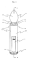
- FIG. 1 shows a perspective view of the imitation flame generating apparatus 1 of the present embodiment
- Fig. 2 shows a cross section taken along line II - II of Fig. 1 .
- the imitation flame generating apparatus 1 which is an apparatus for reproducing a lit candle, includes a holding case 20 which is hollow and cylindrical in shape, and an imitation flame portion 30 which is similar in shape to an actual flame and has a cream-colored internal bore.
- the holding case 20 is bonded to the imitation flame portion 30 with an adhesive or the like.
- a circular, light-source mount plate 23 is bonded to one end of the holding case 20 with an adhesive or the like.
- five light sources 10 employing LEDs, for example, are mounted, of which one is disposed at center and the remaining four are disposed around the central light source at equal intervals.
- a light switch 33 for turning on the light sources 10 is mounted in a rotatable manner.
- the holding case 20 further includes a through hole 22 providing communication between the inside and the outside, and a sliding cover 21 allowing for the insertion and extraction of a battery 31 in a battery box 32 provided inside the casing.
- a control device 40 In addition to the battery 31, there are further provided in the holding case 20 a control device 40, a voice detection sensor 36 disposed facing toward the through hole 22, and an input terminal 44 for allowing for the input of data from an external input device (not shown), via a wire 46, to the control device 40.
- a terminal 34 comes into electrical contact with a wire 35 that is fixed to the holding case 20, thereby allowing an electric power to be supplied from the battery 31 to the control device 40.
- the voice detection sensor 36 and each light source 10 are electrically connected to the control device 40 so that they can send and receive signals between one another.
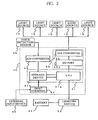
- Fig. 3 shows a control block diagram of the internal configuration of the imitation flame generating apparatus 1 of the present embodiment, which includes the light source 10, battery 31, light switch 33, control device 40 comprising a computing means 41 and an output means 42, and the voice detection sensor 36.
- the control device 40 Based on signals inputted from the voice detection sensor 36 and the external input device 45, which is located outside the imitation flame generating apparatus 1, the control device 40 performs computations to simulate the flame and controls the output of an electric current to the light sources 10 that are turned on.
- the external input device 45 which is provided outside the imitation flame generating apparatus 1 in the present embodiment, may be provided inside the imitation flame generating apparatus 1.
- the computation means 41 includes a CPU 41a and a memory device 41b.
- the output means 42 includes an I/O port 42a and a D/A converter 42b.
- the memory device 41b there are stored procedures for computing the field variables relating to the flame, using control parameters, in order to simulate the flame.
- the memory device 41b there are stored a combustion computation procedure, an expansion computation procedure, and a diffusion computation procedure.
- the CPU 41 a reads the control parameters indicating the state of the flame and the field variables relating to the flame (which will be described later), which are inputted to the memory device 41b from the external input device 45 via the input terminal 44. In accordance with these procedures, the CPU 41a repetitively performs computations concerning the change of the field variables relating to a flame.
- the external input device is capable of freely changing the control parameters and the field variables relating to the flame during the computation in accordance with the particular type of flame to be simulated.
- CPU 41 a can perform computations based on such a change and change the lighting condition of each light source 10 in a real-time manner.
- the voice detection sensor 36 is a sensor for detecting the external environment, and it is adapted to detect sound in a certain high frequency region such that it can detect the speed of wind around the imitation flame generating apparatus 1 based on the sound of wind.
- CPU 41 a reads the obtained measurement data from the memory device 41 b with a suitable timing during the repetitive computations and then incorporates them into the computations as the field variables (velocity field in the present case) relating to the flame.
- the D/A converter 42b in the control device 40 processes from degital data via the I/O port 42a to analog data, and then the control divice40 supplies an output current to each of the light sources 10 in order to turn them on, via the I/O port 42a.
- the output means 42 may include an operational amplifier for amplifying the signal. Because the output current is determined on the basis of a table of the relationships between current values and light amounts that have been measured in advance, the light sources can emit an amount of light that is close to the amount of light of a candle.
- Fig. 4 shows the software configuration of the computation means 40 in the imitation flame generating apparatus 1 in the present embodiment.
- the computation means 40 consists of a combustion computation means 401, a thermal expansion computation means 402, and a diffusion computation means 403. Computations are performed as these means are sequentially operated.
- Field variables 45a relating to the flame and control parameters 45b, which determine the spatiotemporal pattern of the flame, are suitably inputted from the external input device 45 to the individual computations means 401 to 403 constituting the computation means 41.
- wind velocity data 36a which constitutes data about field variables (velocity field) relating to the flame that are detected by the voice detection sensor 36, is inputted to the computation means.
- the computation means then outputs temperature data 10a, which constitutes an output signal to each light source 10.
- temperature data 10a which constitutes an output signal to each light source 10.
- the wind data is inputted to the thermal-expansion computation means 402 and the temperature data is outputted from the diffusion computation means 403, this is only an example, and other circuits may be employed for data input and output.
- the combustion computation means 401 computes the process representing the combustion of matter. Specifically, it computes the process in which, in the presence of sufficient energy to chemically react with the fuel present in each lattice (lattice to which field variables relating to a flame are given), which will be described later, and the oxygen in the air, carbon dioxide and vapor are produced, generating energy.
- lattice lattice to which field variables relating to a flame are given
- the oxygen in the air, carbon dioxide and vapor are produced, generating energy.
- an increase or decrease in the number of molecules is computed based on the chemical reaction involving the fuel, and the energy generated by this chemical reaction is computed.
- the expansion computation means 402 computes the process representing the distribution of matter present in regions with different energy levels. Specifically, it computes the process in which, as a thermal expansion velocity (velocity which contributes to expansion) is created in the field variables relating to the flame by the energy generated in each lattice due to combustion, for example, some of the field variables relating to the flame in each lattice move to adjacent, surrounding lattices.
- a thermal expansion velocity velocity which contributes to expansion
- the thermal expansion velocity is assumed to be created from a higher energy towards a lower energy (in an one direction), and the computation that takes the positional energy due to gravity into account.
- the diffusion computation means 403 performs computations representing the process in which, in a space with molecular density differences, the molecules diffuse in an attempt to achieve homogeneity. Namely, the process represents the phenomena whereby, as irregularities are created in the density of the molecules distributed in the individual lattices due to the post-combustion expansion, the adjacent molecules with density are diffused uniformly.
- the expansion computation means reads the wind velocity data 36a, which is external data, and then computes the movement of molecules and/or their energy change in a particular space due to the influence of wind.
- control parameters 45b By inputting appropriate control parameters 45b, a variety of types of flame, such as the flame of a candle or an alcohol lamp (where methanol is burned), can be reproduced.
- various flame patterns can be reproduced.
- the control parameters 45b can be changed during computation, and by so doing, the output condition of the light sources can be dynamically changed on a real-time basis.
- external changes can be incorporated on a real-time basis.
- Fig. 5 shows a coupled map lattice that is computed by the control device 40 of the imitation flame generating apparatus 1 according to the present embodiment.
- the coupled map lattice consists of field variables relating to a flame, and procedures for computing the field variables relating to the flame. Specifically, in order to compute the change of the field variables relating to the flame, divided spaces obtained by appropriately dividing a real space in which a flame is present are provided with, as the field quantities relating to the flame, appropriately cause graining physical quantities, such as molecules, energy, or momentum (velocity), that exist in the divided spaces. Then, computations are performed that take into consideration the interaction between the field variables relating to the flame and the adjacent field variables relating to the flame with the elapse of time.
- the dashed line in Fig. 5 indicates, in a two-dimensional real space, the shape of the flame of an actual candle that is being burned.
- a space representing the burning flame is divided into 16 elements useing a mesh of 4 x 4 rows and columns, and each element is allocated with a lattice.
- These lattices are defined as 16 field variables relating to the flame whereby the molecules in the space are cause graining.
- the lattices are represented in the mesh as the field variables relating to a flame, and in order to represent the states within the mesh, the field variables relating to the flame are allocated in the lattices.
- the shape of the flame is represented in a two-dimensional real space, the number of dimensions is not particularly limited and may be three, for example.
- the number of the elements in the mesh is not particularly limited either.
- a lattice at row i and column j is designated lattice ij.
- the field variables relating to the flame consist of the substance amount of oxygen molecules, the substance amount of fuel molecules, the substance amount of carbon dioxide molecules, the substance amount of vapor molecules, the substance amount of nitrogen molecules, the internal energy, the i-direction velocity, and the j-direction velocity. These field variables relating to the flame are designated as x 1, ij , x 2, ij , x 3, ij , x 4, ij , x 5, ij , e ij , v 1, ij , and v 2, ij , respectively.
- field variables relating to the flame temperature changes in each lattice are computed on a real-time basis, and the light sources are turned on in accordance with the thus computed temperatures h ij .
- the field variables relating to the flame consist of the substance amounts of oxygen, fuel, carbon dioxide, vapor, and nitrogen, other substance amounts may be given in accordance with the assumed combustion environment.
- variables such as a total substance amount n ij , mass m ij , temperature h ij , and momentum p ij can be derived.
- the total substance amount n ij that exists in the lattice ij is the value of the sum of the molecular substance amount of each molecule.
- the mass m ij that exists in the lattice ij has a value corresponding to the sum total of the products of the aforementioned five molecular substance amounts and each molecular amount.
- the temperature h ij in the lattice ij which constitutes the output data in the present example, is the value obtained by dividing the internal energy e ij by the total substance amount n ij .
- the momentum p ij in the lattice ij is the value of the product of the mass m ij and the velocities v 1 , ij , v 2 , ij .
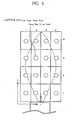
- Fig. 6 shows the lattices of Fig. 5 divided into five groups.
- Fig. 6(b) shows the arrangement of five light sources corresponding to the five groups of Fig. 6(a) .
- the temperature h ij in the lattice ij is repeatedly computed using the change of the field variables relating to the cause graining flame, which will be described later.
- the 16 lattices are divided into 5 groups, namely lattice groups 51 to 54 with three lattices each and a lattice group 55 with four lattices.
- the temperatures h ij possessed by each lattice in the groups are averaged, and proportional output currents are supplied to the light sources 11 to 15 (the aforementioned five light sources 10) in accordance with the averaged data.
- the above-described method of dividing into groups and the averaging of the individual temperatures are only examples, and any other methods may be employed as long as they are capable of associating the groups with the light sources.
- the candle flame is represented by a temporal as well as spatial pattern, resulting in the reproduction of a very realistic flame.
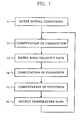
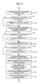
- Fig. 7 shows a control flowchart of the computation performed by the CPU 41 a in the imitation flame generating apparatus 1 according to the present embodiment.
- This computation corresponds to the computation performed by each of the computation means 401 to 403 shown in Fig. 4 , and it involves the aforementioned field variables (physical quantities) relating to the flame.
- the field variables relating to the flame are updated if and when necessary.
- the field variables relating to the flame that are not used in a relevant step are carried over to the subsequent step.
- Steps 71 to 76 will be briefly described.
- step 71 the field variables 45a relating to the flame and the control parameters 45b shown in Fig. 4 are entered into the CPU 41a, thus giving the initial conditions for the computations performed in the following steps.
- step 72 the process of combustion of oxygen and fuel, with the resulting increases in vapor and carbon dioxide and the generation of heat and temperature changes, is computed for each lattice, and then the field variables are updated.
- step 73 the wind velocity data 41 c obtained via the measurement signal from the voice detection sensor 36 is entered, and the increase in the velocity field (field variable) that is entered as disturbance is added to the subsequent computation of expansion.
- step 74 based on the expansion velocity produced by a change in internal energy due to the increase in step 72, a change in the field variables in each lattice is computed.
- step 75 diffusion of each substance from dense to coarse is computed.
- step 76 the temperature h ij is outputted with an appropriate timing and then converted into an output current value with which the light sources are turned on. This series of computations from step 72 through step 76 is repeated, so that the temperature h ij that is computed changes, and in response to this change, the output current also changes, which makes it possible to turn on the light sources in a manner resembling an actual flame.
- the processing rate in each step depends on the performance of the CPU, the process in each step generally takes from 1 to 100 ms.
- step 72 The details of the computation of combustion in step 72 shown in Fig. 7 will be described.
- the number of instances of combustion is calculated using chemical equations of combustion, and the field variables are updated according to the thus determined number of instances of combustion.
- Combustion is a chemical reaction in which hydrocarbon fuel molecules chemically bind to oxygen molecules, thereby producing carbon dioxide molecules and vapor molecules as well as generating heat and light.
- C S H 2S+2 is defined by the following chemical equation: ⁇ 1 C S H 2S+2 + ⁇ 2 O 2 ⁇ 3 CO 2 + ⁇ 4 H 2 O (1)
- the combustion of eicosane C 20 H 42 which indicates wax, is expressed by the following chemical equation: 2C 20 H 42 +61O 2 ⁇ 40CO 2 +42H 2 O (2)
- Equation 1 In a combustion according to Equation 1 (or 2), ⁇ 1 moles (2 moles) of fuel molecules and ⁇ 2 moles (61 moles) of oxygen molecules are consumed and instead ⁇ 3 moles (40 moles) of carbon dioxide molecules and ⁇ 4 moles (42 moles) of vapor molecules are produced.
- This reaction process proceeds in a chain-reactive manner from the moment when the temperature of the lattice ij exceeds a certain critical temperature. The process is maintained until either the fuel molecule substance amount x 1 , ij or the oxygen molecule substance amount x 2 , ij that exist in the lattice ij is completely consumed.
- the number of such reactions that take place (number of instances of combustion r ij ) is computed on the basis of the fuel molecule amount x 1, ij and the oxygen molecule substance amount x 2, ij that are given.
- x 1, ij / ⁇ 1 is determined, while using the oxygen molecule substance amount x 2, ij and the coefficient ⁇ 2 of the chemical equation, x 2, ij / ⁇ 2 is determined.
- the number of instances of combustion r ij is calculated by multiplying the smaller of the above two values (the total number of instances of complete combustion) by a probability of the chemical reaction taking place.
- the probability of chemical reaction is determined in accordance with a constitutive equation expressed by a function of the temperature t ij of the lattice ij in which the characteristic parameter of chain-reaction and the aforementioned critical temperature are taken into consideration.
- the field variables relating to the flame are updated. Specifically, the substance amount consumed, the substance amount produced, and the produced energy are determined based on the number of instances of combustion r ij , and the field variables (substance amounts) in each lattice, namely the fuel molecule substance amount x 1, ij, oxygen molecule substance amount x 2, ij, the carbon dioxide substance amount x 3, ij, the vapor substance amount x 4, ij, and the internal energy e ij , are adjusted to update the field variables relating to the flame.
- the nitrogen molecule substance amount x 5, ij, the velocity v 1, ij in the i-direction, and the velocity v 2, ij in the j-direction do not change in this computation of combustion.
- step 74 for computing expansion on the premise that the flame is a compressive fluid with the property to expand (or shrink), the following computation is performed. Namely, the substance amounts in the lattice ij are divided into four equal parts, and then computations are performed such that the thus equally divided four substance amounts and their associated internal energy e ij and momentum p ij are distributed (advected) into the lattice ij and the eight neighboring lattices (i+1j, i+1j+1, ij+1, i-1j+1, i-1j, i-1j-1, ij-1, i+1j-1; Moore-neighborhood) according to the momentum conservation law.
- distribution weights are calculated using the previously determined expansion velocity u d, ij and the field variables relating to the flame are updated. The details of these procedures will be described later with reference to Figs. 8 to 10 , and the control flow of relevant computations will also be described later by referring to Fig. 11 .
- FIG. 8 shows how the substance amounts in the lattice ij are divided and how they are distributed by the expansion momentum q d, ij .
- Fig. 9 shows the method of calculating the expansion velocity in a region with the positive i and positive j directions of the lattice ij.
- i-component of the expansion momentum q 1, ij which is generated from the lattice ij toward the lattice i+1j in dependence upon each internal enrgy, can be described as k(e ij - e i+1j ) (>0), which is the energy difference times constant k.
- the expansion momentum is calculated for the region with the negative i and positive j directions, the region with the positive i and negative j directions, and the region with the negative i and negative j directions.
- the potential energy (work by the gravity) must be taken into consideration because each molecule has a mass. Namely, when the lattice ij is compared with the lattice ij+1, in addition to the internal energy difference, the potential energy must be considered because the lattice ij+1 is located vertically above.
- the previously indicated calculation formula for the horizontal expansion momentum can be corrected by the potential energy ⁇ e according to the energy conservation law and therefore expressed as k(e ij - e ij+1 + ⁇ e p ).
- the expansion momentum is calculated in the same manner for the region with the negative i and positive j directions, the region with the positive i and negative j directions, and the region with the negative i and j directions, with reference to the lattice ij.
- the expansion velocity u 1, ij for the molecules in the lattice to be distributed to the neighboring lattices is calculated. Specifically, based on the expansion velocity u 1, ij and the inherent velocity of the lattice, and using the momentum conservation law, the expansion velocity u 11, ij in the i-direction and the expansion velocity u 12, ij in the j-direction of the expansion velocity u 1, ij are calculated.
- the thus calculated i-direction expansion velocity u 11, ij and the j-direction expansion velocity u 12, ij assume values that are within the range 0 ⁇
- Fig. 10 shows how the divided field variables relating to the flame are distributed to the surrounding lattices according to the i-direction expansion velocity u 11, ij and j-direction expansion velocity u 12, ij that have been calculated with reference to Fig. 9 .
- the field variables relating to the flame must be appropriately distributed to the original lattice ij and the Moore-neighborhood lattices in dependence on the magnitude of the expansion velocities except in the case where the magnitudes of the velocity vectors
- the distribution of the substances in the lattices is computed based on the areas of regions 101 to 104 shown in Fig. 10 .
- the area of region 101 is A
- that of region 102 is B
- that of region 103 is C
- that of region 104 is D
- C times the substance amount of the lattice ij (a quarter of the previously indicated substance amount) is distributed to the lattice ij
- D times the substance amount of the lattice ij is distributed to the lattice ij+1
- A times the substance amount of the lattice ij is distributed to the lattice i+1j+1
- B times the substance amount of the lattice ij is distributed to the lattice i+1j.
- This distribution method is referred to as a lever-rule distribution method, which is generally well known.
- Fig. 11 shows a control flowchart of the computation of expansion based on the expansion computation technique shown in Figs. 8 to 10 .
- step 111 the field variables relating to the flame for each lattice are divided. In the present example, all of the field variables relating to the flame for the lattice ij are divided into four parts, as described above.
- step 112 it is determined whether the objects of calculation lie vertically. If they are vertically laid, the routine proceeds to step 113, where corrections are made for the potential energy (work done by the gravity) according to the energy conservation law, as mentioned above. This is followed by step 114. If the objects of calculation do not lie vertically (when they lie horizontally), the routine proceeds to step 114 without performing the corrections.
- step 114 as shown in Fig. 9 , the expansion momentum is calculated based on the difference in internal energy between the lattices, and then the routine proceeds to step 115.
- step 118 it is determined whether the magnitudes of the expansion velocities
- 1 before proceeding to step 120. If the condition is not satisfied, the routine proceeds to step 120.
- step 120 the weights with which the field variables relating to the flame for the lattice ij are to be distributed to the neighboring lattices are calculated using the expansion velocities u d1, ij and u d2, ij , according to the lever-rule distribution method, as shown in Fig. 10 .
- step 121 based on the weights calculated in step 120, the weights to be distributed to the lattice ij from the neighboring lattices are extracted.
- step 122 using the thus extracted weights, the individual substance amounts distributed to each lattice are summed and updated.
- step 123 the internal energy is summed and updated by incorporating the work by the gravity in accordance with the energy conservation law.
- step 124 the momenta distributed in each lattice are also summed and updated, in accordance with the momentum conservation law.
- This diffusion is different from the action of the expansion (or shrinking) previously indicated and is considered in terms of a phenomenon that takes place on the level of the molecular motion of each substance.
- This phenomenon represents the diffusion of molecules in an attempt to achieve homogeneity in a space where molecular density differences are present. Specifically, because there are irregularities in the density of the molecules distributed in each lattice due to the post-combustion expansion, computations are performed to capture the phenomenon in which the density irregularities of the adjacent molecules become uniformly diffused.
- the computation of diffusion is performed by distributing certain amounts of the field variables relating to the flame in ij and their associated internal energy e ij and momentum p ij from the lattice ij to the Neumann-neighborhood lattices, regardless of their internal energy differences.
- Fig. 12 shows a control flowchart of step 75 for the computation of diffusion shown in Fig. 7 .
- step 131 the average substance amount for the lattices surrounding the lattice of concern is calculated.
- step 132 a deviation between the lattice of concern and the average substance amount is determined. This is for the purpose of determining a molecular density ratio of the lattice of concern to the surrounding lattices. The greater the deviation, the diffusion is more likely to occur.
- step 134 a deviation from an average value having as variables the temperatures that are distributed along with the substance amounts is calculated in the same method employed in the previous steps 131 and 133. By adding the work performed by gravity, the deviation value is updated in accordance with the energy conservation law. Then in step 135, a deviation from an average value having as variables the velocities that are distributed along with the substance amounts is calculated in accordance with the momentum conservation law, using the same method as in step 135.
- the values of the deviation namely the i-direction velocity v 1, ij and the j-direction velocity v 2, ij , are updated.
- the computations are based on a dynamic thermal-hydraulic phenomenon, the light sources can be turned on in a manner that more closely approximates the real flame. Moreover, because the computations are performed continuously, changes in external environments can be incorporated. It is also possible to modify the conditions of the flame in accordance with the user's preferences in a real-time manner.
- various other sensors such as airflow sensors and temperature sensors, may be employed individually or in combination as long as they are capable of measuring the condition of outside air surrounding the imitation flame generating apparatus.
Landscapes
- Engineering & Computer Science (AREA)
- General Engineering & Computer Science (AREA)
- Circuit Arrangement For Electric Light Sources In General (AREA)
- Non-Portable Lighting Devices Or Systems Thereof (AREA)
- Photometry And Measurement Of Optical Pulse Characteristics (AREA)
Claims (10)
- Vorrichtung zur Nachahmung einer Flamme (1) umfassend- eine Lichtquelle und- eine Steuervorrichtung (40) zur Steuerung der Ausgabe eines elektrischen Stroms an die Lichtquelle,
wobei die Steuervorrichtung (40) umfasst- Berechnungsmittel (41) zur Berechnung eines räumlich-zeitlichen Musters einer Flamme und- Ausgabemittel (42) zur Ausgabe des elektrischen Stroms auf der Grundlage des so berechneten räumlich-zeitlichen Musters einer Flamme,dadurch gekennzeichnet, dass
das Berechnungsmittel ein gekoppeltes Abbildungs-Gitter (coupled map lattice) verwendet. - Vorrichtung zur Nachahmung einer Flamme nach Anspruch 1, wobei das gekoppelte Abbildungs-Gitter eine einer Flamme zugeordnete Feldvariable umfasst, und das Berechnungsmittel ein Verfahren zur Berechnung der der Flamme zugeordneten Feldvariablen unter Verwendung eines Steuerungsparameters umfasst.
- Vorrichtung zur Nachahmung einer Flamme nach Anspruch 2, wobei die der Flamme zugeordnete Feldvariable eine Substanzmenge, eine innere Energiemenge und einen Impuls umfasst, und das Berechnungsverfahren ein Verfahren zur Berechnung der Verbrennung, ein Verfahren zur Berechnung der Ausdehnung und ein Verfahren zur Berechnung der Diffusion umfasst.
- Vorrichtung zur Nachahmung einer Flamme nach Anspruch 3, wobei das Berechnungsmittel das räumlich-zeitliche Muster der Flamme auf der Grundlage des Verfahrens zur Berechnung der Verbrennung, des Verfahrens zur Berechnung der Ausdehnung und des Verfahrens zur Berechnung der Diffusion berechnet.
- Vorrichtung zur Nachahmung einer Flamme nach einem der Ansprüche 2 bis 4, wobei das Berechnungsmittel in der Lage ist, die der Flamme zugeordnete Feldvariable und/oder den Steuerparameter einzugeben und zu verändern.
- Verfahren zur Nachahmung einer Flamme zur Erzeugung einer Flammennachahmung durch Steuerung eines einer Lichtquelle (10) zugeführten elektrischen Stroms, wobei das Verfahren umfasst- Berechnen eines räumlich-zeitlichen Musters einer Flamme zur Erzeugung einer Flammennachahmung und- Liefern des Ausgabestromes in Übereinstimmung mit dem so berechneten räumlich-zeitlichen Muster einer Flamme, um die Lichtquelle einzuschalten,dadurch gekennzeichnet, dass
der Berechnungsschritt ein gekoppeltes Abbildungs-Gitter verwendet. - Verfahren zur Nachahmung einer Flamme nach Anspruch 6, wobei das gekoppelte Abbildungs-Gitter eine einer Flamme zugeordnete Feldvariable umfasst, und das Berechnungsmittel ein Verfahren zur Berechnung der der Flamme zugeordneten Feldvariablen unter Verwendung eines Steuerungsparameters umfasst.
- Verfahren zur Nachahmung einer Flamme nach Anspruch 7, wobei die der Flamme zugeordnete Feldvariable eine Substanzmenge, eine innere Energiemenge und einen Impuls umfasst, und das Berechnungsverfahren ein Verfahren zur Berechnung der Verbrennung, ein Verfahren zur Berechnung der Ausdehnung und ein Verfahren zur Berechnung der Diffusion umfasst.
- Verfahren zur Nachahmung einer Flamme nach Anspruch 8, wobei die Berechnung die Berechnung des räumlich-zeitlichen Musters der Flamme unter Verwendung des Verfahrens zur Berechnung der Verbrennung, des Verfahrens zur Berechnung der Ausdehnung und des Verfahrens zur Berechnung der Diffusion umfasst.
- Verfahren zur Nachahmung einer Flamme nach einem der Ansprüche 7 bis 9, wobei die der Flamme zugeordnete Feldvariable und/oder der Steuerungsparameter während der Berechnung eingegeben und geändert werden können.
Applications Claiming Priority (2)
| Application Number | Priority Date | Filing Date | Title |
|---|---|---|---|
| JP2003271587A JP4381741B2 (ja) | 2003-07-07 | 2003-07-07 | 模擬炎の生成装置およびその生成方法 |
| JP2003271587 | 2003-07-07 |
Publications (3)
| Publication Number | Publication Date |
|---|---|
| EP1496306A2 EP1496306A2 (de) | 2005-01-12 |
| EP1496306A3 EP1496306A3 (de) | 2007-09-26 |
| EP1496306B1 true EP1496306B1 (de) | 2009-04-29 |
Family
ID=33448041
Family Applications (1)
| Application Number | Title | Priority Date | Filing Date |
|---|---|---|---|
| EP04015021A Expired - Lifetime EP1496306B1 (de) | 2003-07-07 | 2004-06-25 | Vorrichtung und Verfahren zur Nachahmung von Flammen |
Country Status (6)
| Country | Link |
|---|---|
| US (1) | US7066637B2 (de) |
| EP (1) | EP1496306B1 (de) |
| JP (1) | JP4381741B2 (de) |
| CN (1) | CN1578573B (de) |
| DE (1) | DE602004020839D1 (de) |
| ES (1) | ES2325158T3 (de) |
Families Citing this family (59)
| Publication number | Priority date | Publication date | Assignee | Title |
|---|---|---|---|---|
| US20080055898A1 (en) * | 2006-08-28 | 2008-03-06 | Dm Technology & Energy Inc. | Led lamp |
| WO2009116095A1 (en) * | 2008-03-18 | 2009-09-24 | Incerti & Simonini Di Incerti Edda & C.S.N.C. | Led luminous source simulating a flame light |
| US8210708B2 (en) * | 2008-11-18 | 2012-07-03 | Smart Candle, Llc | Induction rechargeable electronic candle system |
| CN102326022A (zh) * | 2009-02-18 | 2012-01-18 | 奥斯兰姆施尔凡尼亚公司 | 具有led、光导和反射器的光源 |
| CN101873743B (zh) * | 2009-04-24 | 2013-04-24 | 鸿富锦精密工业(深圳)有限公司 | 电子蜡烛感应系统 |
| US8773284B2 (en) * | 2009-08-20 | 2014-07-08 | Kevin McDermott | Stepped intensity electric road flare |
| US8482186B2 (en) * | 2010-05-03 | 2013-07-09 | Young Lighting Technology Inc. | Lighting device |
| US9371973B2 (en) | 2010-06-28 | 2016-06-21 | Shenzhen Liown Electronics Company Ltd. | Electronic lighting device and method for manufacturing same |
| CN101865413B (zh) | 2010-06-28 | 2012-08-01 | 李晓锋 | 模拟真火的电子发光装置及其模拟真火的方法 |
| DE202011109854U1 (de) | 2011-01-14 | 2012-07-27 | Krinner Innovation Gmbh | Weihnachtskerze |
| US9068706B2 (en) | 2012-03-07 | 2015-06-30 | Winvic Sales Inc. | Electronic luminary device with simulated flame |
| US9706623B2 (en) | 2012-08-24 | 2017-07-11 | Abl Ip Holding Llc | Learning capable control of chaotic lighting |
| US8779669B2 (en) * | 2012-08-24 | 2014-07-15 | Abl Ip Holding Llc | Chaotic approach to control of lighting |
| US9727037B2 (en) | 2012-08-24 | 2017-08-08 | Abl Ip Holding Llc | Environmental control using a chaotic function |
| US9371972B2 (en) | 2013-03-15 | 2016-06-21 | Xiaofeng Li | Electronic flameless candle |
| US9360181B2 (en) | 2013-03-15 | 2016-06-07 | Xiaofeng Li | Electronic flameless candle |
| US10112203B2 (en) | 2013-04-17 | 2018-10-30 | S.C. Johnson & Son, Inc. | Portable volatile material dispenser and method of simulating a flame in same |
| US9915402B2 (en) | 2013-07-30 | 2018-03-13 | Shenzhen Yameite Technology Co. Ltd. | Illumination devices |
| WO2015015346A2 (en) | 2013-07-30 | 2015-02-05 | Shenzhen Yameite Technology Co. Ltd. | Illumination devices |
| US9909728B2 (en) | 2013-07-30 | 2018-03-06 | Shenzhen Yameite Technology Co. Ltd. | Illumination devices |
| US9370839B2 (en) * | 2013-09-25 | 2016-06-21 | Lincoln Global, Inc. | Apparatus and method for brazing |
| CN203940345U (zh) | 2014-06-24 | 2014-11-12 | 李晓锋 | 一种模拟真火发光的照明装置 |
| US20160057829A1 (en) * | 2014-06-24 | 2016-02-25 | Xiaofeng Li | Electric candle with illuminating panel |
| USD763479S1 (en) | 2014-11-14 | 2016-08-09 | Xiaofeng Li | Flat top electronic pillar candle with matrix flame |
| USD760405S1 (en) | 2014-11-20 | 2016-06-28 | Xiaofeng Li | Electronic light bulb with a matrix flame |
| USD752276S1 (en) | 2014-11-26 | 2016-03-22 | Luminara Worldwide, Llc | Pendulum piece |
| WO2016088000A1 (en) * | 2014-12-02 | 2016-06-09 | Philips Lighting Holding B.V. | Lighting unit with multiple light sources to emit functional light or dynamic lighting effect |
| USD767799S1 (en) | 2014-12-18 | 2016-09-27 | Xiaofeng Li | Top electronic pillar candle with a matrix flame |
| USD774478S1 (en) | 2015-02-04 | 2016-12-20 | Xiaofeng Li | Flame-shaped printed circuit board for electronic candle or other electronic light |
| USD774474S1 (en) | 2015-02-04 | 2016-12-20 | Xiaofeng Li | Light emitting diodes on a printed circuit board |
| USD757337S1 (en) | 2015-02-24 | 2016-05-24 | Xiaofeng Li | Electronic candle |
| US9689544B2 (en) | 2015-05-05 | 2017-06-27 | MJ Products, Inc. | Light engine for and method of simulating a flame |
| USD748322S1 (en) * | 2015-07-06 | 2016-01-26 | Luminara Worldwide, Llc | Pendulum piece |
| USD743096S1 (en) * | 2015-07-22 | 2015-11-10 | Luminara Worldwide, Llc | Electric, taper candle |
| US20170159900A1 (en) * | 2015-12-04 | 2017-06-08 | The Gerson Company | Electronic artificial flame device |
| USD798489S1 (en) | 2016-01-08 | 2017-09-26 | Luminara Worldwide, Llc | Taper candle |
| USD788971S1 (en) | 2016-01-08 | 2017-06-06 | Luminara Worldwide, Llc | Taper candle |
| US9739432B2 (en) | 2016-01-27 | 2017-08-22 | Xiaofeng Li | Imitation candle and flame simulation assembly thereof |
| US9860953B2 (en) * | 2016-04-25 | 2018-01-02 | Xiaofeng Li | Control features of imitation candle devices |
| US9605824B1 (en) * | 2016-05-03 | 2017-03-28 | Xiaofeng Li | Imitation candle device with enhanced control features |
| US9869439B2 (en) * | 2016-04-25 | 2018-01-16 | Xiaofeng Li | Advanced control of imitation candle devices |
| CN107514597A (zh) | 2016-06-17 | 2017-12-26 | 李晓锋 | 用于远程控制仿真蜡烛装置的系统和方法 |
| CN107543113B (zh) | 2016-06-27 | 2020-07-28 | 李晓锋 | 香味电子蜡烛装置 |
| WO2018035841A1 (en) | 2016-08-26 | 2018-03-01 | Xiaofeng Li | Imitation candle and flame simulation assembly with multi-color illumination |
| CN108653785B (zh) | 2017-04-01 | 2024-11-29 | 深圳市里阳电子有限公司 | 一种香味生成装置、香薰装置及电子蜡烛 |
| US10393332B2 (en) | 2017-04-20 | 2019-08-27 | L & L Candle Company, LLC | Electric candle having flickering effect |
| CN207006035U (zh) | 2017-06-12 | 2018-02-13 | 深圳市里阳电子有限公司 | 电子蜡烛 |
| CN109140367B (zh) | 2017-06-17 | 2025-06-27 | 深圳市里阳电子有限公司 | 电子香薰蜡烛及香料容器 |
| US10352517B2 (en) | 2017-09-07 | 2019-07-16 | Sterno Home Inc. | Artificial candle with moveable projection screen position |
| US11415313B2 (en) * | 2017-12-22 | 2022-08-16 | Raffaele STANO | Hand portable votive device having electric light emitting device |
| USD866387S1 (en) * | 2018-03-05 | 2019-11-12 | Everstar Merchandise Co., Ltd. | Holiday ornament |
| US10514141B1 (en) * | 2018-10-18 | 2019-12-24 | Idea Tech Llc | Light engine and method of simulating a flame |
| US11168855B2 (en) | 2018-10-18 | 2021-11-09 | Marche International Llc | Light engine and method of simulating a flame |
| US10907787B2 (en) | 2018-10-18 | 2021-02-02 | Marche International Llc | Light engine and method of simulating a flame |
| CN113090962A (zh) * | 2019-12-23 | 2021-07-09 | 马尔凯国际有限公司 | 光引擎和模拟火焰的方法 |
| US11153955B1 (en) | 2021-01-21 | 2021-10-19 | John Ross | Electronic candle system |
| US12203611B1 (en) | 2022-07-20 | 2025-01-21 | CS Tech Holdings LLC | Light engine and method of simulating a burning wax candle |
| US11680692B1 (en) | 2022-07-20 | 2023-06-20 | CS Tech Holdings LLC | Light engine and method of simulating a burning wax candle |
| USD1070131S1 (en) * | 2023-07-20 | 2025-04-08 | Sichuan Jamie Charming Technology Co., Ltd. | Light bulb |
Family Cites Families (12)
| Publication number | Priority date | Publication date | Assignee | Title |
|---|---|---|---|---|
| JPH08180977A (ja) | 1994-12-22 | 1996-07-12 | Matsushita Electric Works Ltd | 照明装置 |
| US5924784A (en) * | 1995-08-21 | 1999-07-20 | Chliwnyj; Alex | Microprocessor based simulated electronic flame |
| JP3405625B2 (ja) | 1995-10-09 | 2003-05-12 | 松下電工株式会社 | 照明装置 |
| PL183547B1 (pl) * | 1996-04-30 | 2002-06-28 | Dimplex North America Ltd | Urządzenie symulujące płomienie |
| JP3051373B2 (ja) | 1998-06-30 | 2000-06-12 | 清一 奥村 | ランダム信号発生器を用いた電気ローソク |
| JP2000245617A (ja) | 1999-03-03 | 2000-09-12 | Computer Convenience:Kk | ゆらぎ発光体を有する神仏具 |
| CA2335401A1 (en) * | 2000-02-14 | 2001-08-14 | Alex Chliwnyj | Electronic flame |
| JP2001307126A (ja) * | 2000-02-17 | 2001-11-02 | Sony Computer Entertainment Inc | 画像描画方法、画像描画装置、記録媒体及びプログラム |
| JP3389926B2 (ja) | 2001-05-09 | 2003-03-24 | シーシーエス株式会社 | 演出用照明装置 |
| US6688752B2 (en) * | 2001-10-11 | 2004-02-10 | Wayne T. Moore | Electronically simulated flame |
| US20040196658A1 (en) * | 2003-04-04 | 2004-10-07 | Packway Industries Limited | Light emitting wax decoration |
| US7125142B2 (en) * | 2003-05-06 | 2006-10-24 | Harry Lee Wainwright | Flame simulating device |
-
2003
- 2003-07-07 JP JP2003271587A patent/JP4381741B2/ja not_active Expired - Fee Related
-
2004
- 2004-06-25 ES ES04015021T patent/ES2325158T3/es not_active Expired - Lifetime
- 2004-06-25 EP EP04015021A patent/EP1496306B1/de not_active Expired - Lifetime
- 2004-06-25 DE DE602004020839T patent/DE602004020839D1/de not_active Expired - Lifetime
- 2004-06-30 US US10/879,156 patent/US7066637B2/en not_active Expired - Fee Related
- 2004-07-01 CN CN2004100629293A patent/CN1578573B/zh not_active Expired - Fee Related
Also Published As
| Publication number | Publication date |
|---|---|
| CN1578573B (zh) | 2011-01-12 |
| DE602004020839D1 (de) | 2009-06-10 |
| JP2005032612A (ja) | 2005-02-03 |
| EP1496306A2 (de) | 2005-01-12 |
| EP1496306A3 (de) | 2007-09-26 |
| US20050007779A1 (en) | 2005-01-13 |
| CN1578573A (zh) | 2005-02-09 |
| US7066637B2 (en) | 2006-06-27 |
| ES2325158T3 (es) | 2009-08-27 |
| JP4381741B2 (ja) | 2009-12-09 |
Similar Documents
| Publication | Publication Date | Title |
|---|---|---|
| EP1496306B1 (de) | Vorrichtung und Verfahren zur Nachahmung von Flammen | |
| EP3721959B1 (de) | Kachelbeleuchtungsverfahren und -systeme | |
| ES2856450T3 (es) | Sistema de optimización de parámetros de control y aparato de optimización del control de funcionamiento equipado con el mismo | |
| Mendes-Lopes et al. | Flame characteristics, temperature–time curves, and rate of spread in fires propagating in a bed of Pinus pinaster needles | |
| Lenton et al. | Daisyworld revisited: quantifying biological effects on planetary self‐regulation | |
| US20050116667A1 (en) | Tile lighting methods and systems | |
| KR20100103663A (ko) | 조명 효과 또는 조명 쇼의 디자인, 선택 및/또는 맞춤화를 용이하게 하기 위한 방법들 및 장치들 | |
| US20110057582A1 (en) | Stochastic dynamic atmosphere | |
| Gutiérrez-Montes et al. | Numerical model and validation experiments of atrium enclosure fire in a new fire test facility | |
| CN116934983B (zh) | 一种火场环境模拟与虚拟构造方法及系统 | |
| EP1457771A3 (de) | Verfahren zur Modellierung der Flammenausbreitung | |
| JP2009109081A (ja) | シミュレーション方法、プログラム及びこれを記録した記録媒体、並びにシミュレーション装置 | |
| Chow | Studies on closed chamber fires | |
| ATE291762T1 (de) | Verfahren zur energieübertragungsmodellierung | |
| Orville et al. | Application of a cloud model to cooling tower plumes and clouds | |
| Fu et al. | A Zone‐type Model for a Building Fire and Its Sensitivity Analysis | |
| Saral et al. | Prediction of ground level SO2 concentration using artificial neural networks | |
| Li et al. | Simulation study on the effects of different flow conditions on the combustion of square fire | |
| CN218327882U (zh) | 一种具有空气质量监测功能的电子蜡烛 | |
| Spieser et al. | Stabilizing the psychological dynamics of people in a queue | |
| Ferrara et al. | An Integrated approach to the pollution hazard analysis and management | |
| Slavik et al. | Problems of visualization of technological processes | |
| Wolf | Evaluation of the Predictive Capabilities of Current Computational Methods for Fire Simulation in Enclosures Using the HDR T51 and T52 Tests With a Focus on Performance-Based Fire Codes. | |
| CN121206527A (zh) | 一种艺术燃火控制方法、系统、存储介质和电子设备 | |
| MAO | CHARACTERISTICS OF FIRE-INDUCED AIR MOVEMENT IN A VENTILATED TUNNEL |
Legal Events
| Date | Code | Title | Description |
|---|---|---|---|
| PUAI | Public reference made under article 153(3) epc to a published international application that has entered the european phase |
Free format text: ORIGINAL CODE: 0009012 |
|
| AK | Designated contracting states |
Kind code of ref document: A2 Designated state(s): AT BE BG CH CY CZ DE DK EE ES FI FR GB GR HU IE IT LI LU MC NL PL PT RO SE SI SK TR |
|
| AX | Request for extension of the european patent |
Extension state: AL HR LT LV MK |
|
| PUAL | Search report despatched |
Free format text: ORIGINAL CODE: 0009013 |
|
| AK | Designated contracting states |
Kind code of ref document: A3 Designated state(s): AT BE BG CH CY CZ DE DK EE ES FI FR GB GR HU IE IT LI LU MC NL PL PT RO SE SI SK TR |
|
| AX | Request for extension of the european patent |
Extension state: AL HR LT LV MK |
|
| RIC1 | Information provided on ipc code assigned before grant |
Ipc: F21S 9/02 20060101ALI20070822BHEP Ipc: F21S 10/04 20060101AFI20040930BHEP Ipc: H05B 37/02 20060101ALI20070822BHEP |
|
| 17P | Request for examination filed |
Effective date: 20080326 |
|
| AKX | Designation fees paid |
Designated state(s): DE ES FR GB IT |
|
| GRAP | Despatch of communication of intention to grant a patent |
Free format text: ORIGINAL CODE: EPIDOSNIGR1 |
|
| GRAS | Grant fee paid |
Free format text: ORIGINAL CODE: EPIDOSNIGR3 |
|
| GRAA | (expected) grant |
Free format text: ORIGINAL CODE: 0009210 |
|
| AK | Designated contracting states |
Kind code of ref document: B1 Designated state(s): DE ES FR GB IT |
|
| REG | Reference to a national code |
Ref country code: GB Ref legal event code: FG4D |
|
| REF | Corresponds to: |
Ref document number: 602004020839 Country of ref document: DE Date of ref document: 20090610 Kind code of ref document: P |
|
| REG | Reference to a national code |
Ref country code: ES Ref legal event code: FG2A Ref document number: 2325158 Country of ref document: ES Kind code of ref document: T3 |
|
| PLBE | No opposition filed within time limit |
Free format text: ORIGINAL CODE: 0009261 |
|
| STAA | Information on the status of an ep patent application or granted ep patent |
Free format text: STATUS: NO OPPOSITION FILED WITHIN TIME LIMIT |
|
| 26N | No opposition filed |
Effective date: 20100201 |
|
| PGFP | Annual fee paid to national office [announced via postgrant information from national office to epo] |
Ref country code: ES Payment date: 20100623 Year of fee payment: 7 Ref country code: FR Payment date: 20100706 Year of fee payment: 7 |
|
| PGFP | Annual fee paid to national office [announced via postgrant information from national office to epo] |
Ref country code: DE Payment date: 20100625 Year of fee payment: 7 Ref country code: GB Payment date: 20100618 Year of fee payment: 7 |
|
| GBPC | Gb: european patent ceased through non-payment of renewal fee |
Effective date: 20110625 |
|
| REG | Reference to a national code |
Ref country code: FR Ref legal event code: ST Effective date: 20120229 |
|
| REG | Reference to a national code |
Ref country code: DE Ref legal event code: R119 Ref document number: 602004020839 Country of ref document: DE Effective date: 20120103 |
|
| PG25 | Lapsed in a contracting state [announced via postgrant information from national office to epo] |
Ref country code: FR Free format text: LAPSE BECAUSE OF NON-PAYMENT OF DUE FEES Effective date: 20110630 Ref country code: DE Free format text: LAPSE BECAUSE OF NON-PAYMENT OF DUE FEES Effective date: 20120103 |
|
| PG25 | Lapsed in a contracting state [announced via postgrant information from national office to epo] |
Ref country code: GB Free format text: LAPSE BECAUSE OF NON-PAYMENT OF DUE FEES Effective date: 20110625 |
|
| REG | Reference to a national code |
Ref country code: ES Ref legal event code: FD2A Effective date: 20130417 |
|
| PG25 | Lapsed in a contracting state [announced via postgrant information from national office to epo] |
Ref country code: ES Free format text: LAPSE BECAUSE OF NON-PAYMENT OF DUE FEES Effective date: 20110626 |
|
| PGFP | Annual fee paid to national office [announced via postgrant information from national office to epo] |
Ref country code: IT Payment date: 20130626 Year of fee payment: 10 |
|
| PG25 | Lapsed in a contracting state [announced via postgrant information from national office to epo] |
Ref country code: IT Free format text: LAPSE BECAUSE OF NON-PAYMENT OF DUE FEES Effective date: 20140625 |