EP1496289A1 - Torsionsschwingungsdämpfer sowie Reibklotz für einen Torsionsschwingungsdämpfer - Google Patents
Torsionsschwingungsdämpfer sowie Reibklotz für einen Torsionsschwingungsdämpfer Download PDFInfo
- Publication number
- EP1496289A1 EP1496289A1 EP03020329A EP03020329A EP1496289A1 EP 1496289 A1 EP1496289 A1 EP 1496289A1 EP 03020329 A EP03020329 A EP 03020329A EP 03020329 A EP03020329 A EP 03020329A EP 1496289 A1 EP1496289 A1 EP 1496289A1
- Authority
- EP
- European Patent Office
- Prior art keywords
- friction
- vibration damper
- torsional vibration
- plate
- drive
- Prior art date
- Legal status (The legal status is an assumption and is not a legal conclusion. Google has not performed a legal analysis and makes no representation as to the accuracy of the status listed.)
- Granted
Links
- 239000004033 plastic Substances 0.000 claims description 5
- 229920003023 plastic Polymers 0.000 claims description 5
- 239000003365 glass fiber Substances 0.000 claims description 4
- 239000004952 Polyamide Substances 0.000 claims description 3
- 229920002647 polyamide Polymers 0.000 claims description 3
- 238000004519 manufacturing process Methods 0.000 abstract description 6
- 230000008878 coupling Effects 0.000 description 4
- 238000010168 coupling process Methods 0.000 description 4
- 238000005859 coupling reaction Methods 0.000 description 4
- 238000013461 design Methods 0.000 description 3
- 238000012546 transfer Methods 0.000 description 2
- 230000009286 beneficial effect Effects 0.000 description 1
- 230000008859 change Effects 0.000 description 1
- 238000013016 damping Methods 0.000 description 1
- 230000003247 decreasing effect Effects 0.000 description 1
- 238000011161 development Methods 0.000 description 1
- 230000018109 developmental process Effects 0.000 description 1
- 230000000694 effects Effects 0.000 description 1
- 238000005516 engineering process Methods 0.000 description 1
- 238000001746 injection moulding Methods 0.000 description 1
- 238000012986 modification Methods 0.000 description 1
- 230000004048 modification Effects 0.000 description 1
- 230000009467 reduction Effects 0.000 description 1
Images





Classifications
-
- F—MECHANICAL ENGINEERING; LIGHTING; HEATING; WEAPONS; BLASTING
- F16—ENGINEERING ELEMENTS AND UNITS; GENERAL MEASURES FOR PRODUCING AND MAINTAINING EFFECTIVE FUNCTIONING OF MACHINES OR INSTALLATIONS; THERMAL INSULATION IN GENERAL
- F16F—SPRINGS; SHOCK-ABSORBERS; MEANS FOR DAMPING VIBRATION
- F16F15/00—Suppression of vibrations in systems; Means or arrangements for avoiding or reducing out-of-balance forces, e.g. due to motion
- F16F15/10—Suppression of vibrations in rotating systems by making use of members moving with the system
- F16F15/12—Suppression of vibrations in rotating systems by making use of members moving with the system using elastic members or friction-damping members, e.g. between a rotating shaft and a gyratory mass mounted thereon
- F16F15/121—Suppression of vibrations in rotating systems by making use of members moving with the system using elastic members or friction-damping members, e.g. between a rotating shaft and a gyratory mass mounted thereon using springs as elastic members, e.g. metallic springs
- F16F15/123—Wound springs
-
- F—MECHANICAL ENGINEERING; LIGHTING; HEATING; WEAPONS; BLASTING
- F16—ENGINEERING ELEMENTS AND UNITS; GENERAL MEASURES FOR PRODUCING AND MAINTAINING EFFECTIVE FUNCTIONING OF MACHINES OR INSTALLATIONS; THERMAL INSULATION IN GENERAL
- F16F—SPRINGS; SHOCK-ABSORBERS; MEANS FOR DAMPING VIBRATION
- F16F15/00—Suppression of vibrations in systems; Means or arrangements for avoiding or reducing out-of-balance forces, e.g. due to motion
- F16F15/10—Suppression of vibrations in rotating systems by making use of members moving with the system
- F16F15/12—Suppression of vibrations in rotating systems by making use of members moving with the system using elastic members or friction-damping members, e.g. between a rotating shaft and a gyratory mass mounted thereon
- F16F15/131—Suppression of vibrations in rotating systems by making use of members moving with the system using elastic members or friction-damping members, e.g. between a rotating shaft and a gyratory mass mounted thereon the rotating system comprising two or more gyratory masses
- F16F15/139—Suppression of vibrations in rotating systems by making use of members moving with the system using elastic members or friction-damping members, e.g. between a rotating shaft and a gyratory mass mounted thereon the rotating system comprising two or more gyratory masses characterised by friction-damping means
Definitions
- the invention relates to a torsional vibration damper according to The preamble of claim 1. Furthermore, the Invention a friction pad for such a torsional vibration damper.
- Torsional vibration damper in particular wet-running torsional vibration damper, are from the prior art in one Variety of modifications known.
- a torsional vibration damper the generic type, as he from the in-house Known in the art, includes a with a drive device couplable primary element and a relative rotatable to this primary element, the output side coupled corresponding secondary element. Generic a friction device acting between the primary element and the secondary element intended. This friction device generates a Friction between input and output.
- this friction device is in the Executed kind of a wet-running friction plate. Although himself such an embodiment has proven to be basically persists the demand for a cost reduction.
- the invention is therefore based on the object, a torsional vibration damper to develop the generic type in such a way that lower production costs are incurred.
- the primary element and / or the secondary element has sliding openings, in which in each case at least one friction block of the friction device in the kind of a sliding block is used, wherein the at least one friction pad frictionally against the corresponding Secondary element or primary element supported.
- the least a friction pad then creates a friction between Primary element and secondary element, when connected to the respective circumference direction side ends of the corresponding gate opening abuts.
- Friction pads with different Reibklotzin and / or gate openings provided with different window lengths are. This measure ensures that the respective Friction pads in the corresponding gate openings in different Dimensions are subject to play and if necessary only one after the other in frictional engagement.
- a uniform (identical) free path length of the respective Reibbötze in the respective Sliding openings are chosen. This is of course even with different Reibklotzacin and window lengths.
- gate openings basically also in the radial direction can be staggered, it has to be special Advantageously, at least two of the gate openings in the circumferential direction and thus concentric to the axis of rotation of primary and secondary element one behind the other to arrange.
- the respective friction pads are based in this Case against common friction surfaces at the corresponding secondary or primary element.
- At least one the slide openings is designed as a passage opening and that the at least one friction pad opposite friction surfaces by which he is against the corresponding Secondary element or the corresponding primary element frictionally supported.
- the gate openings designed as a blind hole be.
- the at least one friction pad has in this case on the bottom of the blind hole sliding surface, on which friction block slides friction and one of these Sliding surface opposite friction surface, by means of which the friction pad against the corresponding secondary or primary element frictionally supported.
- a particularly advantageous embodiment of the invention sees in that the secondary element is a substantially annular, Drive-side holding plate with a substantially radial extending bottom surface, which at least one the slide openings has.
- Such a drive side Holding plate is also without torsional vibration damper Friction device present, so that a change only to that effect is required, corresponding slide openings in this Insert retaining plate. An inexpensive production is undoubtedly given.
- the primary element has an annular support plate, which connects on the drive side to the drive-side retaining plate and at which one of the friction surfaces of at least a Reibklotzes supported. Furthermore, the primary element has a hub plate on the output side to the drive side Connecting plate connects, and where the other of the both friction surfaces of the at least one friction pad is supported.
- torsional vibration damper conventional type one above have indicated hub plate anyway.
- a locking ring is still provided, which is arranged between the radial webs and the plate spring and which holds the plate spring frictional generating.
- friction pads of the aforementioned type in principle a layer structure like a friction plate conventional Can have type, namely a metallic core with organic Friction linings, it has proven to be particularly beneficial exposed if the friction pads contain plastic or are made entirely of plastic. As plastics come into consideration, which in the field of application high strength and are oil and heat resistant. It has proven to be special Advantageously, when the friction pads a polyamide include.
- the friction pads contain glass fibers. Thereby the friction pads become high-strength.
- the friction pads are made of polyamide with a glass fiber content between 40% and 60%, preferably 50%.
- FIG. 1 and 2 takes a first embodiment a wet-running torsional vibration damper 100.
- This torsional vibration damper 100 includes as essential Components with a drive device, not shown coupled primary element, which in per se known Art is designed as a hub plate 113 and a relative to this dre stelenkbares, resilient with the primary element coupled, an output-forming secondary element, which essentially consists of a drive-side holding plate 112 and a driven-side retaining plate 130 is formed. Furthermore, a friction device is provided, which between the primary element and the secondary element.
- the elastic Coupling between primary and secondary element as well the inventive design of the primary element between and secondary element-effective friction device will be below described in detail.
- Output element forms a support plate 101 in the form of a Ring.
- On the inner circumference of a trained in the manner of a disc Main body are a plurality of axially aligned Axial webs 147, 148, 149, 150, 151, 152, 153, 154 provided, which radially kinked at the end, so-called radial webs 189, 190, 191, 192, 193, 194, 195, 196.
- the drive-side retaining plate 112 has in the present case on the inner circumference 10 between these also ten radial webs 155, 156, 157, 158, 159, 160 forming recesses.
- These Recesses form (in conjunction with the outer circumference of the Supporting plate 101 or the outer wall of the axial webs 147, 148, 149, 150, 151, 152, 153, 154 of the support plate 101 openings, which are subsequently used as link openings 161, 162, 163, 164, 165, 166, 167 are designated.
- This gate openings 161, 162, 163, 164, 165, 166, 167 serve for receiving block-like friction pads 102, 103, 104, 105, 106, 107, 108, 109, 110, 111 (FIG. 2).
- friction pads 102, 103, 104, 105, 106, 107, 108, 109, 110, 111 are circumferentially in the slide openings 161, 162, 163, 164, 165, 166, 167 stop limited movable.
- the axial extent of the friction pads 102, 103, 104, 105, 106, 107, 108, 109, 110, 111 is selected so that the opposite Radial surfaces against corresponding radial surfaces support the support plate 101 and the hub plate 113.
- These Contact surfaces forming radial surfaces form the same time Friction surfaces 185, 186, 187, 188 of the friction device according to the invention.
- the hub plate 113 is now axialkraftbeierschlagt against held the support plate 101. This axial force is by a Disc spring 114 applied, which by means of a locking ring 115 between the radial webs 189, 190, 191, 192, 193, 194, 195, 196 and the support plate 101 held in a force-transmitting manner is.
- hub plate 113 is together with the support plate 101 with respect to the drive-side holding plate 112 to a Angle rotatable as long as the respective friction pads 102, 103, 104, 105, 106, 107, 108, 109, 110 ', 111 not to the respective Radial webs 155, 156, 157, 158, 159, 160 pending.
- the angle, by which a free rotation is possible is called Free angle designates. If this clearance angle is exceeded, so must the acting between the friction surfaces 155, 156, 157, 158 Frictional force to be overcome.
- the Torsional vibration damper 100 also a parallel to this Friction device effective spring coupling known per se on. Concretely, are arranged between two radially opposite Abstützbügeln 168, 169 on the drive side holding plate 112 a plurality of coil springs 133, 134, 135, 136, 137, 138, 139, 140, 141, 142, 143, 144 arranged in the circumferential direction.
- coil springs 133, 134, 135, 136, 137, 138, 139, 140, 141, 142, 143, 144 are in a conventional manner means so-called sliding shoes 116, 117, 118, 119, 120, 121, 122, 123, 124, 125, 126, 127, 128, 129, which are themselves low friction on the inner wall of the outer circumference radially and on the radial surface of the drive-side holding plate 112 axially support.
- the hub plate 113 is corresponding to the Abstauerbügeln 168, 169, 170, 171 of the drive-side holding plate 112 and the output side holding plate 130 in opposite Arrangement two Abstützbügel 172, 173 on.
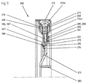
- a second embodiment of a torsional vibration damper according to the invention 200 takes you to the figures 3 and 4.
- the torsional vibration damper a drive-side holding plate 212 and a driven-side holding plate 230, which together form the secondary element and a support plate 201, which together with a hub plate 213 forms a primary element.
- Friction pads 202 provided, which in corresponding slide openings 261 are arranged and which by means of disc spring 214 and retaining ring 215 frictionally against the support plate 201 and the hub plate 213 are held.
- the corresponding Friction surfaces are in the present embodiment by reference numerals 285, 286, 287, 288.
- the corresponding also present in the above embodiment Axial webs and radial webs as well as in the hub plate provided Axialsteg carefully constitutional Artsö réelleen are in the Drawings with the reference numerals 247, 289, 274, 275, 276, 277 characterized.
- the friction device of the present example differs from the according to Figures 1 and 2, characterized in that the slide openings 261 now alone through appropriate breakthroughs are formed in the drive-side holding plate 212.
- the between two shoes 216, 220, 212 provided resilient Coupling not by means of simple coil springs realized, but here is a coaxially arranged coil spring pair, consisting of outer spring 233a, 234a, 235a and Inner spring 233b, 234b, 235b provided.
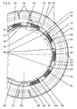
- FIG. 5 shows a drive-side holding plate 312 of the type described above, which has six slide openings 361, 362, 363, 364. All slide openings 361, 362, 363, 364 have the same window length L f0 .
- this gate openings 361, 362, 363, 364 friction pads 302, 302, 304, 305 are used with different Reibklotzines L r0 , L r1 .
- Two of the friction pads 304 have a friction pad length L r0 which is identical to the window length L f0 .
- Four friction pads 302, 303, 304, 305 have a friction pad length L r0 which is smaller than the window length L f0 .
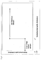
- a torsional vibration damper with such a friction device has the transfer characteristic shown in Figure 6.
- a twist angle which is smaller than the clearance angle ⁇ 1 of the playful Reibklötze 302, 303, 305, only the friction torque of the form-fitting inserted into the slide holes 363 friction pads 304 acts.
- a larger angle of rotation all Reibplötze 302, 303, 304, 305 are effective .
- FIG. 7 shows a further exemplary embodiment of a drive-side holding plate 412 with ten slide openings 461, 462, 463, 464, 465, 466, 467, 468, 469, 470 into which the friction pads 402, 403, 404, 405, 406, 407, 408, 409, 410, 411 are used.
- a uniform window length L f of the slide openings 461, 462, 463, 464, 465, 466, 467, 468, 469, 470 was selected.
- the friction pads 402, 403, 404, 405, 406, 407, 408, 409, 410, 411 have different friction pad lengths L r0 , L r1 , L r2 , L r3 , L r4 , L r5 , so that different clearance angles result, which in the drawing figure with the reference numerals ⁇ 0 , ⁇ 1 , ⁇ 2 , ⁇ 3 , ⁇ 4 , ⁇ 5 are marked.
- FIG. 8 shows a third exemplary embodiment of a drive-side holding plate 512 of a torsional vibration damper.
- friction pads 501, 502, 503, 504, 505 506, 507, 508, 509, 510, 511 are used with uniform Reibklotzharide L r ,
- the friction pad length L r is just half the window length L f1 of the slide opening 566th
Landscapes
- Engineering & Computer Science (AREA)
- General Engineering & Computer Science (AREA)
- Physics & Mathematics (AREA)
- Acoustics & Sound (AREA)
- Aviation & Aerospace Engineering (AREA)
- Mechanical Engineering (AREA)
- Mechanical Operated Clutches (AREA)
Abstract
Description
Es zeigen:
- Figur 1
- ein erstes Ausführungsbeispiel eines erfindungsgemäßen nasslaufenden Torsionsschwingungsdämpfers in Explosionsdarstellung,
- Figur 2
- Stützblech, antriebsseitiges Halteblech und Reibklötze des Torsionsschwingungsdämpfers gemäß der Figur 1 nach der Montage in Draufsicht,
- Figur 3
- ein zweites Ausführungsbeispiel eines erfindungsgemäßen nasslaufenden Torsionsschwingungsdämpfers im Radialhalbschnitt,
- Figur 4
- den nasslaufenden Torsionsschwingungsdämpfer gemäß der Figur 3 im Axialhalbschnitt,
- Figur 5
- ein erstes Ausführungsbeispiel eines antriebsseitigen Halteblechs mit in entsprechende Kulissenöffnungen eingesetzten Reibklötzen eines Torsionsschwingungsdämpfers gemäß den Figuren 1 bis 4,
- Figur 6
- eine Übertragungskennlinie eines erfindungsgemäßen nasslaufenden Torsionsschwingungsdämpfers mit antriebsseitigem Halteblech mit Kulissenöffnungen und Reibklötzen entsprechend der Figur 5,
- Figur 7
- ein zweites Ausführungsbeispiel eines antriebsseitigen Halteblechs mit in entsprechende Kulissenöffnungen eingesetzten Reibklötzen eines Torsionsschwingungsdämpfers gemäß den Figuren 1 bis 4,
- Figur 8
- ein drittes Ausführungsbeispiel eines antriebsseitigen Halteblechs mit in entsprechende Kulissenöffnungen eingesetzten Reibklötzen eines Torsionsschwingungsdämpfers gemäß den Figuren 1 bis 4.
- 100
- Torsionsschwingungsdämpfer
- 101
- Stützblech
- 102
- Reibklotz
- 103
- Reibklotz
- 104
- Reibklotz
- 105
- Reibklotz
- 106
- Reibklotz
- 107
- Reibklotz
- 108
- Reibklotz
- 109
- Reibklotz
- 110
- Reibklotz
- 111
- Reibklotz
- 112
- antriebsseitiges Halteblech (Sekundärelement)
- 113
- Nabenplatte (Primärelement)
- 114
- Tellerfeder
- 115
- Sicherungsring
- 116
- endseitiger Gleitschuh
- 117
- endseitiger Gleitschuh
- 118
- endseitiger Gleitschuh
- 119
- endseitiger Gleitschuh
- 120
- Gleitschuh
- 121
- Gleitschuh
- 122
- Gleitschuh
- 123
- Gleitschuh
- 124
- Gleitschuh
- 125
- Gleitschuh
- 126
- Gleitschuh
- 127
- Gleitschuh
- 128
- Gleitschuh
- 129
- Gleitschuh
- 130
- abtriebsseitiges Halteblech (Sekundärelement)
- 131
- Tellerfeder
- 132
- Eingangsnabe
- 133
- Schraubenfeder
- 134
- Schraubenfeder
- 135
- Schraubenfeder
- 136
- Schraubenfeder
- 137
- Schraubenfeder
- 138
- Schraubenfeder
- 139
- Schraubenfeder
- 140
- Schraubenfeder
- 141
- Schraubenfeder
- 142
- Schraubenfeder
- 143
- Schraubenfeder
- 144
- Schraubenfeder
- 145
- Verzahnung
- 146
- Verzahnung
- 147
- Axialsteg
- 148
- Axialsteg
- 149
- Axialsteg
- 150
- Axialsteg
- 151
- Axialsteg
- 152
- Axialsteg
- 153
- Axialsteg
- 154
- Axialsteg
- 155
- Radialsteg
- 156
- Radialsteg
- 157
- Radialsteg
- 158
- Radialsteg
- 159
- Radialsteg
- 160
- Radialsteg
- 161
- Kulissenöffnung
- 162
- Kulissenöffnung
- 163
- Kulissenöffnung
- 164
- Kulissenöffnung
- 165
- Kulissenöffnung
- 166
- Kulissenöffnung
- 167
- Kulissenöffnung
- 168
- Abstützbügel
- 169
- Abstützbügel
- 170
- Abstützbügel
- 171
- Abstützbügel
- 172
- Abstützbügel
- 173
- Abstützbügel
- 174
- Axialstegdurchführöffnung
- 175
- Axialstegdurchführöffnung
- 176
- Axialstegdurchführöffnung
- 177
- Axialstegdurchführöffnung
- 178
- Axialstegdurchführöffnung
- 179
- Axialstegdurchführöffnung
- 180
- Axialstegdurchführöffnung
- 181
- Axialstegdurchführöffnung
- 182
- Axialstegdurchführöffnung
- 183
- Steckverzahnung
- 184
- Steckverzahnung
- 185
- Reibfläche
- 186
- Reibfläche
- 187
- Reibfläche
- 188
- Reibfläche
- 189
- Radialsteg
- 190
- Radialsteg
- 191
- Radialsteg
- 192
- Radialsteg
- 193
- Radialsteg
- 194
- Radialsteg
- 195
- Radialsteg
- 196
- Radialsteg
- 197
- Verzahnung
- α0
- Freiwinkel
- α1
- Freiwinkel
- Lf
- Fensterlänge
- Lro
- Reibklotzlänge
- Lr1
- Reibklotzlänge
- 200
- Torsionsschwingungsdämpfer
- 201
- Stützblech
- 202
- Reibklotz
- 212
- antriebsseitiges Halteblech (Sekundärelement)
- 213
- Nabenplatte (Primärelement)
- 214
- Tellerfeder
- 215
- Sicherungsring
- 216
- endseitiger Gleitschuh
- 220
- Gleitschuh
- 221
- Gleitschuh
- 230
- abtriebsseitiges Halteblech (Sekundärelement)
- 233a
- Außenfeder
- 233b
- Innenfeder
- 234a
- Außenfeder
- 234b
- Innenfeder
- 235a
- Außenfeder
- 235b
- Innenfeder
- 247
- Axialsteg
- 261
- Kulissenöffnung
- 268
- Abstützbügel
- 270
- Abstützbügel
- 272
- Abstützbügel
- 274
- Axialstegdurchführöffnung
- 275
- Axialstegdurchführöffnung
- 276
- Axialstegdurchführöffnung
- 277
- Axialstegdurchführöffnung
- 282
- Steckverzahnung
- 285
- Reibfläche
- 286
- Reibfläche
- 287
- Reibfläche
- 288
- Reibfläche
- 289
- Radialsteg
- α
- Freiwinkel
- Lf
- Fensterlänge
- Lr
- Reibklotzlänge
- 302
- Reibklotz
- 303
- Reibklotz
- 304
- Reibklotz
- 305
- Reibklotz
- 312
- antriebsseitiges Halteblech (Sekundärelement)
- 361
- Kulissenöffnung
- 362
- Kulissenöffnung
- 363
- Kulissenöffnung
- 364
- Kulissenöffnung
- 368
- Abstützbügel
- α0
- Freiwinkel
- α1
- Freiwinkel
- Lf0
- Fensterlänge
- Lr0
- Reibklotzlänge
- Lr1
- Reibklotzlänge
- 402
- Reibklotz
- 403
- Reibklotz
- 404
- Reibklotz
- 405
- Reibklotz
- 406
- Reibklotz
- 407
- Reibklotz
- 408
- Reibklotz
- 409
- Reibklotz
- 410
- Reibklotz
- 411
- Reibklotz
- 412
- antriebsseitiges Halteblech (Sekundärelement)
- 461
- Kulissenöffnung
- 462
- Kulissenöffnung
- 463
- Kulissenöffnung
- 464
- Kulissenöffnung
- 465
- Kulissenöffnung
- 466
- Kulissenöffnung
- 467
- Kulissenöffnung
- 468
- Kulissenöffnung
- 469
- Kulissenöffnung
- 470
- Kulissenöffnung
- α0
- Freiwinkel
- α1
- Freiwinkel
- α2
- Freiwinkel
- α3
- Freiwinkel
- α4
- Freiwinkel
- α5
- Freiwinkel
- Lf
- Fensterlänge
- Lr0
- Reibklotzlänge
- Lr1
- Reibklotzlänge
- Lr2
- Reibklotzlänge
- Lr3
- Reibklotzlänge
- Lr4
- Reibklotzlänge
- Lr5
- Reibklotzlänge
- 501
- Reibklotz
- 502
- Reibklotz
- 503
- Reibklotz
- 504
- Reibklotz
- 505
- Reibklotz
- 506
- Reibklotz
- 507
- Reibklotz
- 508
- Reibklotz
- 509
- Reibklotz
- 510
- Reibklotz
- 511
- Reibklotz
- 512
- antriebsseitiges Halteblech (Sekundärelement)
- 561
- Kulissenöffnung
- 562
- Kulissenöffnung
- 563
- Kulissenöffnung
- 564
- Kulissenöffnung
- 565
- Kulissenöffnung
- 566
- Kulissenöffnung
- 567
- Kulissenöffnung
- 568
- Kulissenöffnung
- 569
- Kulissenöffnung
- 570
- Kulissenöffnung
- α0
- Freiwinkel
- α1
- Freiwinkel
- α2
- Freiwinkel
- α3
- Freiwinkel
- α4
- Freiwinkel
- α5
- Freiwinkel
- α6
- Freiwinkel
- Lf1
- Fensterlänge
- Lf2
- Fensterlänge
- Lf3
- Fensterlänge
- Lf4
- Fensterlänge
- Lf5
- Fensterlänge
- Lf6
- Fensterlänge
- Lr
- Reibklotzlänge
Claims (17)
- Torsionsschwingungsdämpfer, insbesondere nasslaufender Torsionsschwingungsdämpfer (100, 200),
mit einem mit einer Antriebseinrichtung koppelbarem Primärelement (113, 213),
mit einem relativ zu diesem drehauslenkbaren abtriebsseitig koppelbaren korrespondierenden Sekundärelement (112, 130; 212, 230; 312; 412; 512),
mit einer zwischen Primärelement (113, 213) und Sekundärelement (112, 130; 212, 230; 312; 412; 512) wirksamen Reibvorrichtung,
dadurch gekennzeichnet, dass
das Primärelement (113, 213) und/oder das Sekundärelement (112, 130; 212, 230; 312; 412; 512) Kulissenöffnungen (161, 162, 163, 164, 165, 166, 167; 261; 361, 362, 363, 364; 461, 462, 463, 464, 465, 466, 467,468, 469, 470; 561, 562, 563, 564, 565, 567, 568, 569, 570) aufweist, in welche jeweils wenigstens ein Reibklotz (102, 103, 104, 105, 106, 107, 108, 109, 110, 111; 202; 302, 303, 304, 305; 402, 403, 404, 405, 406, 407, 408, 409, 410, 411; 502, 503, 504, 505, 506, 507, 508, 509, 510, 511, 512) der Reibvorrichtung in der Art eines Kulissensteins eingesetzt ist und
dass sich der wenigstens eine Reibklotz (102, 103, 104, 105, 106, 107, 108, 109, 110, 111; 202; 302, 303, 304, 305; 402, 403, 404, 405, 406, 407, 408, 409, 410, 411; 502, 503, 504, 505, 506, 507, 508, 509, 510, 511, 512) reibschlüssig gegen das korrespondierende Sekundärelement (112, 130; 212, 230; 312; 412; 512) oder Primärelement (113, 213) abstützt. - Torsionsschwingungsdämpfer (100, 200) nach Anspruch 1, dadurch gekenn zeichnet, dass Reibklötze (102, 103, 104, 105, 106, 107, 108, 109, 110, 111; 202; 302, 303, 304, 305; 402, 403, 404, 405, 406, 407, 408, 409, 410, 411; 502, 503, 504, 505, 506, 507, 508, 509, 510, 511, 512) mit unterschiedlichen Reibklotzlängen (Lr, Lr0, Lr1, Lr2, Lr3, Lr4, Lr5) vorgesehen sind.
- Torsionsschwingungsdämpfer (100, 200) nach Anspruch 1 oder 2,
dadurch gekennzeichnet, dass Kulissenöffnungen (161, 162, 163, 164, 165, 166, 167; 261, 262; 361, 362, 363, 364; 461, 462, 463, 464, 465, 466, 467, 468, 469, 470; 561, 562, 563, 564, 565, 566, 567, 568, 569, 570) mit unterschiedlichen Fensterlängen (Lf, Lf0, Lf1, Lf2, Lf3, Lf4, Lf5, Lf6) vorgesehen sind. - Torsionsschwingungsdämpfer (100, 200) nach einem der vorangegangenen Ansprüche,
dadurch gekennzeichnet, dass wenigstens zwei der Kulissenöffnungen (161, 162, 163, 164, 165, 166, 167; 261, 262; 361, 362, 363, 364; 461, 462, 463, 464, 465, 466, 467, 468, 469, 470; 561, 562, 563, 564, 565, 566, 567, 568, 569, 570) in Umfangsrichtung hintereinanderliegend angeordnet sind. - Torsionsschwingungsdämpfer (100, 200) nach einem der vorangegangenen Ansprüche,
dadurch gekennzeichnet, dass die Gesamtlänge (Lr0, Lr + Lr) der in wenigstens eine Kulissenöffnung (161, 162, 163, 164, 165, 166, 167; 261, 262; 361, 362, 363, 364; 461, 462, 463, 464, 465, 466, 467, 468, 469, 470; 561, 562, 563, 564, 565, 566, 567, 568, 569, 570) eingesetzten Reibklötze (304; 407; 507, 508) identisch mit der Fensterlänge (Lf0; Lf; Lf1) der wenigstens einen Kulissenöffnung (363; 466; 566) ist. - Torsionsschwingungsdämpfer (100, 200) nach einem der vorangegangenen Ansprüche,
dadurch gekennzeichnet, dass wenigstens eine der Kulissenöffnungen (161, 162, 163, 164, 165, 166, 167; 261, 262; 361, 362, 363, 364; 461, 462, 463, 464, 465, 466, 467, 468, 469, 470; 561, 562, 563, 564, 565, 566, 567, 568, 569, 570) als Durchgangsöffnung ausgeführt ist und dass der wenigstens eine Reibklotz (102, 103, 104, 105, 106, 107, 108, 109, 110, 111; 202; 302, 303, 304, 305; 402, 403, 404, 405, 406, 407, 408, 409, 410, 411; 502, 503, 504, 505, 506, 507, 508, 509, 510, 511, 512) gegenüberliegende Reibflächen (187, 188; 287, 288) aufweist, mittels derer er (102, 103, 104, 105, 106, 107, 108, 109, 110, 111; 202; 302, 303, 304, 305; 402, 403, 404, 405, 406, 407, 408, 409, 410, 411; 502, 503, 504, 505, 506, 507, 508, 509, 510, 511, 512) sich gegen das korrespondierende Sekundärelement (112, 130; 212, 230; 313; 412; 512) oder das korrespondierende Primärelement reibschlüssig abstützt. - Torsionsschwingungsdämpfer (100, 200) nach einem der vorangegangenen Ansprüche,
dadurch gekennzeichnet, dass wenigstens eine der Kulissenöffnungen als Sackloch ausgeführt ist und dass der wenigstens eine Reibklotz eine auf dem Boden des Sacklochs aufsitzende Gleitfläche aufweist, auf welcher der Reibklotz reibungsarm gleitet sowie eine dieser Gleitfläche gegenüberliegende Reibfläche, mittels derer sich der Reibklotz gegen das korrespondierende Sekundär- und Primärelement reibschlüssig abstützt. - Torsionsschwingungsdämpfer (100, 200) nach Anspruch 6,
dadurch gekennzeichnet, dass das Sekundärelement (112, 130; 212, 230; 312; 412; 512) ein im Wesentlichen ringförmiges antriebsseitiges Halteblech (112, 212, 312, 412, 512) mit einer im Wesentlichen radial verlaufenden Bodenfläche aufweist, welche wenigstens eine der Kulissenöffnungen (161, 162, 163, 164, 165, 166, 167; 261; 361, 362, 363, 364; 461, 462, 463, 464, 465, 466, 467, 468, 469, 470; 561, 562, 563, 564, 565, 566, 567, 568, 569, 570) aufweist. - Torsionsschwingungsdämpfer (100, 200) nach Anspruch 8,
dadurch gekennzeichnet, dass das Primärelement (113, 213) ein ringförmiges Stützblech (101, 201) aufweist, welches antriebsseitig an das antriebsseitige Halteblech (112, 212, 312, 412, 512) anschließt, und an dem sich eine der Reibflächen (188, 288) des wenigstens einen Reibklotzes (102, 103, 104, 105, 106, 107, 108, 109, 110, 111; 202; 302, 303, 304, 305; 402, 403, 404, 405, 406, 407, 408, 409, 410, 411; 502, 503, 504, 505, 506, 507, 508, 509, 510, 511, 512) abstützt, sowie eine Nabenplatte (113, 213), welche abtriebsseitig an das antriebsseitige Halteblech (112, 212, 312, 412, 512) anschließt und an dem sich die andere (187, 287) der beiden Reibflächen (187, 188; 287, 288) des wenigstens einen Reibklotzes (102, 103, 104, 105, 106, 107, 108, 109, 110, 111; 202; 302, 303, 304, 305; 402, 403, 404, 405, 406, 407, 408, 409, 410, 411; 502, 503, 504, 505, 506, 507, 508, 509, 510, 511, 512) abstützt. - Torsionsschwingungsdämpfer (100, 200) nach Anspruch 9,
dadurch gekennzeichnet, dass das Stützblech (101, 201) Axialstege (147, 148, 149, 150, 151, 152, 153, 154; 247) und an diese Axialstege ((147, 148, 149, 150, 151, 152, 153, 154; 247) anschließende Radialstege (189, 190, 191, 192, 193, 194, 195, 196; 289) aufweist, welche das antriebsseitige Halteblech (112, 212, 312, 412, 512) und die Nabenplatte (112, 213) axial durchsetzen und dass eine Tellerfeder (114, 214) zwischen der Nabenplatte (113, 213) und den Radialstegen ((189, 190, 191, 192, 193, 194, 195, 196; 289) angeordnet ist, welche das Stützblech (101, 201) gegen die Nabenplatte (113, 213) und Reibschluss zu den Reibklötzen (102, 103, 104, 105, 106, 107, 108, 109, 110, 111; 202; 302, 303, 304, 305; 402, 403, 404, 405, 406, 407, 408, 409, 410, 411; 502, 503, 504, 505, 506, 507, 508, 509, 510, 511, 512) erzeugend gedrückt hält. - Torsionsschwingungsdämpfer (100, 200) nach Anspruch 10,
dadurch gekennzeichnet, dass ein Sicherungsring (115, 215) vorgesehen ist, welcher zwischen den Radialstegen (189, 190, 191, 192, 193, 194, 195, 196; 289) und der Tellerfeder (114, 214) angeordnet ist und welcher die Tellerfeder (114, 214) reibschlusserzeugend hält. - Torsionsschwingungsdämpfer (100, 200) nach einem der vorangegangenen Ansprüche,
dadurch gekennzeichnet, dass wenigstens einer der Reibklötze (102, 103, 104, 105, 106, 107, 108, 109, 110, 111; 202; 302, 303, 304, 305; 402, 403, 404, 405, 406, 407, 408, 409, 410, 411; 502, 503, 504, 505, 506, 507, 508, 509, 510, 511, 512) Kunststoff enthält. - Torsionsschwingungsdämpfer (100, 200) nach Anspruch 12,
dadurch gekennzeichnet, dass wenigstens einer der Reibklötze (102, 103, 104, 105, 106, 107, 108, 109, 110, 111; 202; 302, 303, 304, 305; 402, 403, 404, 405, 406, 407, 408, 409, 410, 411; 502, 503, 504, 505, 506, 507, 508, 509, 510, 511, 512) ein Kunststoffspitzteil ist. - Torsionsschwingungsdämpfer (100, 200) nach einem der vorangegangenen Ansprüche 12 oder 13,
dadurch gekennzeichnet, dass wenigstens einer der Reibklötze (102, 103, 104, 105, 106, 107, 108, 109, 110, 111; 202; 302, 303, 304, 305; 402, 403, 404, 405, 406, 407, 408, 409, 410, 411; 502, 503, 504, 505, 506, 507, 508, 509, 510, 511, 512) ein Polyamid beihaltet. - Torsionsschwingungsdämpfer (100, 200) nach einem der vorangegangenen Ansprüche,
dadurch gekennzeichnet, dass wenigstens einer der Reibklötze (102, 103, 104, 105, 106, 107, 108, 109, 110, 111; 202; 302, 303, 304, 305; 402, 403, 404, 405, 406, 407, 408, 409, 410, 411; 502, 503, 504, 505, 506, 507, 508, 509, 510, 511, 512) Glasfasern beinhaltet. - Torsionsschwingungsdämpfer (100, 200) nach Anspruch 15,
dadurch gekennzeichnet, dass der Glasfaseranteil zwischen 40 % und 60 %, vorzugsweise 50 % beträgt. - Reibklotz (102, 103, 104, 105, 106, 107, 108, 109, 110, 111; 202; 302, 303, 304, 305; 402, 403, 404, 405, 406, 407, 408, 409, 410, 411; 502, 503, 504, 505, 506, 507, 508, 509, 510, 511, 512) für einen Torsionsschwingungsdämpfer (100, 200) nach einem der vorangegangenen Ansprüche.
Priority Applications (3)
| Application Number | Priority Date | Filing Date | Title |
|---|---|---|---|
| EP03020329A EP1496289B1 (de) | 2003-07-07 | 2003-09-09 | Nasslaufender Torsionsschwingungsdämpfer |
| US10/886,180 US7252593B2 (en) | 2003-07-07 | 2004-07-07 | Torsional-vibration damper |
| KR1020040052759A KR101147438B1 (ko) | 2003-07-07 | 2004-07-07 | 토션 진동 댐퍼와 토션 진동 댐퍼를 위한 마찰블록 |
Applications Claiming Priority (3)
| Application Number | Priority Date | Filing Date | Title |
|---|---|---|---|
| EP20030015283 EP1496287B1 (de) | 2003-07-07 | 2003-07-07 | Antriebsstrang |
| EP03015283 | 2003-07-07 | ||
| EP03020329A EP1496289B1 (de) | 2003-07-07 | 2003-09-09 | Nasslaufender Torsionsschwingungsdämpfer |
Publications (2)
| Publication Number | Publication Date |
|---|---|
| EP1496289A1 true EP1496289A1 (de) | 2005-01-12 |
| EP1496289B1 EP1496289B1 (de) | 2011-10-19 |
Family
ID=33454330
Family Applications (1)
| Application Number | Title | Priority Date | Filing Date |
|---|---|---|---|
| EP03020329A Expired - Lifetime EP1496289B1 (de) | 2003-07-07 | 2003-09-09 | Nasslaufender Torsionsschwingungsdämpfer |
Country Status (3)
| Country | Link |
|---|---|
| US (1) | US7252593B2 (de) |
| EP (1) | EP1496289B1 (de) |
| KR (1) | KR101147438B1 (de) |
Cited By (1)
| Publication number | Priority date | Publication date | Assignee | Title |
|---|---|---|---|---|
| EP1703167A1 (de) | 2005-03-18 | 2006-09-20 | BorgWarner Inc. | Torsionsschwingungsdämpfer |
Families Citing this family (7)
| Publication number | Priority date | Publication date | Assignee | Title |
|---|---|---|---|---|
| US7906268B2 (en) * | 2004-03-18 | 2011-03-15 | Fujifilm Corporation | Positive resist composition for immersion exposure and pattern-forming method using the same |
| US7784595B2 (en) * | 2006-02-13 | 2010-08-31 | Borgwarner Inc. | Integrated clutch assembly damper arrangement |
| DE102006059054B4 (de) * | 2006-12-14 | 2016-09-22 | Borg Warner Inc. | Torsionsschwingungsdämpfer mit Endschuhen |
| DE102006058954A1 (de) * | 2006-12-14 | 2008-06-19 | Borg Warner Inc., Auburn Hills | Gleitschuh für einen Torsionsschwingungsdämpfer, Dividierblech mit einem Gleitschuh und Torsionsschwingungsdämpfer mit einem Gleitschuh |
| US9689451B2 (en) | 2010-02-23 | 2017-06-27 | Renton Coil Spring Co. | Tension spring mount |
| US9944144B2 (en) | 2010-02-23 | 2018-04-17 | Renton Coil Spring Company | Spring and damper systems for attenuating the transmission of energy |
| NL2035123B1 (en) * | 2023-06-19 | 2025-01-06 | Emitech Holding B V | Power take-off damper device |
Citations (7)
| Publication number | Priority date | Publication date | Assignee | Title |
|---|---|---|---|---|
| DE4327017A1 (de) * | 1992-08-20 | 1994-03-24 | Fichtel & Sachs Ag | Torsionsschwingungsdämpfer |
| DE4418390A1 (de) * | 1993-05-26 | 1994-12-01 | Unisia Jecs Corp | Schwungrad mit einer reibungserzeugenden Anordnung |
| EP0641956A1 (de) * | 1993-09-07 | 1995-03-08 | Unisia Jecs Corporation | Torsiondämpfer mit reibungserzeugender Vorrichtung |
| DE19602459A1 (de) * | 1995-01-25 | 1996-08-01 | Unisia Jecs Corp | Schwingungsdämpfungsvorrichtung für Torsionsdämpfer |
| US5597355A (en) * | 1993-11-18 | 1997-01-28 | Unisia Jecs Corporation | Torsional damper with guided friction blocks |
| EP0826899A2 (de) | 1996-08-30 | 1998-03-04 | Aisin Seiki Kabushiki Kaisha | Gleitlagerstütz in einem Zweimassenmechanismus für Kraftdurchleitung |
| EP0922878A2 (de) * | 1997-10-29 | 1999-06-16 | Rohs-Voigt Patentverwertungsgesellschaft mbH | Torsionsschwingungsdämpfer |
Family Cites Families (17)
| Publication number | Priority date | Publication date | Assignee | Title |
|---|---|---|---|---|
| US2855767A (en) | 1952-03-20 | 1958-10-14 | Svenska Rotor Maskiner Ab | Yieldable coupling |
| FR2381944A1 (fr) * | 1977-02-25 | 1978-09-22 | Ferodo Sa | Dispositif amortisseur de torsion, en particulier friction d'embrayage a moyeu amortisseur pour vehicule automobile |
| FR2453335A1 (fr) | 1979-04-02 | 1980-10-31 | Ferodo Sa | Transmission a organe d'accouplement hydraulique et embrayage de verrouillage, notamment pour vehicule automobile |
| US4626226A (en) * | 1980-07-16 | 1986-12-02 | Kabushiki Kaisha Komatsu Seisakusho | Torque fluctuation damper |
| FR2574014B1 (fr) * | 1984-12-05 | 1987-02-20 | Valeo | Dispositif amortisseur de torsion, notamment pour disque de friction d'embrayage de vehicule automobile |
| GB2189865B (en) * | 1986-04-30 | 1989-11-29 | Automotive Products Plc | Torsional vibration damper |
| IT1229120B (it) | 1987-08-14 | 1991-07-22 | Zahnradfabrik Friedrichshafen | Disco di trascinamento cedevole disposo fra un albero motore di un autoveicolo e di un organo di entrata di un cambio di velocita' |
| FR2688564B1 (fr) | 1992-03-10 | 1994-06-24 | Valeo | Double volant amortisseur, notamment pour vehicules automobiles. |
| JPH06129490A (ja) * | 1992-10-16 | 1994-05-10 | Nissan Motor Co Ltd | トーショナルダンパの振動減衰装置 |
| US5342242A (en) | 1993-02-09 | 1994-08-30 | General Motors Corporation | Engine/transmission rotary connection |
| JP3523320B2 (ja) | 1994-03-22 | 2004-04-26 | ヴァレオユニシアトランスミッション株式会社 | 捩り振動低減装置 |
| FR2733809B1 (fr) * | 1995-05-02 | 1997-06-13 | Valeo | Amortisseur de torsion a rondelle de commande, notamment friction d'embrayage pour vehicule automobile |
| JPH11303892A (ja) | 1998-04-17 | 1999-11-02 | Exedy Corp | ダンパーディスク組立体 |
| DE19901043B4 (de) | 1998-07-17 | 2013-01-17 | Zf Friedrichshafen Ag | Kupplungsscheibe für eine Kraftfahrzeug-Reibungskupplung |
| DE10115454A1 (de) | 2001-01-25 | 2002-08-08 | Zf Sachs Ag | Mehrfach-Kupplungseinrichtung, ggf. in Kombination mit einer Torsionsschwingungsdämpferanordnung oder/und einer Elektromaschine |
| JP3683165B2 (ja) | 2000-07-27 | 2005-08-17 | トヨタ自動車株式会社 | トルク変動吸収装置のトルクリミッター部組付け偏芯低減構造および方法 |
| DE10149704A1 (de) | 2001-10-09 | 2003-04-10 | Zf Sachs Ag | Eingangsseitig zentral an einer Drehwelle oder Drehkomponente angebundene Kupplungseinrichtung in einem Kraftfahrzeug-Antriebsstrang |
-
2003
- 2003-09-09 EP EP03020329A patent/EP1496289B1/de not_active Expired - Lifetime
-
2004
- 2004-07-07 US US10/886,180 patent/US7252593B2/en not_active Expired - Lifetime
- 2004-07-07 KR KR1020040052759A patent/KR101147438B1/ko not_active Expired - Fee Related
Patent Citations (7)
| Publication number | Priority date | Publication date | Assignee | Title |
|---|---|---|---|---|
| DE4327017A1 (de) * | 1992-08-20 | 1994-03-24 | Fichtel & Sachs Ag | Torsionsschwingungsdämpfer |
| DE4418390A1 (de) * | 1993-05-26 | 1994-12-01 | Unisia Jecs Corp | Schwungrad mit einer reibungserzeugenden Anordnung |
| EP0641956A1 (de) * | 1993-09-07 | 1995-03-08 | Unisia Jecs Corporation | Torsiondämpfer mit reibungserzeugender Vorrichtung |
| US5597355A (en) * | 1993-11-18 | 1997-01-28 | Unisia Jecs Corporation | Torsional damper with guided friction blocks |
| DE19602459A1 (de) * | 1995-01-25 | 1996-08-01 | Unisia Jecs Corp | Schwingungsdämpfungsvorrichtung für Torsionsdämpfer |
| EP0826899A2 (de) | 1996-08-30 | 1998-03-04 | Aisin Seiki Kabushiki Kaisha | Gleitlagerstütz in einem Zweimassenmechanismus für Kraftdurchleitung |
| EP0922878A2 (de) * | 1997-10-29 | 1999-06-16 | Rohs-Voigt Patentverwertungsgesellschaft mbH | Torsionsschwingungsdämpfer |
Non-Patent Citations (1)
| Title |
|---|
| PATENT ABSTRACTS OF JAPAN vol. 1996, no. 02 29 February 1996 (1996-02-29) * |
Cited By (1)
| Publication number | Priority date | Publication date | Assignee | Title |
|---|---|---|---|---|
| EP1703167A1 (de) | 2005-03-18 | 2006-09-20 | BorgWarner Inc. | Torsionsschwingungsdämpfer |
Also Published As
| Publication number | Publication date |
|---|---|
| KR20050006076A (ko) | 2005-01-15 |
| US20050026704A1 (en) | 2005-02-03 |
| EP1496289B1 (de) | 2011-10-19 |
| KR101147438B1 (ko) | 2012-05-21 |
| US7252593B2 (en) | 2007-08-07 |
Similar Documents
| Publication | Publication Date | Title |
|---|---|---|
| DE19834729A1 (de) | Einrichtung zum Dämpfen von Drehschwingungen | |
| DE102004011830A1 (de) | Drehschwingungsdämpfer | |
| WO2007098745A1 (de) | Zahnradanordnung | |
| DE112014005023T5 (de) | Schwungradanordnung | |
| DE102015214841A1 (de) | Drehschwingungsdämpfungsanordnung, insbesondere Tilgerbaugruppe | |
| WO2008074399A1 (de) | Torsionsschwingungsdämpfer mit mehrteiligem primärelement | |
| EP1496289B1 (de) | Nasslaufender Torsionsschwingungsdämpfer | |
| DE2447582A1 (de) | Zahnraederwechselgetriebe mit mehreren vorgelegewellen und einem radial verlagerbaren verteilzahnrad | |
| EP1353086B1 (de) | Torsionsschwingungsdämpfer sowie Versteifungselement für einen solchen | |
| DE102011003030A1 (de) | Kupplungsscheibe für eine Reibungskupplung eines Kraftfahrzeugs | |
| EP1496288B1 (de) | Torsionsschwingungsdämpfer | |
| DE19916871B4 (de) | Dämpfungsscheibenanordnung | |
| WO2013056949A1 (de) | Drehschwingungsdämpfungsanordnung, insbesondere für den antriebsstrang eines fahrzeugs | |
| DE102009002968B4 (de) | Torsionsschwingungsdämpferanordnung, insbesondere in einer Kupplungsscheibe einer Kraftfahrzeugreibungskupplung | |
| EP1626196B1 (de) | Torsionsschwingungsdämpfer, insbesondere für eine Kupplungsscheibe | |
| DE3501466C2 (de) | Torsionsschwingungsdämpfer mit im Verdrehwinkelbereich des Leerlaufsystems wirksamer, drehzahlabhängiger Reibeinrichtung | |
| DE19536513C2 (de) | Schwingungsdämpfer für eine Scheibenkupplung | |
| DE4442091A1 (de) | Torsionsschwingungsdämpfer für eine Kraftfahrzeug-Reibungskupplung | |
| EP1473484B1 (de) | Torsionsschwingungsdämpfer | |
| EP1460303A1 (de) | Torsionsschwingungsdämpfer | |
| DE102016208120A1 (de) | Reibscheibe für einen Kupplungsscheibendämpfer | |
| EP1979647B1 (de) | Torsionsschwingungsdämpfer | |
| DE102021118655A1 (de) | Dämpfungsvorrichtung | |
| DE202019106788U1 (de) | Rutschkupplung mit Mehrflanschtorsionsschwingungsdämpfer für Antriebsstrang eines Kraftfahrzeugs | |
| DE102019203844A1 (de) | Kupplungsscheibe |
Legal Events
| Date | Code | Title | Description |
|---|---|---|---|
| PUAI | Public reference made under article 153(3) epc to a published international application that has entered the european phase |
Free format text: ORIGINAL CODE: 0009012 |
|
| AK | Designated contracting states |
Kind code of ref document: A1 Designated state(s): AT BE BG CH CY CZ DE DK EE ES FI FR GB GR HU IE IT LI LU MC NL PT RO SE SI SK TR |
|
| AX | Request for extension of the european patent |
Extension state: AL LT LV MK |
|
| 17P | Request for examination filed |
Effective date: 20050201 |
|
| 17Q | First examination report despatched |
Effective date: 20050301 |
|
| AKX | Designation fees paid |
Designated state(s): DE FR GB IT |
|
| RAP1 | Party data changed (applicant data changed or rights of an application transferred) |
Owner name: BORGWARNER INC. |
|
| 17Q | First examination report despatched |
Effective date: 20050301 |
|
| RTI1 | Title (correction) |
Free format text: WET-RUNNING TORSIONAL VIBRATION DAMPER |
|
| GRAP | Despatch of communication of intention to grant a patent |
Free format text: ORIGINAL CODE: EPIDOSNIGR1 |
|
| GRAS | Grant fee paid |
Free format text: ORIGINAL CODE: EPIDOSNIGR3 |
|
| GRAA | (expected) grant |
Free format text: ORIGINAL CODE: 0009210 |
|
| AK | Designated contracting states |
Kind code of ref document: B1 Designated state(s): DE FR GB IT |
|
| REG | Reference to a national code |
Ref country code: GB Ref legal event code: FG4D Free format text: NOT ENGLISH |
|
| REG | Reference to a national code |
Ref country code: DE Ref legal event code: R096 Ref document number: 50314019 Country of ref document: DE Effective date: 20111222 |
|
| PLBE | No opposition filed within time limit |
Free format text: ORIGINAL CODE: 0009261 |
|
| STAA | Information on the status of an ep patent application or granted ep patent |
Free format text: STATUS: NO OPPOSITION FILED WITHIN TIME LIMIT |
|
| PG25 | Lapsed in a contracting state [announced via postgrant information from national office to epo] |
Ref country code: IT Free format text: LAPSE BECAUSE OF FAILURE TO SUBMIT A TRANSLATION OF THE DESCRIPTION OR TO PAY THE FEE WITHIN THE PRESCRIBED TIME-LIMIT Effective date: 20111019 |
|
| 26N | No opposition filed |
Effective date: 20120720 |
|
| REG | Reference to a national code |
Ref country code: DE Ref legal event code: R097 Ref document number: 50314019 Country of ref document: DE Effective date: 20120720 |
|
| GBPC | Gb: european patent ceased through non-payment of renewal fee |
Effective date: 20120909 |
|
| PG25 | Lapsed in a contracting state [announced via postgrant information from national office to epo] |
Ref country code: GB Free format text: LAPSE BECAUSE OF NON-PAYMENT OF DUE FEES Effective date: 20120909 |
|
| REG | Reference to a national code |
Ref country code: FR Ref legal event code: PLFP Year of fee payment: 14 |
|
| REG | Reference to a national code |
Ref country code: FR Ref legal event code: PLFP Year of fee payment: 15 |
|
| REG | Reference to a national code |
Ref country code: FR Ref legal event code: PLFP Year of fee payment: 16 |
|
| PGFP | Annual fee paid to national office [announced via postgrant information from national office to epo] |
Ref country code: FR Payment date: 20180817 Year of fee payment: 16 |
|
| PGFP | Annual fee paid to national office [announced via postgrant information from national office to epo] |
Ref country code: DE Payment date: 20190813 Year of fee payment: 17 |
|
| PG25 | Lapsed in a contracting state [announced via postgrant information from national office to epo] |
Ref country code: FR Free format text: LAPSE BECAUSE OF NON-PAYMENT OF DUE FEES Effective date: 20190930 |
|
| REG | Reference to a national code |
Ref country code: DE Ref legal event code: R119 Ref document number: 50314019 Country of ref document: DE |
|
| PG25 | Lapsed in a contracting state [announced via postgrant information from national office to epo] |
Ref country code: DE Free format text: LAPSE BECAUSE OF NON-PAYMENT OF DUE FEES Effective date: 20210401 |