EP1496245A1 - Brennstoffeinspritzventil - Google Patents
Brennstoffeinspritzventil Download PDFInfo
- Publication number
- EP1496245A1 EP1496245A1 EP04014325A EP04014325A EP1496245A1 EP 1496245 A1 EP1496245 A1 EP 1496245A1 EP 04014325 A EP04014325 A EP 04014325A EP 04014325 A EP04014325 A EP 04014325A EP 1496245 A1 EP1496245 A1 EP 1496245A1
- Authority
- EP
- European Patent Office
- Prior art keywords
- fuel injection
- injection valve
- valve according
- curvature
- radii
- Prior art date
- Legal status (The legal status is an assumption and is not a legal conclusion. Google has not performed a legal analysis and makes no representation as to the accuracy of the status listed.)
- Withdrawn
Links
- 239000000446 fuel Substances 0.000 title claims abstract description 86
- 238000002347 injection Methods 0.000 title claims abstract description 59
- 239000007924 injection Substances 0.000 title claims abstract description 59
- 238000002485 combustion reaction Methods 0.000 claims description 34
- 238000007789 sealing Methods 0.000 claims description 14
- 239000000203 mixture Substances 0.000 description 5
- 238000009736 wetting Methods 0.000 description 4
- 230000015572 biosynthetic process Effects 0.000 description 2
- 230000008021 deposition Effects 0.000 description 2
- 238000009434 installation Methods 0.000 description 2
- 238000004519 manufacturing process Methods 0.000 description 2
- 238000010276 construction Methods 0.000 description 1
- 238000013016 damping Methods 0.000 description 1
- 230000001419 dependent effect Effects 0.000 description 1
- 238000011161 development Methods 0.000 description 1
- 230000018109 developmental process Effects 0.000 description 1
- 230000000694 effects Effects 0.000 description 1
- 230000005284 excitation Effects 0.000 description 1
- 230000007257 malfunction Effects 0.000 description 1
- 239000002245 particle Substances 0.000 description 1
- 239000004071 soot Substances 0.000 description 1
- 230000006641 stabilisation Effects 0.000 description 1
- 238000011105 stabilization Methods 0.000 description 1
- XLYOFNOQVPJJNP-UHFFFAOYSA-N water Substances O XLYOFNOQVPJJNP-UHFFFAOYSA-N 0.000 description 1
Images


Classifications
-
- F—MECHANICAL ENGINEERING; LIGHTING; HEATING; WEAPONS; BLASTING
- F02—COMBUSTION ENGINES; HOT-GAS OR COMBUSTION-PRODUCT ENGINE PLANTS
- F02M—SUPPLYING COMBUSTION ENGINES IN GENERAL WITH COMBUSTIBLE MIXTURES OR CONSTITUENTS THEREOF
- F02M61/00—Fuel-injectors not provided for in groups F02M39/00 - F02M57/00 or F02M67/00
- F02M61/16—Details not provided for in, or of interest apart from, the apparatus of groups F02M61/02 - F02M61/14
- F02M61/18—Injection nozzles, e.g. having valve seats; Details of valve member seated ends, not otherwise provided for
- F02M61/1873—Valve seats or member ends having circumferential grooves or ridges, e.g. toroidal
-
- F—MECHANICAL ENGINEERING; LIGHTING; HEATING; WEAPONS; BLASTING
- F02—COMBUSTION ENGINES; HOT-GAS OR COMBUSTION-PRODUCT ENGINE PLANTS
- F02M—SUPPLYING COMBUSTION ENGINES IN GENERAL WITH COMBUSTIBLE MIXTURES OR CONSTITUENTS THEREOF
- F02M51/00—Fuel-injection apparatus characterised by being operated electrically
- F02M51/06—Injectors peculiar thereto with means directly operating the valve needle
- F02M51/0603—Injectors peculiar thereto with means directly operating the valve needle using piezoelectric or magnetostrictive operating means
-
- F—MECHANICAL ENGINEERING; LIGHTING; HEATING; WEAPONS; BLASTING
- F02—COMBUSTION ENGINES; HOT-GAS OR COMBUSTION-PRODUCT ENGINE PLANTS
- F02M—SUPPLYING COMBUSTION ENGINES IN GENERAL WITH COMBUSTIBLE MIXTURES OR CONSTITUENTS THEREOF
- F02M61/00—Fuel-injectors not provided for in groups F02M39/00 - F02M57/00 or F02M67/00
- F02M61/04—Fuel-injectors not provided for in groups F02M39/00 - F02M57/00 or F02M67/00 having valves, e.g. having a plurality of valves in series
- F02M61/08—Fuel-injectors not provided for in groups F02M39/00 - F02M57/00 or F02M67/00 having valves, e.g. having a plurality of valves in series the valves opening in direction of fuel flow
Definitions
- the invention is based on a fuel injection valve according to the preamble of the main claim.
- a fuel injection valve for direct injection of fuel into the combustion chamber of Internal combustion engine is known which an actuator, one of the actuator operable valve needle for actuating a Valve closing body, which together with one at a Valve seat body formed valve seat surface a Sealing seat forms, and at least one injection opening includes, which is formed downstream of the valve seat.
- a flameproof cone is arranged at a downstream end of the fuel injection valve.
- a disadvantage of the above-mentioned document known fuel injection valve is in particular the elaborate production of the flameproof cone, which either manufactured separately and attached to the valve seat body or have a special editing of the Require valve seat body.
- the shape shown on inwardly opening fuel injectors restricted, while many applications open to the outside Require fuel injectors.
- the fuel injection valve according to the invention with the characterizing features of the main claim has In contrast, the advantage that the geometries of Düsen stressess and designed the valve closing body similar are, so that on the one hand a uniformly shaped Mixture cloud injected and on the other hand, the annular gap between the valve closing body and the valve seat surface kept free from fuel residues and the outside surfaces are simultaneously protected against wetting by fuel, so that fuel deposits in these areas avoided can be.
- the radii of curvature of the valve closing body and the Nozzle bodies are ideally of the same number and symmetrical.
- the double skirt discharge geometry formed thereby promotes the formation of secondary vortices in the Combustion chamber, which effectively empty the annular gap at the sealing seat and so also advantageously fuel deposits prevent.
- valve closing body and the nozzle body aligned, sharp edges identify which the injection of a very uniform Allow mixture cloud. Furthermore, the sharp edges promote as shown in FIG. 3C easier chipping possibly glued Soot particles.
- One in the area of the base of the valve closing body arranged depression allows an effective inflow of the Fuel to the sealing seat.
- a rounding of the nozzle body on the inflow side of the Curvature radii of the nozzle body advantageously allows a simpler installation of the fuel injection valve in Cylinder head.
- Fig. 1 shows a schematic sectional view of a Embodiment of an inventively designed Fuel injection valve 1, which in particular for Use as fuel injector for direct Injecting fuel into the combustion chamber of a Internal combustion engine is suitable. In the embodiment it is an outward opening Fuel injection valve 1.
- the fuel injection valve 1 comprises an actuator 2, which in the present embodiment as a piezoelectric actuator 2 is formed.
- the actuator 2 is in an actuator housing 3rd encapsulated for stabilization and supports end in Inlet direction to an abutment 4 and downstream a shoulder 5 off.
- the shoulder 5 is one two-piece valve needle 6 in frictional connection.
- An inflow-side first part 7 of the valve needle 6 supports on the shoulder 5, while a second part 8 downstream of the first part 7 separated from this is arranged.
- the first part 7 of the valve needle 6 is acted upon by a first return spring 9, which between the shoulder 5 and a sealing housing 10 is arranged is.
- the second part 8 of the valve needle 6 is replaced by a second return spring 11 is applied, the spring force is lower than that of the first return spring 9, so that the second part 8 of the valve needle 6 with respect to the first Part 7 can swing through.
- This is at fast-switching Fuel injection valves 1 with piezoelectric actuators 2 for damping and Entprellung the closing movement appropriate.
- the fuel injection valve 1 further comprises a Corrugated pipe seal 12, which the actuator 2 before the Fuel injection valve 1 flowing through the fuel protects.
- the fuel is in the embodiment over a central fuel supply 13 is supplied and flows through a fuel channel 14 in a housing body 15. He will doing to the sealing housing 10 over into a recess 16th an inserted into the housing body 15 nozzle body 17, in which also the second part 8 of the valve needle. 6 is arranged, directed.
- the second part 8 of the valve needle 6 has a with the Valve needle 6 integrally formed or in non-positive connection with this standing Valve closure member 18, which with a on the Nozzle body 17 formed valve seat 19 a Sealing seat forms.
- valve closing body 18 and the Valve seat 19 supporting nozzle body 17 configured so that on the one hand in the combustion chamber of the internal combustion engine injected mixture jet is optimized and on the other hand the deposition of combustion residues in the area of a Annular gaps 20 between the nozzle body 17 and Valve-closing body 18 prevents and on the nozzle body 17th and the valve closing body 18 itself wetting with Fuel is avoided.
- the valve closing body 18 is for this purpose on a surface 21 facing the combustion chamber For example, formed conically and closes in steady or not continuous slope of the nozzle body 17, wherein Edges 22 and 23 of the valve closing body 18 and the Nozzle body 17 in the closed state of Fuel injection valve 1 are flush with each other and as sharp as possible and free of burrs are to produce.
- Fig. 2 shows a partial sectional view the designated in Fig. 1 with II section of the in FIG. 1 illustrated fuel injection valve 1. Same Components are with matching reference numerals Mistake.
- the illustrated Fuel injection valve 1 designed so that on the one hand the shape of the mixture cloud injected into the combustion chamber is optimized for the combustion process and on the other hand the deposition of combustion residues in the annular gap 20 is prevented by the per unit time hosed off Fuel flow to keep constant and malfunction of the Fuel injection valve 1 by reduced flow to avoid.
- valve closing body 18 and the valve seat 19 bearing nozzle body 17 allows.
- Fig. 2 In the left part in Fig. 2 is a first Variant for an inventive Fuel injection valve 1 shown, while the right Part shows a second embodiment variant.
- the combustion chamber of the Internal combustion engine facing surface 24 of the nozzle body 17th tapered executed. Between the surface 24 and the Sealing seat is an angle ⁇ formed, which is about 90 ° is.
- the second variant shows a curved surface 24 on the nozzle body, the angle ⁇ is much smaller than 90 °.
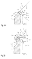
- the different variants as well as the associated valve closing body 18 are in Figs. 3A to 3C enlarged and explained in more detail.
- the edges 22 and 23 of the valve closing body 18 and the Nozzle body 17 are closed Fuel injector 1 flush with each other and are produce as sharp as possible and burr-free.
- a Rounding 32 provided, which simplifies installation of the Fuel injection valve 1 in the cylinder head of Internal combustion engine allowed.
- the rounding 32 is in easy way in the production of the nozzle body for example, produced by turning.
- sealing ring 33 ensures the reliable sealing against the cylinder head of Internal combustion engine.
- the sealing ring 33 can in particular a groove-like recess 34 of the nozzle body 17 is inserted be.
- FIGS. 3A to 3C show an enlarged view of three Embodiments of an inventively designed Fuel injection valve 1 in the area III in Fig. 2nd
- a between the surface 21 and the valve seat 19 and a between the surface 24 and the valve seat 19th trained angle ⁇ should, as already above mentioned, be the same size in all embodiments and maximum 90 °.
- the cross section of the nozzle body 17 and the valve seat surface 19 facing portion 31st the valve closing body 18 and the cross section of the Valve-closing body 18 facing portion 30 of Nozzle body 17 are thus designed similar or im Ideally symmetrical to each other.
- Advantage of this Abspritzgeometrie is a uniformly cone-shaped Mixture cloud and a Abspritzraum, which wetting the surfaces 21 and 24 with fuel and thus the formation prevents deposits from combustion residues.
- the surfaces 21 and 24 are thus spanned by curves with at least one radius of curvature R.
- the surfaces 21 and 24 can also be described by a circle with an infinite inner or outer radius of curvature R i or R a , wherein a center of the applied to the surfaces 21 and 24 Circles thereby either combustion chamber side or valve side of the combustion chamber facing surface boundaries of the surfaces 21 and 24 are to be sought.
- the inner radius of curvature R i centered within the fuel injection valve 1 and the outer radius of curvature R a centered in the combustion chamber are finite, thus leading to curved surfaces 21 and 24 is the inner radius of curvature R i of the valve closing body 18 facing portion 30 of the nozzle body 17 with the nozzle body 17 facing portion 31 of the valve closing body 18 identical and has a common center.
- the outer radii of curvature R a of the nozzle body 17 and the valve closing body 18 are also identical.
- the respective circles with the corresponding radii of curvature R i and R a touch tangentially.
- the injected between the edges 22 and 23 fuel jet is sprayed in an extension of the inner radius of curvature R i in the direction of an arrow 28.
- the circles formed by the radii of curvature R a likewise touch tangentially.
- the injected between the edges 22 and 23 fuel jet is sprayed along a tangent touching both circles in the direction of arrow 28.
- FIGS. 3B and 3C 29 While in the embodiment shown in Fig. 3A the shape of the surfaces 21 and 24 is merely chosen so that wetting the surfaces 21 and 24 with fuel is omitted, the presented in Figs. 3B and 3C Embodiment with curved surfaces 21 and 24 continue advantageous in that secondary vortex in the combustion chamber form the internal combustion engine, which according to the so-called.
- Water jet pump effect the annular gap 20 between the Drain valve closing body 18 and the nozzle body 17, the There still existing fuel, so to speak, in the combustion chamber suck out so that there is no dead volume with the corresponding fuel deposit remains.
- the Secondary vortices are indicated by the arrows in FIGS. 3B and 3C 29 marked.
- the invention is not limited to those shown Embodiments limited and for any forms of Valve closing bodies 18 with and for any construction of fuel injection valves 1 applicable.
Landscapes
- Engineering & Computer Science (AREA)
- Chemical & Material Sciences (AREA)
- Combustion & Propulsion (AREA)
- Mechanical Engineering (AREA)
- General Engineering & Computer Science (AREA)
- Fuel-Injection Apparatus (AREA)
Abstract
Description
- Fig. 1
- einen schematischen Schnitt durch ein erstes Ausführungsbeispiel eines erfindungsgemäßen Brennstoffeinspritzventils in einer Gesamtansicht;
- Fig. 2
- eine vergrößerte schematische Ansicht des abspritzseitigen Teils des in Fig. 1 dargestellten Brennstoffeinspritzventils im Bereich II in Fig. 1 in zwei Ausführungsvarianten;
- Fig. 3A
- eine vergrößerte schematische Ansicht des in Fig. 2 dargestellten erfindungsgemäß ausgestalteten Brennstoffeinspritzventils in einer ersten Ausführungsvariante im Bereich III in Fig. 2,
- Fig. 3B
- eine zweite Ausführungsvariante eines erfindungsgemäßen Brennstoffeinspritzventils in gleicher Ansicht wie Fig. 3A; und
- Fig. 3C
- eine dritte Ausführungsvariante eines erfindungsgemäßen Brennstoffeinspritzventils ebenfalls in gleicher Ansicht wie in Fig. 3A.
Claims (24)
- Brennstoffeinspritzventil (1) zum direkten Einspritzen von Brennstoff in einen Brennraum einer Brennkraftmaschine mit einem Aktor (2) und einer von dem Aktor (2) betätigbaren Ventilnadel (8) zur Betätigung eines Ventilschließkörpers (18), der zusammen mit einer an einem Düsenkörper (17) ausgebildeten Ventilsitzfläche (19) einen Dichtsitz bildet,
dadurch gekennzeichnet, daß ein dem Ventilschließkörper (18) zugewandter Abschnitt (30) des Düsenkörpers (17) und ein dem Düsenkörper (17) zugewandter Abschnitt (31) des Ventilschließkörpers (18) ähnlich geformt sind. - Brennstoffeinspritzventil nach Anspruch 1,
dadurch gekennzeichnet, daß eine dem Brennraum der Brennkraftmaschine zugewandte Fläche (21) des Ventilschließkörpers (18) und eine dem Brennraum der Brennkraftmaschine zugewandte Fläche (24) des Düsenkörpers (17) symmetrisch zueinander sind. - Brennstoffeinspritzventil nach Anspruch 1 oder 2,
dadurch gekennzeichnet, daß die Flächen (21, 24) zumindest einen Krümmungsradius (R) aufweisen. - Brennstoffeinspritzventil nach Anspruch 3,
dadurch gekennzeichnet, daß die Krümmungsradien (R) der Flächen (21, 24) gleich groß sind. - Brennstoffeinspritzventil nach Anspruch 3 oder 4,
dadurch gekennzeichnet, daß die Krümmungsradien (R) der Flächen (21, 24) unendlich sind. - Brennstoffeinspritzventil nach Anspruch 5,
dadurch gekennzeichnet, daß ein zwischen der Fläche (21) und der Ventilsitzfläche (19) und ein zwischen der Fläche (24) und der Ventilsitzfläche (19) ausgebildeter Winkel (α) maximal 90° beträgt. - Brennstoffeinspritzventil nach Anspruch 6,
dadurch gekennzeichnet, daß eine aus den Flächen (21, 24) bestehende Gesamtfläche (25) kegelförmig mit stetiger oder nicht stetiger Steigung ist. - Brennstoffeinspritzventil nach Anspruch 4,
dadurch gekennzeichnet, daß die Krümmungsradien (R) endlich sind. - Brennstoffeinspritzventil nach Anspruch 8,
dadurch gekennzeichnet, daß ein zwischen der Fläche (21) und der Ventilsitzfläche (19) und ein zwischen der Fläche (24) und der Ventilsitzfläche (19) ausgebildeter Winkel (α) viel kleiner als 90° ist. - Brennstoffeinspritzventil nach Anspruch 8 oder 9,
dadurch gekennzeichnet, daß die Flächen (21, 24) durch jeweils einen äußeren Krümmungsradius (Ra) aufgespannt sind. - Brennstoffeinspritzventil nach Anspruch 10,
dadurch gekennzeichnet, daß die äußeren Krümmungsradien (Ra) gleich groß sind. - Brennstoffeinspritzventil nach Anspruch 10 oder 11,
dadurch gekennzeichnet, daß sich die durch die äußeren Krümmungsradien (Ra) gebildeten Kreise tangential berühren. - Brennstoffeinspritzventil nach Anspruch 11,
dadurch gekennzeichnet, daß der in den Brennraum eingespritzte Brennstoff entlang der gemeinsamen Tangente der Kreise eingespritzt wird. - Brennstoffeinspritzventil nach Anspruch 8 oder 9,
dadurch gekennzeichnet, daß die Flächen (21, 24) durch zumindest einen äußeren Krümmungsradius (Ra) und einen inneren Krümmungsradius(Ri) aufgespannt sind. - Brennstoffeinspritzventil nach Anspruch 14,
dadurch gekennzeichnet, daß die äußeren Krümmungsradien (Ra) gleich groß sind und daß die inneren Krümmungsradien (Ri) gleich groß sind. - Brennstoffeinspritzventil nach Anspruch 14 oder 15,
dadurch gekennzeichnet, daß die inneren Krümmungsradien (Ri) des Düsenkörpers (17) und des Ventilschließkörpers (18) einander zugewandt sind. - Brennstoffeinspritzventil nach Anspruch 16,
dadurch gekennzeichnet, daß die durch die inneren Krümmungsradien (Ri) aufgespannten Kreise einen gemeinsamen Mittelpunkt aufweisen. - Brennstoffeinspritzventil nach einem der Ansprüche 14 bis 17,
dadurch gekennzeichnet, daß sich die durch die äußeren Krümmungsradien (Ra) gebildeten Kreise tangential mit dem durch den inneren Krümmungsradius (Ri) berühren. - Brennstoffeinspritzventil nach Anspruch 18,
dadurch gekennzeichnet, daß der in den Brennraum eingespritzte Brennstoff entlang einer Verlängerung des gemeinsamen inneren Krümmungsradius (Ri) eingespritzt wird. - Brennstoffeinspritzventil nach einem der Ansprüche 1 bis 19,
dadurch gekennzeichnet, daß der Düsenkörper (17) und der Ventilschließkörper (18) jeweils eine scharfe Kante (23, 22) aufweisen. - Brennstoffeinspritzventil nach Anspruch 20,
dadurch gekennzeichnet, daß die Kanten (22, 23) bei geschlossenem Brennstoffeinspritzventil (1) bündig aneinander liegen. - Brennstoffeinspritzventil nach einem der Ansprüche 1 bis 21,
dadurch gekennzeichnet, daß der Ventilschließkörper (18) an einer Basis (26) eine rillen- oder nutförmige Vertiefung (27) aufweist. - Brennstoffeinspritzventil nach einem der Ansprüche 1 bis 22,
dadurch gekennzeichnet, daß der Düsenkörper (17) zuströmseitig des Dichtsitzes eine radial äußere Anrundung (32) aufweist. - Brennstoffeinspritzventil nach Anspruch 23,
dadurch gekennzeichnet, daß das Brennstoffeinspritzventil (1) einen Dichtring (33) aufweist, der in einer zuströmseitig der Anrundung (32) ausgebildeten Ausnehmung (34) des Düsenkörpers (17) angeordnet ist.
Applications Claiming Priority (2)
| Application Number | Priority Date | Filing Date | Title |
|---|---|---|---|
| DE2003131266 DE10331266A1 (de) | 2003-07-10 | 2003-07-10 | Brennstoffeinspritzventil |
| DE10331266 | 2003-07-10 |
Publications (1)
| Publication Number | Publication Date |
|---|---|
| EP1496245A1 true EP1496245A1 (de) | 2005-01-12 |
Family
ID=33441704
Family Applications (1)
| Application Number | Title | Priority Date | Filing Date |
|---|---|---|---|
| EP04014325A Withdrawn EP1496245A1 (de) | 2003-07-10 | 2004-06-18 | Brennstoffeinspritzventil |
Country Status (2)
| Country | Link |
|---|---|
| EP (1) | EP1496245A1 (de) |
| DE (1) | DE10331266A1 (de) |
Families Citing this family (1)
| Publication number | Priority date | Publication date | Assignee | Title |
|---|---|---|---|---|
| DE102006003668A1 (de) * | 2006-01-26 | 2007-08-02 | Bayerische Motoren Werke Ag | Brennstoffeinspritzventil mit nach aussen öffnender Düsennadel |
Citations (4)
| Publication number | Priority date | Publication date | Assignee | Title |
|---|---|---|---|---|
| CH217316A (de) * | 1940-04-13 | 1941-10-15 | Saurer Ag Adolph | Mit selbsttätiger Querschnittregelung arbeitende Ringspaltdüse zur Einspritzung von Brennstoff bei Brennkraftmaschinen. |
| US5685492A (en) * | 1990-01-26 | 1997-11-11 | Orbital Engine Company (Australia) Pty. Limited | Fuel injector nozzles |
| US6349885B1 (en) * | 1999-03-12 | 2002-02-26 | Bombardier Motor Corporation Of America | Fuel injector for internal combustion engines and method for making same |
| WO2004016940A1 (de) * | 2002-07-18 | 2004-02-26 | Siemens Aktiengesellschaft | Einspritzventil |
-
2003
- 2003-07-10 DE DE2003131266 patent/DE10331266A1/de not_active Ceased
-
2004
- 2004-06-18 EP EP04014325A patent/EP1496245A1/de not_active Withdrawn
Patent Citations (4)
| Publication number | Priority date | Publication date | Assignee | Title |
|---|---|---|---|---|
| CH217316A (de) * | 1940-04-13 | 1941-10-15 | Saurer Ag Adolph | Mit selbsttätiger Querschnittregelung arbeitende Ringspaltdüse zur Einspritzung von Brennstoff bei Brennkraftmaschinen. |
| US5685492A (en) * | 1990-01-26 | 1997-11-11 | Orbital Engine Company (Australia) Pty. Limited | Fuel injector nozzles |
| US6349885B1 (en) * | 1999-03-12 | 2002-02-26 | Bombardier Motor Corporation Of America | Fuel injector for internal combustion engines and method for making same |
| WO2004016940A1 (de) * | 2002-07-18 | 2004-02-26 | Siemens Aktiengesellschaft | Einspritzventil |
Also Published As
| Publication number | Publication date |
|---|---|
| DE10331266A1 (de) | 2005-03-24 |
Similar Documents
| Publication | Publication Date | Title |
|---|---|---|
| EP1198672B1 (de) | Kraftstoffeinspritzventil für brennkraftmaschinen | |
| EP0980474B1 (de) | Kraftstoffeinspritzdüse für selbstzündende brennkraftmaschinen | |
| DE4039520B4 (de) | Kraftstoff-Einspritzventil | |
| DE19547423B4 (de) | Kraftstoffeinspritzventil für Brennkraftmaschinen | |
| DE69806509T2 (de) | Flache nadel für ein druckbeaufschlagtes dralleinspritzventil | |
| EP2480783B1 (de) | Kraftstoff-einspritzventil für eine brennkraftmaschine | |
| EP1076772A1 (de) | Kraftstoffeinspritzdüse für eine brennkraftmaschine | |
| WO2016082983A1 (de) | GASINJEKTOR MIT NACH AUßEN ÖFFNENDEM VENTILSCHLIEßELEMENT | |
| EP1119703B1 (de) | Brennstoffeinspritzventil | |
| DE602004004056T2 (de) | Einspritzdüse | |
| WO2019092008A1 (de) | Injektor zur eindüsung von gasförmigem kraftstoff | |
| DE102006052817A1 (de) | Brennstoffeinspritzventil | |
| EP2470771B1 (de) | Kraftstoffeinspritzventil | |
| DE10055483B4 (de) | Brennstoffeinspritzventil | |
| EP1408231A1 (de) | Einspritzvorrichtung zum Einspritzen von Kraftstoff | |
| DE69806644T2 (de) | Zylinderkopf für eine verbrennungskraftmaschine | |
| EP1185780B1 (de) | Kraftstoffeinspritzventil für brennkraftmaschinen und ein verfahren zur herstellung desselben | |
| DE102004044820A1 (de) | Brennstoffeinspritzventil | |
| DE102015106760A1 (de) | Eingeschränkte strömungspassage bei common-rail-injektoren | |
| WO2017114634A1 (de) | Brennstoffeinspritzventil | |
| EP1496245A1 (de) | Brennstoffeinspritzventil | |
| DE19941709A1 (de) | Gebautes Steuerventil für einen Injektor eines Kraftstoffeinspritzsystems für Brennkraftmaschinen | |
| DE112017002148B4 (de) | Taschenlose Kraftstoffdüse umfassend eine Anordnung mit einer vorstehenden Spitze | |
| EP3999735B1 (de) | Kraftstoffinjektor | |
| WO2003093669A1 (de) | Kraftstoffeinspritzventil für brennkraftmaschinen |
Legal Events
| Date | Code | Title | Description |
|---|---|---|---|
| PUAI | Public reference made under article 153(3) epc to a published international application that has entered the european phase |
Free format text: ORIGINAL CODE: 0009012 |
|
| AK | Designated contracting states |
Kind code of ref document: A1 Designated state(s): AT BE BG CH CY CZ DE DK EE ES FI FR GB GR HU IE IT LI LU MC NL PL PT RO SE SI SK TR |
|
| AX | Request for extension of the european patent |
Extension state: AL HR LT LV MK |
|
| 17P | Request for examination filed |
Effective date: 20050712 |
|
| AKX | Designation fees paid |
Designated state(s): DE FR GB IT |
|
| 17Q | First examination report despatched |
Effective date: 20060619 |
|
| R17C | First examination report despatched (corrected) |
Effective date: 20060619 |
|
| STAA | Information on the status of an ep patent application or granted ep patent |
Free format text: STATUS: THE APPLICATION IS DEEMED TO BE WITHDRAWN |
|
| 18D | Application deemed to be withdrawn |
Effective date: 20080603 |