EP1496224B1 - Dispositif de commande de la combustion d'un moteur à combustion interne - Google Patents
Dispositif de commande de la combustion d'un moteur à combustion interne Download PDFInfo
- Publication number
- EP1496224B1 EP1496224B1 EP04016122A EP04016122A EP1496224B1 EP 1496224 B1 EP1496224 B1 EP 1496224B1 EP 04016122 A EP04016122 A EP 04016122A EP 04016122 A EP04016122 A EP 04016122A EP 1496224 B1 EP1496224 B1 EP 1496224B1
- Authority
- EP
- European Patent Office
- Prior art keywords
- combustion
- exhaust gas
- temperature
- gas purifier
- engine
- Prior art date
- Legal status (The legal status is an assumption and is not a legal conclusion. Google has not performed a legal analysis and makes no representation as to the accuracy of the status listed.)
- Expired - Fee Related
Links
Images


Classifications
-
- F—MECHANICAL ENGINEERING; LIGHTING; HEATING; WEAPONS; BLASTING
- F02—COMBUSTION ENGINES; HOT-GAS OR COMBUSTION-PRODUCT ENGINE PLANTS
- F02D—CONTROLLING COMBUSTION ENGINES
- F02D41/00—Electrical control of supply of combustible mixture or its constituents
- F02D41/30—Controlling fuel injection
- F02D41/38—Controlling fuel injection of the high pressure type
- F02D41/40—Controlling fuel injection of the high pressure type with means for controlling injection timing or duration
-
- F—MECHANICAL ENGINEERING; LIGHTING; HEATING; WEAPONS; BLASTING
- F02—COMBUSTION ENGINES; HOT-GAS OR COMBUSTION-PRODUCT ENGINE PLANTS
- F02D—CONTROLLING COMBUSTION ENGINES
- F02D41/00—Electrical control of supply of combustible mixture or its constituents
- F02D41/02—Circuit arrangements for generating control signals
- F02D41/021—Introducing corrections for particular conditions exterior to the engine
- F02D41/0235—Introducing corrections for particular conditions exterior to the engine in relation with the state of the exhaust gas treating apparatus
- F02D41/027—Introducing corrections for particular conditions exterior to the engine in relation with the state of the exhaust gas treating apparatus to purge or regenerate the exhaust gas treating apparatus
-
- F—MECHANICAL ENGINEERING; LIGHTING; HEATING; WEAPONS; BLASTING
- F02—COMBUSTION ENGINES; HOT-GAS OR COMBUSTION-PRODUCT ENGINE PLANTS
- F02D—CONTROLLING COMBUSTION ENGINES
- F02D41/00—Electrical control of supply of combustible mixture or its constituents
- F02D41/30—Controlling fuel injection
- F02D41/38—Controlling fuel injection of the high pressure type
- F02D41/40—Controlling fuel injection of the high pressure type with means for controlling injection timing or duration
- F02D41/402—Multiple injections
- F02D41/403—Multiple injections with pilot injections
-
- F—MECHANICAL ENGINEERING; LIGHTING; HEATING; WEAPONS; BLASTING
- F02—COMBUSTION ENGINES; HOT-GAS OR COMBUSTION-PRODUCT ENGINE PLANTS
- F02D—CONTROLLING COMBUSTION ENGINES
- F02D2200/00—Input parameters for engine control
- F02D2200/02—Input parameters for engine control the parameters being related to the engine
- F02D2200/08—Exhaust gas treatment apparatus parameters
- F02D2200/0802—Temperature of the exhaust gas treatment apparatus
-
- F—MECHANICAL ENGINEERING; LIGHTING; HEATING; WEAPONS; BLASTING
- F02—COMBUSTION ENGINES; HOT-GAS OR COMBUSTION-PRODUCT ENGINE PLANTS
- F02D—CONTROLLING COMBUSTION ENGINES
- F02D41/00—Electrical control of supply of combustible mixture or its constituents
- F02D41/02—Circuit arrangements for generating control signals
- F02D41/021—Introducing corrections for particular conditions exterior to the engine
- F02D41/0235—Introducing corrections for particular conditions exterior to the engine in relation with the state of the exhaust gas treating apparatus
- F02D41/027—Introducing corrections for particular conditions exterior to the engine in relation with the state of the exhaust gas treating apparatus to purge or regenerate the exhaust gas treating apparatus
- F02D41/0275—Introducing corrections for particular conditions exterior to the engine in relation with the state of the exhaust gas treating apparatus to purge or regenerate the exhaust gas treating apparatus the exhaust gas treating apparatus being a NOx trap or adsorbent
- F02D41/028—Desulfurisation of NOx traps or adsorbent
-
- F—MECHANICAL ENGINEERING; LIGHTING; HEATING; WEAPONS; BLASTING
- F02—COMBUSTION ENGINES; HOT-GAS OR COMBUSTION-PRODUCT ENGINE PLANTS
- F02D—CONTROLLING COMBUSTION ENGINES
- F02D41/00—Electrical control of supply of combustible mixture or its constituents
- F02D41/02—Circuit arrangements for generating control signals
- F02D41/021—Introducing corrections for particular conditions exterior to the engine
- F02D41/0235—Introducing corrections for particular conditions exterior to the engine in relation with the state of the exhaust gas treating apparatus
- F02D41/027—Introducing corrections for particular conditions exterior to the engine in relation with the state of the exhaust gas treating apparatus to purge or regenerate the exhaust gas treating apparatus
- F02D41/029—Introducing corrections for particular conditions exterior to the engine in relation with the state of the exhaust gas treating apparatus to purge or regenerate the exhaust gas treating apparatus the exhaust gas treating apparatus being a particulate filter
-
- Y—GENERAL TAGGING OF NEW TECHNOLOGICAL DEVELOPMENTS; GENERAL TAGGING OF CROSS-SECTIONAL TECHNOLOGIES SPANNING OVER SEVERAL SECTIONS OF THE IPC; TECHNICAL SUBJECTS COVERED BY FORMER USPC CROSS-REFERENCE ART COLLECTIONS [XRACs] AND DIGESTS
- Y02—TECHNOLOGIES OR APPLICATIONS FOR MITIGATION OR ADAPTATION AGAINST CLIMATE CHANGE
- Y02T—CLIMATE CHANGE MITIGATION TECHNOLOGIES RELATED TO TRANSPORTATION
- Y02T10/00—Road transport of goods or passengers
- Y02T10/10—Internal combustion engine [ICE] based vehicles
- Y02T10/40—Engine management systems
Definitions
- the present invention relates to a combustion control apparatus for an internal combustion engine according to the preamble of independent claim 1 and a combustion control method for an internal combustion engine according to the preamble of independent claim 13.
- a combustion control apparatus for an internal combustion engine according to the preamble of independent claim 1 and a combustion control method for an internal combustion engine according to the preamble of independent claim 13.
- Such an apparatus and such a method can be taken from the prior art document WO 02/066813 A1 .
- the prior art document EP 0 887 535 A2 teaches an engine control apparatus that ensures a vehicle responds in accordance with a driver's expectations during negative pressure control (or boost control).
- a negative pressure control target intake air flow rate is calculated. This air flow rate ensures that the pressure in a cylinder does not drop too low (which could increase oil leakage into the cylinder).
- a greater one of an ISC (idle speed control) target torque and a negative pressure control target intake air flow rate torque-converted value is selected.
- the selected torque is set as an engine demand torque.
- the engine demand torque is combined with a driver demand torque to calculate a target torque.
- the throttle valve is controlled in an electronic manner based on the target torque.
- a combustion control apparatus for an internal combustion engine having an exhaust gas purifier in an exhaust passage, comprising a controller that controls supply of fuel and air to the engine, the controller being configured to produce preliminary combustion at or near compression top dead center and main combustion after an end of the preliminary combustion under a predetermined condition based on a condition of the exhaust gas purifier, the controller being further configured to determine a target intake air quantity by adding an increase correction to the target intake air quantity based on a torque correction value and determine a target fuel injection quantity by calculating the target fuel injection quantity from an actual air quantity and a target air/fuel ratio.
- a combustion control method for an internal combustion engine having an exhaust gas purifier disposed in an exhaust passage comprising producing preliminary combustion at or near compression top dead center and main combustion after an end of the preliminary combustion under a predetermined condition based on a condition of the exhaust gas purifier, and determining a target intake air quantity by adding an increase correction to the target intake air quantity based on a torque correction value and determining a target fuel injection quantity by calculating the target fuel injection quantity from an actual air quantity and a target air/fuel ratio.
- FIG. 1 an internal combustion engine (herein shown as diesel engine) according to an embodiment of the present teaching will be described.
- Diesel engine 1 has at intake passage 2 an intake compressor of variable nozzle type turbocharger 3 so that intake air is supercharged by the compressor and cooled at intercooler 4, then passes intake throttle valve 5 and thereafter flows through collector 6 into a combustion chamber of each cylinder.
- Fuel is pressurized and delivered to common rail 8 by a common rail type fuel injection system, namely, by high-pressure fuel pump 7 and injected directly into a combustion chamber from fuel injector 9 of each cylinder. A mixture of air drawn into the combustion chamber and fuel injected is burned by compression ignition, and exhaust gas is discharged into exhaust passage 10.
- a part of exhaust gas discharged into exhaust passage 10 is returned through EGR passage 11 to an intake side by way of EGR valve 12.
- the remaining of the exhaust gas passes an exhaust turbine of variable nozzle type turbocharger 3 to drive the same.
- NOx trap catalyst 13 downstream of the exhaust gas turbine in exhaust passage 10 is disposed NOx trap catalyst 13 that traps NOx in the exhaust gas when an exhaust air/fuel ratio is lean and purging the trapped NOx when the exhaust air/fuel ratio is rich. Further, NOx trap catalyst 13 carries an oxidation catalyst (noble metal) so as to have a function of oxidizing exhaust components (HC, CO) flowing thereinto.
- DPF 14 downstream of NOx trap catalyst 13 is disposed diesel particulate filter (hereinafter also referred to as DPF) 14.
- DPF 14 also carries an oxidation catalyst (noble metal) so as to have a function of oxidizing exhaust gas components (HC, CO) flowing thereinto.
- oxidation catalyst noble metal
- NOx trap catalyst 13 and DPF 14 may be disposed reversely, and the DPF may carries thereon the NOx trap catalyst so as to constitute an integral unit.
- Inputted to control unit 20 for controlling engine 1 are signals from engine speed sensor 21 for detecting engine speed Ne, accelerator opening degree sensor 21 for detecting accelerator opening degree APO, airflow meter 23 for detecting an intake air quantity Qac and water temperature sensor 24 for detecting cooling water temperature Tw.
- catalyst temperature sensor 25 for detecting the temperature (catalyst temperature) of NOx trap catalyst 13.
- exhaust pressure sensor 26 for detecting an exhaust pressure at an inlet side of DPF 14 of exhaust passage 10
- DPF temperature sensor 27 for detecting the temperature (DPF temperature) of DPF 14
- air/fuel ratio sensor 28 for detecting an exhaust air fuel ratio (hereinafter referred to as exhaust ⁇ and its numerical value is represented by an excess air ratio) at an outlet side of DPF 14, and signals from those sensors are also inputted to control unit 20.
- exhaust ⁇ exhaust air fuel ratio
- the temperature of NOx trap catalyst 13 and the temperature of DPP 14 may be detected indirectly from the exhaust gas temperature by means of exhaust gas temperature sensors (not shown) disposed downstream of NOx trap catalyst 13 and DPF 14.
- control unit 20 Based on those signals, control unit 20 outputs a fuel injection instruction signal to fuel injector 9 for controlling a fuel injection quantity and a fuel injection timing of each fuel injector 9, an opening degree instruction signal to intake throttle valve 5, an opening degree instruction signal to EGR valve 12, etc.
- control unit 20 executes an exhaust purifying control including a control for regeneration of DPF 14 by burning off PM trapped by and accumulated on DPF 14, a control for purging NOx trapped by NOx trap catalyst 13 and a control for releasing S(sulfur)-poisoning of NOx trap catalyst 13, and such an exhaust gas purifying control will be described in detail hereinafter.
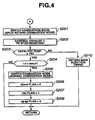
- FIGS. 2 to 12 are flowcharts showing an exhaust purifying control that is executed in control unit 20.
- step S1 various sensor signals are read to detect engine speed Ne, accelerator opening degree APO, intake air quantity Qac, catalyst temperature, DPF inlet side pressure, DPF temperature, DPF outlet side temperature and DPF outlet side exhaust ⁇ .
- step S2 it is determined whether or not NOx trap catalyst 13 in the exhaust system is in a cold condition or in a hot condition.
- the catalyst temperature is equal to or lower than T5 which is an activation temperature of NOx trap catalyst 13, it is determined that NOx trap catalyst 13 is in a cold condition, and the processing goes to a control for a warm-up promoting mode in FIG. 12 which will be described later.
- the processing goes to step S3.
- a NOx amount i.e. an amount of NOx trapped by and accumulated on NOx trap catalyst 13 is calculated.
- the amount of NOx may be estimated from a cumulative value of engine speed (i.e., cumulative value of number of revolution of crankshaft) or running distance. In case a cumulative value is use, the cumulative value is reset at the time when NOx purge is completed (including the time when NOx purge is attained together with S-poisoning release).
- step S4 sulfur accumulation amount (hereinafter referred to simply as S amount) that is an amount of sulfur accumulated on NOx trap catalyst 13 due to S-poisoning is calculated.
- S amount can be estimated from a cumulative value of engine speed or running distance. In case a cumulative value is used, the cumulative value is reset when s-poisoning release is completed.
- a PM amount i.e., an amount of PM trapped by and accumulated on DPF 14 is calculated in the following manner.
- the DPF outlet side exhaust pressure increases naturally.
- the DPF outlet side exhaust pressure is detected by exhaust pressure sensor 26 and compared with a standard exhaust pressure, thereby estimating the PM amount.
- it will do to estimate the PM amount by combining a cumulative value of engine speed or running distance from the previous regeneration of DPF 14 and the exhaust pressure.
- step S7 it is determined whether or not a desul flag indicating that S-poisoning release is in progress is set.
- the desul flag is set (- 1), the processing goes to a control for a S-poisoning release mode in FIG. 4 which will be described later.
- step S8 it is determined whether or not an sp flag indicating that a rich spike mode for purging NOx trap of NOx trap catalyst 13 is in progress is set.
- step 9 it is determined whether a rec flag indicating that a fusion damage preventing mode after regeneration of DPF 14 and s-poisoning release is in progress is set.
- step S11 it is determined whether or not the rq-desul flag indicating that S-poisoning release is requested is set.
- the processing goes to the flow in FIG. 8 which will be described later where it is determined a priority order for regeneration in case S-poisoning release is requested.
- step S12 it is determined whether or not the PM amount of DPF 14 calculated in step S5 exceeds PM1 and it is the time to regenerate DPF 14.
- step S13 it is determined whether or not the S amount of NOx trap catalyst 13 calculated in step S4 exceeds a predetermined amount S1 and it is the time to release S-poisoning.
- step S14 it is determined whether or not the NOx amount of NOx trap catalyst 13 calculated in step S3 exceeds a predetermined amount NOx1 and it is the time to purge the NOx trap.
- step S101 for regeneration of DPF 14, the combustion mode of the engine is switched from a normal lean combustion mode to a split retard combustion mode according to the present teaching invention.
- the split retard combustion mode according to the present teaching will be described.
- the split retard combustion mode is used for, other than regeneration of DPF 14, S-poisoning release, purging of NOx trap (rich spike) and promotion of engine warm-up,
- pilot injection timing is BTDC 40 to 10° and the pilot injection quantity is 1 to 3 mm 3 /st.
- the main injection timing is abut BTDC 10 to -20° and the interval between the pilot injection and the main injection is set to be about 10 to 30° CA.
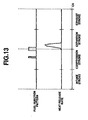
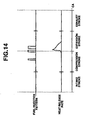
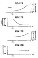
- unexamined Japanese Patent Publication No. 2000-320386 realizes low and high exhaust temperature by splitting the main injection and thereby expanding the limits of retard (refer to the second example of FIG. 14 ).
- main combustion for generating a main torque and preliminary combustion prior to the main combustion are performed as shown in FIG. 15 .
- fuel injections (a, b) are controlled so as to cause the preliminary combustion to occur near compression top dead center (TDC) and the main combustion to start after the preliminary combustion is completely finished.
- injection (a) of fuel is performed during compression stroke for thereby performing the preliminary combustion for elevating incylinder temperature adjacent TDC (compression end temperature).
- the injection quantity of fuel for generating heat of the preliminary combustion varies depending upon a variation of the engine operating condition, at least such a quantity of fuel is injected that enables generation of heat by the preliminary combustion to be perceived and the incylinder temperature at the time of fuel injection for the main combustion to be higher than a self-ignitable temperature.
- the stability of the preliminary combustion can be improved.
- injection (b) of fuel for the main combustion is performed after TDC so that the main combustion starts after the preliminary combustion is completely finished.
- the retard limit of the main combustion is expanded for thereby improving the controllability in control of the exhaust gas temperature to a target temperature, while on the other hand, by injecting fuel for the main combustion after the preliminary combustion is completely finished, a period of time for retard of ignition for the main combustion is attained thereby making higher the rate of premixed combustion in the main combustion and suppressing smoke emission.
- the interval between a combustion start timing of the preliminary combustion and a combustion start timing of the main combustion is at least 20 ° CA though varies depending upon a variation of engine speed since if not, the preliminary combustion (the heat release by the preliminary combustion) is not finished completely.
- the combustion speed is very slow so that the main combustion is finished at ATDC 50 ° or later. By retarding the combustion end timing of the main combustion as much as possible, the main combustion becomes slow, thus making it possible to suppress deterioration in combustion noise.
- the split retard combustion of the present teaching By realizing the split retard combustion of the present teaching , as indicated by 3 in FIG. 16 , combustion of a high exhaust gas temperature and low smoke emission can be attained even when a rich condition is realized, as compared with the first and second examples of FIGS 13 , 14 indicated by 1, 2, respectively. Further, the split retard combustion of this invention exhibits a very low HC concentration.
- retard of the timing of the main combustion increases the ratio of premixed combustion in the main combustion, so that even under a condition where ⁇ is small, the more the timing of the main combustion is retarded, the more smoke emission is suppressed. Further, if the timing of the main combustion is retarded, a higher exhaust temperature can be realized. Thus, by changing the fuel injection timing for the main combustion, the exhaust temperature can be controlled.
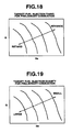
- FIG. 18 shows a target fuel injection timing for the preliminary combustion by using an engine operating condition (engine speed Ne and load Q) as a parameter.
- FIG. 19 shows a target fuel injection quantity for the preliminary combustion by using an engine operating condition (engine speed Ne and load Q) as a parameter.
- FIG. 20 shows a target fuel injection timing (main injection timing) for realizing a certain target exhaust gas temperature by using an engine operating condition (engine speed Ne and load Q) as a parameter.
- the target fuel injection quantity for the main combustion is determined, for correction of toque, in the manner as will be described later.
- step S1101 fuel of a fuel injection quantity for the preliminary combustion (refer to FIG. 19 ) is injected at the fuel injection timing for the preliminary combustion (refer to FIG. 18 ). Then, in step S1102, fuel injection for the main combustion is performed at a retarded fuel injection timing (refer to FIG. 20 ).
- step S102 After the combustion mode of the engine is switched from the normal lean combustion mode to the split retard combustion mode of the present teaching for regeneration of DPF in step S101, the processing goes to step S102.
- step S102 the exhaust ⁇ is controlled to a target value.
- the target value of exhaust ⁇ varies depending upon a variation of the PM amount. Accordingly, the exhaust pressure at the DPF inlet side is detected and compared with a reference exhaust pressure at the engine operating condition (engine speed Ne and load Q), thereby estimating the PM amount, determining a target ⁇ corresponding to the PM amount shown in FIG. 23 and controlling the exhaust ⁇ to the target value.
- Control to the target ⁇ is performed while making torque correction since the torque is lowered by the retard combustion.
- step S103 it is determined whether or not the temperature of DPP exceeds a target upper limit T22.
- step S110 the fuel injection timing of the main combustion is advanced to lower the exhaust gas temperature.
- step S104 it is determined whether or not the temperature of DPF 14 is lower than a target lower limit T21.
- step S109 the fuel injection timing of the main combustion is retarded to raise the exhaust gas temperature.
- step S105 it is determined whether or not a predetermined time t dpfreg has elapsed from start of DPF regeneration. If the predetermined time has elapsed, PM accumulated on DPF 14 is burned off completely, so the processing goes to step S106.
- step S106 the combustion mode is switched from the split retard combustion mode of the present teaching to the normal combustion mode to stop heating of DPF 14 since DPF regeneration is completed.
- step S201 for releasing the S-poisoning of NOx trap catalyst 13, the combustion mode of the engine is switched from the normal lean combustion mode to the split retard combustion mode of the present teaching .
- step s202 the exhaust ⁇ is controlled to stoichiometric. Namely, the exhaust ⁇ is controlled by setting the target exhaust ⁇ at stoichiometric. Control to the target exhaust ⁇ , though will be described in detail later, is executed while performing torque correction since the retard combustion causes the torque to be lowered.
- step S203 it is determined whether or not the catalyst temperature is higher than a predetermined temperature T4.
- T4 is set at 600 °C since in case of NOx trap catalyst of Ba the atmosphere of rich to stoichiometric needs to be 600 °C or higher.
- step S210 the fuel injection timing of the main combustion is retarded to raise the exhaust gas temperature.
- step S204 it is determined whether or not a predetermined time t desul has elapsed from the start of the S-poisoning release mode. If the predetermined time has elapsed, it is determined that the S-poisoning release is completed and the processing goes to step S205.
- step s205 since the S-poisoning release is completed, the combustion mode is switched from the split retard combustion mode of the present teaching to the normal combustion mode to stop heating of NOx trap catalyst 13. Of course, the stoichiometric operation is cancelled at the same time.
- NOx purge is caused at the same time since the NOx trap catalyst is exposed to stoichiometric. Thus, this is for canceling a NOx purge request (rich spike request) if having been made.
- the rich spike mode (NOx purge mode) of FIG. 5 will be described.
- step S301 for the NOx purge of NOx trap catalyst 13, the combustion mode of the engine is switched from the normal lean combustion mode to the split retard combustion mode of the present teaching .
- step S302 the exhaust ⁇ is controlled to rich. Namely, the exhaust ⁇ is controlled by setting the target ⁇ to rich. Control to the target ⁇ , which will be described in detail later, is performed while making torque correction since the torque is lowered by the retard combustion.
- step S303 it is determined whether or not a predetermined time t spike has elapsed from the start of the rich spike mode. If the predetermined time has elapsed, it is determined that the NOx purge is completed and the flow goes to step S304.
- step S304 since the NOx purge is completed, the combustion mode is switched from the split retard combustion mode to the normal combustion mode. Of course, the rich operation is cancelled at the same time.
- step S401 since DPF 14 is still in a high temperature condition immediately after the DPF regeration or the like and therefore rapid control of the exhaust ⁇ to rich may possibly cause the remaining PM of DPF 14 to burn all at once and thereby cause fusion damage, the exhaust ⁇ is controlled to a target value, for example, controlled so that ⁇ ⁇ 1.4.
- the exhaust gas temperature is desired to be low, so that the exhaust ⁇ is controlled to the target value, not by the split retard combustion mode of the present teaching but by the normal combustion mode.
- step S402 it is determined whether or not the temperature of DPF 14 is lower than a predetermined temperature T3 (e.g., 500 °C) at which there is not any possibility of rapid oxidation of the PM. If the temperature of DPF 14 is higher than T3, control of the exhaust ⁇ is continued. If the temperature of DPF 14 becomes lower than T3, damage of DPF 14 can be avoided even if the oxygen concentration becomes equal to that of the atmosphere and therefore the processing flow goes to step S403.
- T3 e.g., 500 °C
- step 403 since there is not any possibility of fusion damage of DPF 14, control of the exhaust ⁇ is finished.
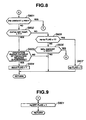
- step S501 by the method similar to step S13, it is determined whether or not the S amount exceeds a predetermined amount S1 and it is the time to release S-poisoning.
- the processing flow of FIG. 8 the priority order is determined.
- step 503 by the technique similar to step S14, it is determined whether or not the NOx amount exceeds a predetermined amount NOx1 and it is the time to purge the NOx trap.
- step S503 If it is determined in step S503 that the NOx amount ⁇ NOx1, this is the case where only the DPF regeneration request is issued, so the processing goes to step S504.
- a range capable of executing DPF regeneration and S-poisoning release i.e., operation range other than low-speed and low-load range, in which an extent of temperature rise is relatively small and an extent of deterioration of exhaust efficiency does not exceed an allowable value.
- step S506 it is determined whether or not the engine is operating under a condition where emission of NOx is small (e.g., steady-state).
- a condition where emission of NOx is small e.g., steady-state.
- step S507 If it is determined in step S507 that the DPF temperature > T6, the processing goes to steps S504 and S505 to give priority to the DPF regeneration.
- step S601 it is determined, after issuance of the S-poisoning cancel request and by the technique similar to step S12, whether or not the PM amount exceeds a predetermined amount PM1 and it is the time to regenerate DPF 14.
- the priority order is determined.
- step S602 it is determined whether or not the catalyst temperature is higher than predetermined temperature T1. If higher, the processing goes to step S603.
- an operation range capable of executing DPF regeneration and S-poisoning release i.e., operation range other than low-speed and low-load range, in which an extent of temperature rise is relatively small and an extent of deterioration of exhaust efficiency does not exceed an allowable value.
- step S602 If it is determined in step S602 that the catalyst temperature ⁇ T1, it is preferable to give priority to NOx purge. This is because even if it is started to raise the temperature of DPF 14, it takes a long time for the catalyst to be heated up to the temperature at which S-poisoning release can be executed and there is a possibility that deterioration of NOx is caused at the tail pipe during raising of the temperature of the catalyst. Accordingly, the processing goes to step S605.
- step S606 If the rq-sp flag is not set, the processing goes to step S606.
- step S606 it is determined, after issuance of the S-poisoning cancel request and by the technique similar to step S14, whether or not the NOx amount exceeds the predetermined value NOx1 and it is the time to purge the NOx trap.
- step S1001 it is determined whether or not the operation of the engine is in an operation range capable of executing a warm-up promoting operation.
- the warm-up promoting operation is executed by the split retard combustion mode of the present teaching , it is determined whether or not the operation of the engine is in the range capable of executing the split retard combustion mode.
- the range capable of executing DPF generation and S-poisoning release shown in FIG. 24 is regarded as the operation range capable of executing the warm-up promoting operation, and if the engine operating condition is in this range, the processing goes to step S1002.
- step S1002 for promotion of warm-up, the combustion mode of the engine is switched from the normal lean combustion to the split retard combustion mode of the present invention.
- the exhaust gas temperature becomes high, thus making it possible to promote warm-up of the catalyst.
- the target ⁇ is set and the exhaust ⁇ is controlled to the target ⁇ .
- Control to the target ⁇ which will be described in detail later, is performed while making torque correction since the torque is lowered by the retard combustion.
- step S1003 it is determined whether or not the catalyst temperature is higher than T5, i.e., its activation temperature. If the catalyst temperature > T5, the processing goes to S1004 to switch the combustion mode from the split retard combustion mode of the present teaching to the normal combustion mode and finish the warm-up promoting operation.
- the retard combustion causes the torque to reduce, so that it is important how to compensate for reduction of the torque while maintaining the target ⁇ . Further, since the more the exhaust gas temperature is raised by retarding the fuel injection timing for the main combustion, the more the torque reduces, so that it is necessary to deal with this problem. Further, particularly in case of the warm-up promoting mode, if the temperatures at portions of the engine are low, the combustion efficiency becomes lower and the torque reduces much more though the fuel injection timing for the main combustion is the same. Thus, it is also necessary to deal with this problem.
- FIG. 25 is a flowchart for intake air quantity control including torque correction.
- step S2001 a requested fuel injection quantity QFDRV equated to a requested engine torque is calculated from accelerator opening degree APO and engine speed Ne.
- step S2002 basic target air quantity tQacb is calculated from target fuel injection quantity QFDRV and target ⁇ .
- the target ⁇ as having described hereinbefore, is determined so as to meet with the DPF generation, S-poisoning release, NOx purge and warm-up acceleration, respectively.
- step S2003 it is determined whether or not the split retard combustion mode is in progress. If the split retard combustion mode is in progress, the processing goes to step S2004.
- a basic torque correction value Ka1 is calculated from the target ⁇ and engine speed Ne and with reference to such a map as shown in FIG. 27 .
- the target ⁇ becomes smaller than 1
- the torque reduces, so that Ka1 is made larger as the target becomes smaller than 1.
- the engine speed Ne becomes higher, a variation of the crank angle is caused even if the combustion time is the same, thus causing the torque to reduce.
- Ka1 is made lager as the engine speed Ne becomes higher.
- a correction coefficient Ka2 for the basic torque correction value is calculated from the fuel injection timing (main injection timing) during the split retard combustion mode. Specifically, with reference to the table shown in FIG. 28 , the correction coefficient Ka2 is made larger as the main injection timing is retarded more. This is because the more the main injection timing is retarded, the more the torque reduces.
- a correction coefficient Ka3 for the basic torque correction value is calculated from a cooling water temperature Tw which is a parameter representative of an engine temperature. Specifically, with reference to the table shown in FIG. 29 , the correction coefficient Ka3 is made larger as the cooling water temperature Tw is lower. This is because the combustion efficiency becomes worse as the cooling water temperature Tw becomes lower, thus more reducing the torque. This correction is effective particularly at the warm-up accelerating mode.
- FIG. 26 shows a flowchart for the fuel injection quantity control.
- step S2101 the actual air quantity Qac is detected by the airflow meter.
- step S2102 the target fuel injection quantity tQF is calculated from the actual air quantity Qac and the target ⁇ .
- step S2103 the fuel injection valve is controlled so as to attain the target fuel injection quantity tQF.
- the target air quantity to be supplied to the engine is corrected so as to increase by the torque correction value and the target fuel injection quantity is calculated from the actual air quantity and the target, thereby controlling the fuel injection valve, whereby reduction of torque can be suppressed while realizing the target ⁇ .
Claims (24)
- Appareil de commande de combustion pour un moteur à combustion interne (1) ayant un épurateur de gaz d'échappement (13, 14) dans un passage d'échappement (10), comprenant un dispositif de commande (5, 11, 9, 20) qui commande l'amenée du carburant et d'air au moteur (1) ;
le dispositif de commande (5, 11, 9, 20) étant configuré pour produire une combustion préliminaire à ou près du point mort haut de compression et une combustion principale après la fin de combustion préliminaire sous une condition prédéterminée basée sur une condition de l'épurateur de gaz d'échappement (13, 14,), et pour déterminer une quantité d'injection de carburant pour la combustion préliminaire de manière à permettre qu'une température dans le cylindre au moment de l'injection du carburant pour la combustion principale soit plus élevée qu'une température d'auto-allumage,
caractérisé en ce que
le dispositif de commande (5, 11, 9, 20) étant configuré en outre pour :déterminer une quantité d'air cible (tQac) en ajoutant une correction d'augmentation à la quantité d'air cible (tQac) basée sur une valeur de correction de couple (Ka),déterminer une quantité d'injection de carburant cible (tQF) en calculant la quantité d'injection de carburant cible (tQF) à partir d'une quantité d'air actuelle (QaC) et d'un rapport air/carburant cible. - Appareil de commande de combustion selon la revendication 1, caractérisé en ce que le dispositif de commande (5, 11, 9, 20) est configuré en outre pour corriger la valeur de correction de couple (Ka) en accord avec un calage de l'injection de carburant pour la combustion principale.
- Appareil de commande de combustion selon la revendication 1 ou 2, caractérisé en ce que le dispositif de commande (5, 11, 9, 20) est configuré en outre pour corriger la valeur de correction de couple (Ka) en accord avec une température du moteur.
- Appareil de commande de combustion selon la revendication 3, caractérisé en ce que le dispositif de commande (5, 11, 9, 20) est configuré en outre pour utiliser une température (Tw) de l'eau de refroidissement comme température du moteur.
- Appareil de commande de combustion selon l'une des revendications 1 à 4, caractérisé en ce que le dispositif de commande (5, 11, 9, 20) est configuré en outre pour calculer une valeur de base (Ka1) de la valeur de correction de couple (Ka) à partir du rapport air/carburant cible et d'une vitesse (Ne) du moteur.
- Appareil de commande de combustion selon l'une des revendications 1 à 5, caractérisé en ce qu'un intervalle entre un instant de début de combustion de la combustion principale et un instant de début de combustion de la combustion préliminaire est égal ou supérieur à 20° dans l'angle du vilebrequin.
- Appareil de commande de combustion selon l'une des revendications 1 à 6, caractérisé en ce qu'un intervalle entre un instant final de combustion de la combustion principale et le point mort haut de compression est égal ou supérieur à 50° dans l'angle du vilebrequin.
- Appareil de commande de combustion selon l'une des revendications 1 à 7, caractérisé en ce que le dispositif de commande (5, 11, 9, 20) est configuré en outre pour commander une température de gaz d'échappement du moteur (1) en faisant varier le calage de l'injection de carburant pour la combustion principale.
- Appareil de commande de combustion selon l'une des revendications 1 à 8, caractérisé en ce que l'épurateur des gaz d'échappement comprend un filtre de matières particulaires (14) pour recueillir les matières particulaires dans les gaz d'échappement, et le dispositif de commande (5, 11, 9, 20) est configuré en outre pour augmenter une température du filtre de matières particulaires (14) pour bruler les matières particulaires qui se sont accumulées sur le filtre de matières particulaires (13) en régénérant ainsi le filtre de matières particulaires (13) sous la condition prédéterminée basée sur la condition de l'épurateur (14) des gaz d'échappement.
- Appareil de commande de combustion selon l'une des revendications 1 à 8, caractérisé en ce que l'épurateur des gaz d'échappement comprend un catalyseur piégeant les NOx pour piéger les NOx dans les gaz d'échappement lorsqu'un rapport air/carburant d'échappement est appauvri, et le dispositif de commande est configuré en outre pour rendre le rapport air/carburant d'échappement plus riche et pour purger les NOx piégés par le catalyseur piégeant les NOx sous la condition prédéterminée basée sur la condition de l'épurateur des gaz d'échappement.
- Appareil de commande de combustion selon l'une des revendications 1 à 8, caractérisé en ce que l'épurateur des gaz d'échappement comprend un catalyseur piégeant les NOx pour piéger les NOx dans les gaz d'échappement lorsqu'un rapport air/carburant d'échappement est appauvri, et le dispositif de commande est configuré en outre pour augmenter une température des gaz d'échappement du moteur et pour libérer l'empoisonnement au souffre du catalyseur piégant les NOx sous la condition prédéterminée basée sur la condition de l'épurateur des gaz d'échappement.
- Appareil de commande de combustion selon l'une des revendications 1 à 11, caractérisé en ce que le dispositif de commande (5, 11, 9, 20) est configuré en outre pour échauffer l'épurateur des gaz d'échappement (13, 14) sous la condition prédéterminée basée sur la condition de l'épurateur des gaz d'échappement, qui est une condition, à savoir que l'épurateur des gaz d'échappement est froid.
- Procédé de commande de combustion pour un moteur à combustion interne (1) comportant un épurateur des gaz d'échappement (13, 14) disposé dans un passage d'échappement (10), le procédé comprenant :la production d'une combustion préliminaire à ou à proximité du point mort haut de compression et de la combustion principale après la fin de la combustion préliminaire sous une condition prédéterminée basée sur une condition de l'épurateur des gaz d'échappement ; etla détermination d'une quantité d'injection de carburant pour la combustion préliminaire de manière à permettre qu'une température dans le cylindre à l'instant de l'injection du carburant pour la combustion principale soit plus élevée qu'une température à auto-allumage ;caractérisé par
la détermination d'une quantité d'air cible (tQac) en ajoutant une correction d'augmentation à la quantité d'air cible (tQac) sur la base d'une valeur de correction de couple (Ka), la détermination d'une quantité d'injection de carburant cible (tQF) en calculant la quantité d'injection de carburant cible (tQF) à partir d'une quantité d'air actuelle (Qac) et d'un rapport air/carburant cible. - Procédé de commande de combustion selon la revendication 13, caractérisé par la correction de la valeur de correction de couple (Ka) en accord avec un calage de l'injection de carburant pour la combustion principale.
- Procédé de commande de combustion selon la revendication 13 ou 14, caractérisé par la correction de la valeur de correction cible (Ka) en fonction d'une température du moteur.
- Procédé de commande de combustion selon la revendication 15, caractérisé dans ce que la correction comprend l'utilisation d'une température (Tw) de l'eau de refroidissement comme température du moteur.
- Procédé de commande de combustion selon la revendication 13 à 16, caractérisé par le calcul d'une valeur de base (Ka1) de la valeur de correction de couple (Ka) à partir du rapport air/carburant cible et d'une vitesse (Ne) du moteur.
- Procédé de commande de combustion selon la revendication 13 à 17, caractérisé en ce qu'un intervalle entre un instant de début de combustion de la combustion principale et un instant de début de combustion de la combustion préliminaire est égal ou supérieur à 20° dans l'angle du vilebrequin.
- Procédé de commande de combustion selon la revendication 13 à 18, caractérisé en ce qu'un intervalle entre un instant final de combustion de la combustion principale et le point mort haut de compression est égal ou supérieur à 50° dans l'angle du vilebrequin.
- Procédé de commande de combustion selon la revendication 13 à 19, caractérisé par le réglage d'une température des gaz d'échappement du moteur (1) en faisant varier le calage de l'injection de carburant pour la combustion principale.
- Procédé de commande de combustion selon l'une des revendications 13 à 20, caractérisé en ce que l'épurateur des gaz d'échappement comprend un filtre de matières particulaires (14) pour recueillir les matières particulaires dans les gaz d'échappement, le procédé comprenant en outre l'augmentation de la température du filtre des matières particulaires (14) pour brûler les matières particulaires qui se sont accumulées sur le filtre de matières particulaires (14) en régénérant ainsi le filtre de matières particulaires (14) sous la condition prédéterminée basée sur la condition de l'épurateur des gaz d'échappement.
- Procédé de commande de combustion selon la revendication 13 à 20, caractérisé en ce que l'épurateur des gaz d'échappement comprend un catalyseur (13) piégeant les NOx pour piéger les NOx dans les gaz d'échappement lorsqu'un rapport air/carburant d'échappement est appauvri, le procédé comprenant en outre l'enrichissement du rapport air/carburant d'échappement et la purge des NOx piégés par le catalyseur (13) piégeant les NOx sous la condition prédéterminée basée sur la condition de l'épurateur des gaz d'échappement.
- Procédé de commande de combustion selon l'une des revendications 13 à 20, caractérisé en ce que l'épurateur des gaz d'échappement comprend un catalyseur (13) piégeant les NOx pour piéger les NOx dans les gaz d'échappement lorsqu'un rapport air/carburant d'échappement est appauvri, le procédé comprenant en outre l'augmentation de la température des gaz d'échappement du moteur (1) et la libération de l'empoisonnement au souffre du catalyseur (13) piégeant les NOx sous la condition prédéterminée basée sur la condition de l'épurateur des gaz d'échappement.
- Procédé de commande de combustion selon la revendication 13 à 20, caractérisé par l'échauffement de l'épurateur des gaz d'échappement (13, 14) sous la condition prédéterminée basée sur la condition de l'épurateur des gaz d'échappement, qui est une condition, à savoir que l'épurateur des gaz d'échappement est froid.
Applications Claiming Priority (4)
| Application Number | Priority Date | Filing Date | Title |
|---|---|---|---|
| JP2003193310 | 2003-07-08 | ||
| JP2003193310 | 2003-07-08 | ||
| JP2003279629 | 2003-07-25 | ||
| JP2003279629A JP2005042661A (ja) | 2003-07-25 | 2003-07-25 | 内燃機関の燃焼制御装置 |
Publications (3)
| Publication Number | Publication Date |
|---|---|
| EP1496224A2 EP1496224A2 (fr) | 2005-01-12 |
| EP1496224A3 EP1496224A3 (fr) | 2005-11-16 |
| EP1496224B1 true EP1496224B1 (fr) | 2008-08-20 |
Family
ID=33455604
Family Applications (1)
| Application Number | Title | Priority Date | Filing Date |
|---|---|---|---|
| EP04016122A Expired - Fee Related EP1496224B1 (fr) | 2003-07-08 | 2004-07-08 | Dispositif de commande de la combustion d'un moteur à combustion interne |
Country Status (3)
| Country | Link |
|---|---|
| EP (1) | EP1496224B1 (fr) |
| CN (1) | CN100520024C (fr) |
| DE (1) | DE602004015894D1 (fr) |
Families Citing this family (3)
| Publication number | Priority date | Publication date | Assignee | Title |
|---|---|---|---|---|
| JP5472406B2 (ja) * | 2012-09-07 | 2014-04-16 | トヨタ自動車株式会社 | 内燃機関の制御システム |
| KR101683488B1 (ko) * | 2013-11-22 | 2016-12-07 | 현대자동차 주식회사 | 린 녹스 트랩의 탈황 장치 및 방법 |
| CN109973175A (zh) * | 2019-03-20 | 2019-07-05 | 一汽解放汽车有限公司 | 柴油机颗粒捕集器再生时的温度控制方法 |
Family Cites Families (7)
| Publication number | Priority date | Publication date | Assignee | Title |
|---|---|---|---|---|
| JPS59194020A (ja) * | 1983-04-19 | 1984-11-02 | Nissan Motor Co Ltd | デイ−ゼルエンジンの排気微粒子処理装置 |
| JPS61197710A (ja) * | 1985-02-27 | 1986-09-02 | Nissan Motor Co Ltd | デイ−ゼルエンジンの排気微粒子処理装置 |
| US5839275A (en) * | 1996-08-20 | 1998-11-24 | Toyota Jidosha Kabushiki Kaisha | Fuel injection control device for a direct injection type engine |
| JP3514077B2 (ja) * | 1997-06-24 | 2004-03-31 | 日産自動車株式会社 | エンジンのスロットル制御装置 |
| DE19747671C1 (de) * | 1997-10-29 | 1999-07-08 | Daimler Chrysler Ag | Verfahren zum Betrieb eines mehrzylindrigen Verbrennungsmotors |
| DE60221913T2 (de) * | 2001-02-20 | 2008-05-08 | Isuzu Motors Ltd. | Kraftstoffinjektionssteuerverfahren für einen Dieselmotor und regeneratives Steuerverfahren für Abgasnach behandlungseinrichtung |
| JP2003065116A (ja) * | 2001-08-24 | 2003-03-05 | Nissan Motor Co Ltd | 内燃機関の排気浄化装置 |
-
2004
- 2004-07-08 EP EP04016122A patent/EP1496224B1/fr not_active Expired - Fee Related
- 2004-07-08 DE DE602004015894T patent/DE602004015894D1/de active Active
- 2004-07-08 CN CNB2004100633405A patent/CN100520024C/zh not_active Expired - Fee Related
Non-Patent Citations (1)
| Title |
|---|
| None * |
Also Published As
| Publication number | Publication date |
|---|---|
| CN1576533A (zh) | 2005-02-09 |
| DE602004015894D1 (de) | 2008-10-02 |
| EP1496224A2 (fr) | 2005-01-12 |
| EP1496224A3 (fr) | 2005-11-16 |
| CN100520024C (zh) | 2009-07-29 |
Similar Documents
| Publication | Publication Date | Title |
|---|---|---|
| JP4158645B2 (ja) | 内燃機関の燃焼制御装置 | |
| US7054734B2 (en) | Combustion control system of internal combustion engine | |
| EP1672204B1 (fr) | Moteur à combustion interne avec filtre à particules dans le système d'échappement | |
| US7007462B2 (en) | Combustion control apparatus for internal combustion engine | |
| US7121083B2 (en) | Combustion control apparatus and method for internal combustion engine | |
| EP1642016B1 (fr) | Dispositif servant a controler la combustion d'un moteur | |
| US6990801B2 (en) | Combustion control apparatus for internal combustion engine | |
| JP2005240757A (ja) | 内燃機関の制御装置 | |
| US6907862B2 (en) | Combustion control apparatus for internal combustion engine | |
| EP1496234B1 (fr) | Dispositif de commande de la combustion d'un moteur à combustion interne | |
| US7334398B2 (en) | Combustion control apparatus and method for internal combustion engine | |
| US20050022513A1 (en) | Combustion control system of internal combustion engine | |
| US20050039444A1 (en) | Combustion control apparatus for internal combustion engine | |
| EP1496235B1 (fr) | Dispositif de commande de la combustion d'un moteur à combustion interne | |
| US7594390B2 (en) | Combustion control apparatus and method for internal combustion engine | |
| EP1496224B1 (fr) | Dispositif de commande de la combustion d'un moteur à combustion interne | |
| JP2005048748A (ja) | 内燃機関の燃焼制御装置 | |
| EP1496236B1 (fr) | Dispositif de commande de la combustion d'un moteur à combustion interne | |
| EP1496223B1 (fr) | Dispositif de commande de la combustion d'un moteur à combustion interne | |
| JP2005042663A (ja) | 内燃機関の燃焼制御装置 | |
| JP2005048750A (ja) | エンジンの制御装置 | |
| JP2005042664A (ja) | 内燃機関の燃焼制御装置 | |
| JP2005042715A (ja) | 内燃機関の燃焼制御装置 | |
| JP2005002851A (ja) | エンジンの排気ガス浄化装置 |
Legal Events
| Date | Code | Title | Description |
|---|---|---|---|
| PUAI | Public reference made under article 153(3) epc to a published international application that has entered the european phase |
Free format text: ORIGINAL CODE: 0009012 |
|
| 17P | Request for examination filed |
Effective date: 20040708 |
|
| AK | Designated contracting states |
Kind code of ref document: A2 Designated state(s): AT BE BG CH CY CZ DE DK EE ES FI FR GB GR HU IE IT LI LU MC NL PL PT RO SE SI SK TR |
|
| AX | Request for extension of the european patent |
Extension state: AL HR LT LV MK |
|
| PUAL | Search report despatched |
Free format text: ORIGINAL CODE: 0009013 |
|
| AK | Designated contracting states |
Kind code of ref document: A3 Designated state(s): AT BE BG CH CY CZ DE DK EE ES FI FR GB GR HU IE IT LI LU MC NL PL PT RO SE SI SK TR |
|
| AX | Request for extension of the european patent |
Extension state: AL HR LT LV MK |
|
| AKX | Designation fees paid |
Designated state(s): DE FR GB |
|
| 17Q | First examination report despatched |
Effective date: 20060721 |
|
| GRAP | Despatch of communication of intention to grant a patent |
Free format text: ORIGINAL CODE: EPIDOSNIGR1 |
|
| GRAS | Grant fee paid |
Free format text: ORIGINAL CODE: EPIDOSNIGR3 |
|
| GRAA | (expected) grant |
Free format text: ORIGINAL CODE: 0009210 |
|
| AK | Designated contracting states |
Kind code of ref document: B1 Designated state(s): DE FR GB |
|
| REG | Reference to a national code |
Ref country code: GB Ref legal event code: FG4D |
|
| REF | Corresponds to: |
Ref document number: 602004015894 Country of ref document: DE Date of ref document: 20081002 Kind code of ref document: P |
|
| PLBE | No opposition filed within time limit |
Free format text: ORIGINAL CODE: 0009261 |
|
| STAA | Information on the status of an ep patent application or granted ep patent |
Free format text: STATUS: NO OPPOSITION FILED WITHIN TIME LIMIT |
|
| 26N | No opposition filed |
Effective date: 20090525 |
|
| PGFP | Annual fee paid to national office [announced via postgrant information from national office to epo] |
Ref country code: DE Payment date: 20100630 Year of fee payment: 7 Ref country code: FR Payment date: 20100805 Year of fee payment: 7 |
|
| PGFP | Annual fee paid to national office [announced via postgrant information from national office to epo] |
Ref country code: GB Payment date: 20100707 Year of fee payment: 7 |
|
| GBPC | Gb: european patent ceased through non-payment of renewal fee |
Effective date: 20110708 |
|
| REG | Reference to a national code |
Ref country code: FR Ref legal event code: ST Effective date: 20120330 |
|
| PG25 | Lapsed in a contracting state [announced via postgrant information from national office to epo] |
Ref country code: DE Free format text: LAPSE BECAUSE OF NON-PAYMENT OF DUE FEES Effective date: 20120201 Ref country code: FR Free format text: LAPSE BECAUSE OF NON-PAYMENT OF DUE FEES Effective date: 20110801 |
|
| REG | Reference to a national code |
Ref country code: DE Ref legal event code: R119 Ref document number: 602004015894 Country of ref document: DE Effective date: 20120201 |
|
| PG25 | Lapsed in a contracting state [announced via postgrant information from national office to epo] |
Ref country code: GB Free format text: LAPSE BECAUSE OF NON-PAYMENT OF DUE FEES Effective date: 20110708 |