EP1495890A2 - Fahrzeugdach mit einer Dachöffnung und einer bewegbaren Dachschliesseinrichtung - Google Patents
Fahrzeugdach mit einer Dachöffnung und einer bewegbaren Dachschliesseinrichtung Download PDFInfo
- Publication number
- EP1495890A2 EP1495890A2 EP04015870A EP04015870A EP1495890A2 EP 1495890 A2 EP1495890 A2 EP 1495890A2 EP 04015870 A EP04015870 A EP 04015870A EP 04015870 A EP04015870 A EP 04015870A EP 1495890 A2 EP1495890 A2 EP 1495890A2
- Authority
- EP
- European Patent Office
- Prior art keywords
- vehicle roof
- roof according
- drive unit
- roof
- guide
- Prior art date
- Legal status (The legal status is an assumption and is not a legal conclusion. Google has not performed a legal analysis and makes no representation as to the accuracy of the status listed.)
- Granted
Links
Images


Classifications
-
- B—PERFORMING OPERATIONS; TRANSPORTING
- B60—VEHICLES IN GENERAL
- B60J—WINDOWS, WINDSCREENS, NON-FIXED ROOFS, DOORS, OR SIMILAR DEVICES FOR VEHICLES; REMOVABLE EXTERNAL PROTECTIVE COVERINGS SPECIALLY ADAPTED FOR VEHICLES
- B60J7/00—Non-fixed roofs; Roofs with movable panels, e.g. rotary sunroofs
- B60J7/0053—Collapsible lateral roof side beams
- B60J7/0061—Collapsible lateral roof side beams where the beam moves inwardly during folding of roof, e.g. by swiveling, sliding or translation, to disconnect the beam from windshield header
-
- B—PERFORMING OPERATIONS; TRANSPORTING
- B60—VEHICLES IN GENERAL
- B60J—WINDOWS, WINDSCREENS, NON-FIXED ROOFS, DOORS, OR SIMILAR DEVICES FOR VEHICLES; REMOVABLE EXTERNAL PROTECTIVE COVERINGS SPECIALLY ADAPTED FOR VEHICLES
- B60J7/00—Non-fixed roofs; Roofs with movable panels, e.g. rotary sunroofs
- B60J7/02—Non-fixed roofs; Roofs with movable panels, e.g. rotary sunroofs of sliding type, e.g. comprising guide shoes
- B60J7/04—Non-fixed roofs; Roofs with movable panels, e.g. rotary sunroofs of sliding type, e.g. comprising guide shoes with rigid plate-like element or elements, e.g. open roofs with harmonica-type folding rigid panels
- B60J7/043—Sunroofs e.g. sliding above the roof
- B60J7/0435—Sunroofs e.g. sliding above the roof pivoting upwardly to vent mode and moving at the outside of the roof to fully open mode
Definitions
- the invention relates to a vehicle roof with a roof opening and a movable Roof closure device for closing or at least partially releasing the roof opening between two side rails of the vehicle roof is arranged.
- the object of the invention is to provide an aforementioned vehicle roof, in which the roof structure can be changed when the roof opening is exposed.
- This object is according to the invention in the above-mentioned vehicle roof achieved in that the two side rails on the vehicle roof in the transverse direction movable are stored and with exposed roof opening between their external position and a mutually approximate inner position are adjustable.
- the side rails By the removal of the side rails from their external position receives the driver or the passenger the impression of a cabriolet-like opened roof, where this Advantage especially when lowered side windows emerges when a large unobstructed opening from the respectively centrally arranged side up to to the waistline at the vehicle door exists.
- the slidably mounted side rails do not need to be removed manually from the vehicle roof need they do not have separate storage space on or in the vehicle. Basically you can However, the side rails are manually offset or moved or by means of a drive device to be moved.
- each side rail includes a guide device for the movable roof closing device.
- the guide device can be used for support the roof closure device or a lid at its front edge and if necessary also serve at its rear edge.
- the lid is z. B. part of an externally guided Sunroof.
- each side rail in the area of its front end at a front Roof cross member and in the area of its rear end to a rear roof cross member is movably mounted, is always for a secure guidance of the side rails taken care of.
- the front movement path and the backward movement path of each side spar along the front roof cross member and the rear roof cross member at the adjustment of the side rail between the outer position and the inner position have different lengths.
- the same length Movement be provided.
- each side rail by means of a front and a rear Bearing and guide unit on a front and a rear guide slidably mounted the front and rear roof transverse component. Warehousing keeps the side rail out in the vertical direction, for example by a wrap or undergrip on the guides.
- each side rail at the two bearing and guide units to one Longitudinal axis is pivotally mounted, he can z. B. from its initial position initially raised at the side edge of the roof or with its outside after be pivoted above, so that he z. B. raised from a gasket seat becomes.
- each side rail includes a front and a rear drive unit, at the guides of the front and rear roof cross member in Drive intervention are.
- the drive units both move the side rail its front edge as well as at its rear edge, so that he does not tilt and can block.
- the front drive unit and the rear one Drive unit with each other in particular mechanically coupled.
- you can also own drive sources such.
- B. drive motors may be provided, the z. B. electronically controlled. Hydraulic or pneumatic drives can also be provided.
- the front drive unit and the rear drive unit contain in each case a rotary drive element, in the form of or frictional engagement with the guides or with engaging tracks of the guides.
- the engagement track is z. B. profiled or toothed and the rotary drive element on his Scope shaped accordingly.
- the front drive unit and the rear drive unit each have a drive wheel, wherein the two drive wheels have different effective diameters, rotationally coupled to each other are and can cover different distances.
- the front drive unit and the rear drive unit or the drive wheels by means of a shaft, in particular a propeller shaft or a flexible rotary drive shaft, connected together.
- drive wheels are gears, can be at different speedswegtren be provided that the teeth of the front drive unit and the rear drive unit differ in their respective module.
- a pivoting device is provided for each side rail, which adjust the side rail in its pivotal position about a longitudinal axis can, with the adjustment depending on the position of the side rail can be done. Therefore, the pivoting device with a control track a plurality of track sections, on which a control part of the side member in Intervention is.
- a control arm of the side spar on the control track in engagement corresponding to the respective track sections of the control track Swivel positions occupies.
- the pivot position of the side rail are set the pivot position of the side rail.
- a control track containing the control track can along the front or be arranged the rear guide rail.
- a first outer track portion is provided opposite the inward displacement direction of the side spar downwards is inclined and thus an initial inward pivoting of the side member controls as soon as it is moved out of its external position.
- At least one guide slot on Displacement of the side rail is arranged and a holding part of the side rail receives.
- the holding part a on the control arm the side spar arranged support pin, which is coaxial with the pivot axis of the soholms is arranged.
- the guide link to the pivot position or pivoting adjustment be adapted to the side spar.
- the guide scenery be formed throughout.
- a lid in particular a glass lid, forms the front lid device.
- the lid is in an open position, in which at least Rear edge is raised, moved backwards over the vehicle roof.
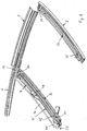
- a vehicle 1 (see FIG. 1) contains a vehicle roof 2 with a roof frame arrangement, a front roof transverse spar or cowl 3 above a Windscreen 4 and both sides each have a front movable side rail. 5 and 5 'and a roof-fixed rear side spar 6 and 6', which is approximately extends from the B-pillar 7 to the C-pillar 8.
- a roof opening 9 extends between the cowl 3 and the two movable side rails 5 and 5 ' and is bounded on the back by a rear roof cross member 10, with the rear side rails 6 and 6 'or the B-pillars 7 is firmly connected.
- a back fixed roof section 11 extends between the rear side rails 6 and 6 'and from the rear roof cross member 10 to another roof transverse spar at the end of the vehicle roof 2 above the rear window.
- a lid 12, z. B. is a glass lid, an outside sliding roof provided for closing and at least partially releasing the roof opening 9.
- the lid 12 is in the region of its front edge 13 on both sides by means of a Bearing unit slidably mounted on a respective guide means, a guide rail 14 on the front side rail 5, 5 'and another guide rail 15 at the rear side spar 6, 6 'has.
- the lid 12 is laterally by means of a bearing unit 17 at a respective Guide device slidably mounted, the guide rail 18 on rear side spar 6, 6 'has.
- To release the roof opening 9 is the Lid 12 raised by means of the bearing units 17 at its rear edge 16 and moved back over the rear fixed roof section 11 (position according to Fig. 1).
- Such a cover 12 with bearing device and drive mechanism is disclosed in DE 197 13 347 C1 and is therefore not explained here.
- Each front side rail 5, 5 ' is out of its functional or external position (see Fig. 1 and 2), in which he the A-pillar 19, 19 'and the cowl 3 with the fixed rear side spar 6, 6 'connects and the guide rail 14 for storage or Moving the lid 12 provides, in an inner position (see FIG. 10) displaceable, as soon as the lid 12 is arranged in a rear open position and without bearing engagement with the guide rail 14 (FIG. 1).
- the roof construction is substantially symmetrical with respect to the vertical vehicle longitudinal median plane, so that the description of the two movable side rails 5 and 5 'and the Bearing and drive devices mainly on the basis of the left side member. 5 takes place (the right side spar 5 'is not shown in some figures).
- the cowl 3 has a guide rail 20 which extends between the two A-pillars 19, 19 'over the entire length of the cowl 3 extends.
- the upper edge 21 of the windscreen 4 runs along a three-dimensional Curve with in particular arched forward and upward center section (In FIG. 1, however, the upper edge is shown simplified as a straight line).
- the cowl 3 as well as the attached guide rail 20 is a three-dimensional arched or curved component (see, for example, FIG. Figs. 2 and 3).
- the rear roof cross member 10 which is comparable to the cowl 3 a three-dimensional is curved member, also has a guide rail 22, the Course of the rear roof cross member 10 is adapted.
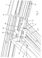
- each of the two movable front side rails 5, 5 ' is for slidably supporting each of the two movable front side rails 5, 5 'are each a front control slide 23 and 23' and a rear Control slide 24 and 24 'slidably mounted.
- At the front control slide 23, 23 ' is a gear 25, 25' rotatably mounted on one of the front Guide rail 20 formed toothing 26, z. B. attached to an attached or trained rack, is engaged.
- the rear Control slide 24 and 24 'a gear 27 and 27' rotatably mounted the a toothing 28 formed on the rear guide rail 22, z. B. on an attached or trained rack, is engaged.
- a respective universal joint device 29 connects the front control slide 23, 23 'and the rear control slides 24, 24' of the respective side member 5 or 5 'together and couples their gears 25 and 27 or 25' and 27 ' rotatable with each other.
- the universal joint 29 includes a front end piece 30, on the front control slide 23 coaxial with the axis of rotation of Gear 25 is mounted, a rear end 31, which at the rear Control slide 24 is mounted coaxially to the axis of rotation of the gear 27, and a central piece 32, which at a front hinge point 33 and a rear hinge point 34 articulated with the front and the rear end piece 30 and 31, respectively connected is.
- the side rail 5 is at the center piece 32 of the universal joint device 29 by means of a front bearing 35, a rear bearing 36 and a middle bearing 37 mounted so that it about a pivot axis 38, the through the front and rear hinge points 33 and 34 of the cardan joint device 29 extends relative to the vehicle roof or the front and the rear Control slide 23 and 24 is pivotable.
- a propeller shaft 39 of the Cardan 29, the two gears 25 and 27 with each other coupled, is accordingly formed in several parts and is in the front end 30th and rotatably mounted in the rear end piece 31.
- the front end 30 of the Cardan 29 and the propeller shaft includes a device for Length compensation (not shown), so that the effective length of Cardan 29 is changeable and at varying distances between the front guide rail 20 and the rear guide rail 22 can adjust.
- a device for Length compensation (not shown)
- the illustrated middle storage 37 with only one Articulation of the universal joint 29 can in particular in a more curved side rail 5 also several middle bearings for Connection of the universal joint 29 with the side spar 5 and Accordingly, a multiple subdivision or deflection of the propeller shaft 39 be provided so that the course of the propeller shaft 39 to the shape of the soholmes 5 can be adjusted. This is especially true for a stronger one curved side spar appropriate.
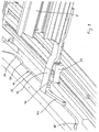
- the rear roof cross member 10 includes a between the two fixed side rails 6 and 6 'extending control link 40 (see Fig. 5) with a control track 41 and 41 'for each movable side rail 5 and 5'.
- a holding part 42 which projects beyond the rear end 43 of the side member 5 to the rear, contains an inwardly extending control arm 44, at the end of a control pin 45 is arranged.
- the control bolt 45 is assigned to this side rail 5 Control track 41 of the control link 40 slidably received and led to it.
- the respective position of the control pin 45 relative to the rear Control slide 24 and the pivot axis 38 of the side member 5 defines a Pivoting position of the side member 5 about the pivot axis 38 fixed.
- a support pin 46 is additionally arranged (Fig. 7) which is coaxial with the pivot axis 38 of the side member 5 and thus when pivoting the side member 5 not from the pivot axis 38th is moved out.
- the rear roof cross member 10 includes at its two outer ends each a U-shaped, open to the rear gate 47 of limited Length in which the support pin 46 in and near the outer position of the side spar 5 is recorded without play.
- a corresponding central backdrop 48 (FIG. 5) is mounted in the center of the rear roof transverse spar 10 and guides the support bolts 46 of the two side rails 5 and 5 'in their inner position backlash.
- the front guide rail 20 as well as the rear guide rail 22 point two guide webs 49 and 50, each directed upwards in particular on, the both sides of the teeth 26 and 28, d. H. with respect to the vehicle's longitudinal axis before or behind the teeth 26 and 28, respectively.
- the two front control slide 23 and 23 'each have one towards the vehicle center directed guide extension 51 and 51 ', z. B. as a U-shaped profile is formed and abuts the respective guide web 49 and 50 or this embraces from above.
- the guide extension 51 on the left front control slide 23 arranged so that they are on the rear guide bar 50 is mounted while the guide extension 51 'on the right front control slide 23 'arranged so that they on the front guide bar 49 is stored.
- the two rear control slides 24 and 24 ' are each with one at the rear Guide rail 22 guided pressure-resistant drive cable 53 or 53 ', such as it is known from sunroof drives connected.
- the two drive cables 53 and 53 ' are synchronously driven by a common drive motor.
- each movable side rail 5, 5 'in its outer position with respect to the vertical vehicle longitudinal center plane on outside arranged front end 54 must in the process of the side spar 5, 5 'from its external position to its inner position, in which the two Side bars 5, 5 'arranged approximately parallel to the vertical vehicle longitudinal center plane are and abut each other, the front end 54 of the side member 5 in Compared to its rear end 43 a greater way along the front Cover guide rail 20.
- the respective units of gear 25 and rack 26th or gear 27 and rack 28 on the front and the rear control slide 23 and 24 may be designed differently, so that the front control slide 23 relative to the rear control slide 24 a correspondingly larger Travel distance can cover.
- the formed two tooth pairings with different modules, so that at same rotational speed, the front gear 25 relative to the rear Gear 27 covers a greater distance.
- the lid 12 is out of his Closed position by means of a drive device along the guides 14 and 15 on the side rails 5, 5 'and 6 and 6' to the rear and over the rear Roof section 11 moved into its open position, in which its storage facility out of engagement with the guides 14 of the front side rails 5, 5 '.
- the drive device for the two side rails 5, 5 ' is activated, so that the two drive cables 53, 53 ', the two rear control slide Move 24 and 24 'inwards.
- On the left side spar 5 is doing first of Control bolt 45 in a steeply downward outer track portion 55th the control track 41 (see FIG. 5) moves down so that the control arm 44th and the holding part 42 and thus the side member 5 are pivoted.
- the control track 41 then points to the steeply inclined first, outer track portion 55 is a substantially parallel to the rear guide rail 22 extending second track section 56.
- the side rail retains 5 at its inward displacement its pivotal position substantially at.
- a small ledge 57 on the second web section 56 and a following higher lying track section 56 may have a slight return pivoting of the Side bars 5 effect.
- the control track 41 contains a rising third track section 58, which in a roof fourth Path section 59 passes, which again runs parallel to the guide rail 22.
- the right side rail 5 ' is by means of the control track 41', which corresponds substantially the control track 41 of the left side member 5 is formed in its Pivoting position corresponding to the left side rail 5 adjustable.
- the Control track 41 'of the right side member 5' is, for example, in its entirety with otherwise the same education further down and thus closer to the rear Guide rail 22 is formed.
- the pivoting mechanism is accordingly adapted to allow a similar pivoting of the right side member 5 '.
- the right side rail 5 'becomes synchronous with the left side rail 5 moves and pivots.
- the return movement of the two side rails 5 and 5 'takes place in opposite movement.
- rear side rails of the Vehicle roofs which laterally comprise a rear roof opening, made movable be. Then, contrary to the described embodiment the guide on a rear roof crossbar longer than the guide a front roof crossbar.
- a flexible rotatable rotary drive shaft can be used, which is housed in a tube is.
- the side rail is then on the pipe at one or more Attached places.
Landscapes
- Engineering & Computer Science (AREA)
- Mechanical Engineering (AREA)
- Body Structure For Vehicles (AREA)
- Power-Operated Mechanisms For Wings (AREA)
- Window Of Vehicle (AREA)
- Seal Device For Vehicle (AREA)
Abstract
Description
- Fig. 1
- in perspektivischer Draufsicht ein Personenfahrzeug mit einem Fahrzeugdach und einem Deckel, der zur Freigabe einer Dachöffnung nach hinten in eine Offenstellung bewegt ist;
- Fig. 2
- in perspektivischer Draufsicht eine Dachrahmenanordnung mit zwei bewegbaren Seitenholmen, die an zwei Dachquerbauteilen in Dachquerrichtung verschiebbar gelagert sind;
- Fig. 3
- in Seitenansicht die Dachrahmenanordnung mit dem linken bewegbaren Seitenholm;
- Fig. 4
- in perspektivischer Draufsicht in vergrößerter Darstellung das Vorderende des linken bewegbaren Seitenholms mit seiner Lagereinrichtung am Windlauf;
- Fig. 5
- in perspektivischer Draufsicht in vergrößerter Darstellung das Hinterende des linken bewegbaren Seitenholms mit seiner Lagereinrichtung am hinteren Dachquerbauteil;
- Fig. 6
- in perspektivischer Draufsicht gemäß Fig. 2 die Dachrahmenanordnung mit dem linken bewegbaren Seitenholm, der in seiner Außenstellung um seine Längsachse verschwenkt ist;
- Fig. 7
- in perspektivischer Draufsicht in vergrößerter Darstellung das Hinterende des linken bewegbaren Seitenholms mit seiner Lagereinrichtung am hinteren Dachquerbauteil in einer ersten einwärts bewegten Zwischenstellung;
- Fig. 8
- in perspektivischer Draufsicht gemäß Fig. 2 die Dachrahmenanordnung mit den beiden bewegbaren Seitenholmen in einer weiteren einwärts bewegten Zwischenstellung;
- Fig. 9
- in perspektivischer Draufsicht in vergrößerter Darstellung das Hinterende des linken bewegbaren Seitenholms mit seiner Lagereinrichtung in der Zwischenstellung gemäß Fig. 8; und
- Fig. 10
- in perspektivischer Draufsicht gemäß Fig. 2 die Dachrahmenanordnung mit den beiden bewegbaren Seitenholmen in ihrer Innen- oder Endstellung.
- 1
- Fahrzeug
- 2
- Fahrzeugdach
- 3
- Windlauf
- 4
- Frontscheibe
- 5
- bewegbarer Seitenholm
- 6
- hinterer Seitenholm
- 7
- B-Säule
- 8
- C-Säule
- 9
- Dachöffnung
- 10
- hinterer Dachquerholm
- 11
- fester Dachabschnitt
- 12
- Deckel
- 13
- Vorderrand
- 14
- Führungsschiene
- 15
- Führungsschiene
- 16
- Hinterrand
- 17
- Lagereinheit
- 18
- Führungsschiene
- 19
- A-Säule
- 20
- vordere Führungsschiene
- 21
- Oberrand
- 22
- hintere Führungsschiene
- 23
- vorderer Steuerschlitten
- 24
- hinterer Steuerschlitten
- 25
- Zahnrad
- 26
- Zahnstange
- 27
- Zahnrad
- 28
- Zahnstange
- 29
- Kardangelenkeinrichtung
- 30
- vorderes Endstück
- 31
- hinteres Endstück
- 32
- Mittelstück
- 33
- vordere Gelenkstelle
- 34
- hintere Gelenkstelle
- 35
- vordere Lagerung
- 36
- hintere Lagerung
- 37
- mittlere Lagerung
- 38
- Schwenkachse
- 39
- Kardanwelle
- 40
- Steuerkulisse
- 41
- Steuerbahn
- 42
- Halteteil
- 43
- Hinterende
- 44
- Steuerarm
- 45
- Steuerbolzen
- 46
- Abstützbolzen
- 47
- äußere Kulisse
- 48
- mittlere Kulisse
- 49
- Führungssteg
- 50
- Führungssteg
- 51
- Führungsverlängerung
- 52
- Führungsverlängerung
- 53
- Antriebskabel
- 54
- Vorderende
- 55
- erster äußerer Bahnabschnitt
- 56
- zweiter Bahnabschnitt
- 57
- Absatz
- 58
- dritter Bahnabschnitt
- 59
- vierter Bahnabschnitt
Claims (22)
- Fahrzeugdach mit einer Dachöffnung und einer bewegbaren Dachschließeinrichtung zum Verschließen oder zumindest teilweisen Freigeben der Dachöffnung, die zwischen zwei Seitenholmen des Fahrzeugdaches angeordnet ist,
dadurch gekennzeichnet, daß die zwei Seitenholme (5, 5') am Fahrzeugdach (2) in Querrichtung bewegbar gelagert sind und bei freigelegter Dachöffnung (9) zwischen ihrer Außenstellung und einer gegenseitig angenäherten Innenstellung verstellbar sind. - Fahrzeugdach nach Anspruch 1,
dadurch gekennzeichnet, daß jeder Seitenholm (5, 5') eine Führungseinrichtung (14) für die bewegbare Dachschließeinrichtung (12) aufweist. - Fahrzeugdach nach Anspruch 1 oder 2,
dadurch gekennzeichnet, daß jeder Seitenholm (5, 5') im Bereich seines Vorderendes (54) an einem vorderen Dachquerbauteil (3) und im Bereich seines Hinterendes (43) an einem hinteren Dachquerbauteil (10) bewegbar gelagert ist. - Fahrzeugdach nach Anspruch 3,
dadurch gekennzeichnet, daß der vordere Bewegungsweg und der hintere Bewegungsweg jedes Seitenholms (5, 5') entlang dem vorderen Dachquerbauteil (3) bzw. dem hinteren Dachquerbauteil (10) bei der Verstellung des Seitenholms (5, 5') zwischen der Außenstellung und der Innenstellung unterschiedliche Längen aufweisen. - Fahrzeugdach nach Anspruch 3 oder 4,
dadurch gekennzeichnet, daß jeder Seitenholm (5, 5') mittels einer vorderen und einer hinteren Lager- und Führungseinheit (23 bzw. 24) an einer vorderen und einer hinteren Führung (20 bzw. 22) des vorderen bzw. hinteren Dachquerbauteils (3 bzw. 10) verschiebbar gelagert ist. - Fahrzeugdach nach Anspruch 5,
dadurch gekennzeichnet, daß jeder Seitenholm (5, 5') an den beiden Lager- und Führungseinheiten (23, 24) um eine Längsachse (38) schwenkbar gelagert ist. - Fahrzeugdach nach einem der Ansprüche 1 bis 6,
dadurch gekennzeichnet, daß jeder Seitenholm (5, 5') eine vordere und eine hintere Antriebseinheit (25 bzw. 27) aufweist, die an den Führungen des vorderen bzw. hinteren Dachquerbauteils (3 bzw. 10) in Antriebseingriff sind. - Fahrzeugdach nach Anspruch 7,
dadurch gekennzeichnet, daß die vordere Antriebseinheit (25) gegenüber der hinteren Antriebseinheit (27) bei gleichzeitigem Antrieb einen größeren oder einen kleineren Antriebsweg zurücklegt. - Fahrzeugdach nach Anspruch 7 oder 8,
dadurch gekennzeichnet, daß die vordere Antriebseinheit (25) und die hintere Antriebseinheit (27) miteinander insbesondere mechanisch gekoppelt sind. - Fahrzeugdach nach einem der Ansprüche 7 bis 9,
dadurch gekennzeichnet, daß die vordere Antriebseinheit und die hintere Antriebseinheit jeweils ein Drehantriebselement (25 bzw. 27) aufweisen, das in Form- oder Reibeingriff mit den Führungen (20 bzw. 22) oder mit Eingriffsbahnen (26 bzw. 28) der Führungen (20 bzw. 22) ist. - Fahrzeugdach nach einem der Ansprüche 7 bis 10,
dadurch gekennzeichnet, daß die vordere Antriebseinheit und die hintere Antriebseinheit jeweils ein Antriebsrad (25 bzw. 27) aufweisen, die beiden Antriebsräder (25 und 27)unterschiedliche Wirkdurchmesser aufweisen, miteinander rotatorisch gekoppelt sind und unterschiedliche Wegstrecken zurücklegen. - Fahrzeugdach nach einem der Ansprüche 7 bis 11,
dadurch gekennzeichnet, daß die vordere Antriebseinheit und die hintere Antriebseinheit bzw. die Antriebsräder (25, 27) mittels einer Welle, insbesondere einer Kardanwelle (29, 39), miteinander verbunden sind. - Fahrzeugdach nach Anspruch 11 oder 12,
dadurch gekennzeichnet, daß die Antriebsräder Zahnräder (25, 27) sind und die Verzahnungen der vorderen Antriebseinheit und der hinteren Antriebseinheit sich in ihrem jeweiligen Modul unterscheiden. - Fahrzeugdach nach einem der Ansprüche 1 bis 13,
dadurch gekennzeichnet, daß jeder Seitenholm (5, 5') mittels einer Schwenkeinrichtung in seiner Schwenkstellung um eine Längsachse (38) verstellbar ist. - Fahrzeugdach nach Anspruch 14,
dadurch gekennzeichnet, daß die Schwenkeinrichtung eine Steuerbahn (41) mit mehreren Bahnabschnitten (55, 56, 58, 59) aufweist, an der ein Steuerteil (45) des Seitenholms (5, 5') in Eingriff ist. - Fahrzeugdach nach Anspruch 15,
dadurch gekennzeichnet, daß eine die Steuerbahn (41) enthaltende Steuerkulisse (40) entlang der vorderen oder der hinteren Führungsschiene (22 bzw. 22) angeordnet ist. - Fahrzeugdach nach Anspruch 15 oder 16,
dadurch gekennzeichnet, daß ein Steuerarm (42) des Seitenholms (5) an der Steuerbahn (41) in Eingriff ist und den jeweiligen Bahnabschnitten (55, 56, 58, 59) der Steuerbahn (41) entsprechende Schwenkstellungen einnimmt. - Fahrzeugdach nach einem der Ansprüche 15 bis 17,
dadurch gekennzeichnet, daß ein erster äußerer Bahnabschnitt (56), der gegenüber der Verschieberichtung des Seitenholms (5) abwärts geneigt ist, eine anfängliche Einwärtsverschwenkung des Seitenholms (5) steuert. - Fahrzeugdach nach einem der Ansprüche 1 bis 18,
dadurch gekennzeichnet, daß zumindest eine Führungskulisse (45, 48) am Verschiebeweg des Seitenholms (5, 5') angeordnet ist und ein Halteteil (46) des Seitenholms (5, 5') aufnimmt. - Fahrzeugdach nach Anspruch 19,
dadurch gekennzeichnet, daß das Halteteil (46) ein am Steuerarm (42) des Seitenholms (5, 5') angeordneter Abstützbolzen (46) ist, der koaxial zur Schwenkachse (38) des Seitenholms (5, 5') angeordnet ist. - Fahrzeugdach nach Anspruch 19 oder 20,
dadurch gekennzeichnet, daß jeweils eine äußere Führungskulisse (45) in Zuordnung zur Außenstellung des Seitenholms (5, 5') und eine innere Führungskulisse (48) in Zuordnung zur Innenstellung des Seitenholms (5, 5') vorgesehen ist. - Fahrzeugdach nach einem der Ansprüche 1 bis 21,
dadurch gekennzeichnet, daß ein Deckel (12), insbesondere ein Glasdeckel, die vordere Deckeleinrichtung bildet und in einer Öffnungsstellung, in der zumindest sein Hinterrand (16) angehoben ist, nach hinten über das Fahrzeugdach (11) verfahrbar ist.
Applications Claiming Priority (2)
| Application Number | Priority Date | Filing Date | Title |
|---|---|---|---|
| DE10331143 | 2003-07-09 | ||
| DE10331143A DE10331143B8 (de) | 2003-07-09 | 2003-07-09 | Fahrzeugdach mit einer Dachöffnung und einer bewegbaren Dachschließeinrichtung |
Publications (3)
| Publication Number | Publication Date |
|---|---|
| EP1495890A2 true EP1495890A2 (de) | 2005-01-12 |
| EP1495890A3 EP1495890A3 (de) | 2007-01-03 |
| EP1495890B1 EP1495890B1 (de) | 2009-09-16 |
Family
ID=33441693
Family Applications (1)
| Application Number | Title | Priority Date | Filing Date |
|---|---|---|---|
| EP04015870A Expired - Lifetime EP1495890B1 (de) | 2003-07-09 | 2004-07-06 | Fahrzeugdach mit einer Dachöffnung und einer bewegbaren Dachschliesseinrichtung |
Country Status (4)
| Country | Link |
|---|---|
| US (1) | US20050046242A1 (de) |
| EP (1) | EP1495890B1 (de) |
| AT (1) | ATE442971T1 (de) |
| DE (2) | DE10331143B8 (de) |
Cited By (1)
| Publication number | Priority date | Publication date | Assignee | Title |
|---|---|---|---|---|
| WO2017067667A1 (de) * | 2015-10-23 | 2017-04-27 | Daimler Ag | Schiebe-und/oder hebedach für einen kraftwagen, insbesondere einen personenkraftwagen |
Families Citing this family (3)
| Publication number | Priority date | Publication date | Assignee | Title |
|---|---|---|---|---|
| DE202004017220U1 (de) * | 2004-11-08 | 2006-03-23 | Inalfa Roof Systems Group B.V. | Fahrzeug |
| DE102011007004B8 (de) * | 2011-04-07 | 2013-01-10 | Bos Gmbh & Co. Kg | Rollobaueinheit für ein Kraftfahrzeug |
| DE102011081348A1 (de) | 2011-08-22 | 2013-02-28 | Bos Gmbh & Co. Kg | Dachfenstereinheit und Fahrzeug mit einer Dachfenstereinheit |
Family Cites Families (11)
| Publication number | Priority date | Publication date | Assignee | Title |
|---|---|---|---|---|
| US5078447A (en) * | 1990-01-12 | 1992-01-07 | C&C Incorporated | Multi-position retractable vehicle roof |
| US5558388A (en) * | 1992-02-05 | 1996-09-24 | Webasto Karosseriesysteme Gmbh | Vehicle roof |
| DE19634507C1 (de) * | 1996-08-27 | 1998-01-22 | Daimler Benz Ag | In einem Fahrzeugheck der Karosserie eines Personenkraftwagens versenkbares Fahrzeugdach |
| EP0863817B1 (de) * | 1996-10-01 | 2003-07-30 | WEBASTO KAROSSERIESYSTEME GmbH | Fahrzeugdach mit wenigstens einem deckel |
| DE19713347C5 (de) * | 1997-03-29 | 2005-12-22 | Webasto Ag | Fahrzeugdach mit wenigstens einem oberhalb des festen Fahrzeugdachs verschiebbaren Deckel |
| DE19927234C1 (de) * | 1999-06-15 | 2000-07-27 | Webasto Vehicle Sys Int Gmbh | Führungsschiene |
| DE10001941C1 (de) * | 2000-01-18 | 2001-05-10 | Webasto Vehicle Sys Int Gmbh | Fahrzeugdachstruktur mit in einen Stauraum überführbaren Seitenholmen |
| DE10023864B4 (de) * | 2000-05-16 | 2005-06-23 | Webasto Ag | Klappverdeck eines Fahrzeugs |
| DE10043703B4 (de) * | 2000-09-04 | 2009-07-30 | Webasto Ag | Absenkbares Fahrzeugdach |
| DE10202097B4 (de) * | 2002-01-21 | 2004-07-22 | Webasto Vehicle Systems International Gmbh | Umwandelbares Dach eines Fahrzeugs |
| DE10203877B4 (de) * | 2002-01-31 | 2005-01-20 | Webasto Vehicle Systems International Gmbh | Fahrzeugdach mit seitwärts öffnenden Dachelementen |
-
2003
- 2003-07-09 DE DE10331143A patent/DE10331143B8/de not_active Expired - Fee Related
-
2004
- 2004-07-06 DE DE502004010060T patent/DE502004010060D1/de not_active Expired - Lifetime
- 2004-07-06 EP EP04015870A patent/EP1495890B1/de not_active Expired - Lifetime
- 2004-07-06 AT AT04015870T patent/ATE442971T1/de not_active IP Right Cessation
- 2004-07-08 US US10/885,963 patent/US20050046242A1/en not_active Abandoned
Cited By (1)
| Publication number | Priority date | Publication date | Assignee | Title |
|---|---|---|---|---|
| WO2017067667A1 (de) * | 2015-10-23 | 2017-04-27 | Daimler Ag | Schiebe-und/oder hebedach für einen kraftwagen, insbesondere einen personenkraftwagen |
Also Published As
| Publication number | Publication date |
|---|---|
| ATE442971T1 (de) | 2009-10-15 |
| DE502004010060D1 (de) | 2009-10-29 |
| US20050046242A1 (en) | 2005-03-03 |
| DE10331143B4 (de) | 2006-08-24 |
| EP1495890B1 (de) | 2009-09-16 |
| DE10331143A1 (de) | 2005-02-10 |
| DE10331143B8 (de) | 2007-03-08 |
| EP1495890A3 (de) | 2007-01-03 |
Similar Documents
| Publication | Publication Date | Title |
|---|---|---|
| EP1074415B1 (de) | Cabriolet-Fahrzeug | |
| EP0395847B1 (de) | Antriebseinrichtung für ein motorisch angetriebenes Klappverdeck | |
| DE102005007031B4 (de) | Fahrzeugdach mit einem oberhalb des Daches verschiebbaren Dachteil | |
| EP2451665B2 (de) | Schiebedachvorrichtung insbesondere für ein kraftfahrzeug | |
| DE10200221A1 (de) | Cabrioletverdeck für ein Kraftfahrzeug | |
| EP3009283B1 (de) | Antriebssystem für ein bewegliches dachteil eines kraftfahrzeug-dachmoduls | |
| EP1562768B1 (de) | Verdeck für ein cabriolet-fahrzeug | |
| EP1080965B1 (de) | Antriebsvorrichtung für ein Schwenkbauteil | |
| EP1129880A2 (de) | Öffnungsfähiges Fahrzeugdach | |
| DE19632427A1 (de) | Schwenkschiebetür für Fahrzeuge | |
| DE2918002A1 (de) | Schwenkschiebetuer fuer fahrzeuge, insbesondere kraftfahrzeuge | |
| EP1254799A2 (de) | Öffnungsfähiges Fahrzeugdach | |
| DE10326981B4 (de) | Fahrzeug, das von einem Pick-up in ein Cabrio umwandelbar ist | |
| DE10203204B4 (de) | Verstellvorrichtung für ein Faltdach eines Fahrzeugs | |
| DE19634324C2 (de) | Fahrzeugdach | |
| DE2507893B2 (de) | Fensterheber für vertikal unterteilte Kraftfahrzeugschiebefenster | |
| DE60009784T2 (de) | Konstruktion eines öffnungsfähigen Fahrzeugdaches | |
| EP1495890B1 (de) | Fahrzeugdach mit einer Dachöffnung und einer bewegbaren Dachschliesseinrichtung | |
| DE102021131573A1 (de) | Fahrzeugdachsystem mit einer Dachöffnung | |
| EP1676735B1 (de) | Seitenfensterrollosystem für ein Dreiecksfenster eines Kraftfahrzeugs | |
| DE202007001217U1 (de) | Fahrzeugdach mit einem oberhalb des Daches verschiebbaren Dachteil | |
| DE10331144B4 (de) | Fahrzeugdach mit einem bewegbar gelagerten und verriegelbaren Dachbauteil | |
| DE3878644T2 (de) | Schiebedach fuer ein kraftfahrzeug. | |
| EP1813457B1 (de) | Dachkinematik für ein zu öffnendes Fahrzeugdach | |
| DE19624706B4 (de) | Schwenkschiebetür für ein Fahrzeug |
Legal Events
| Date | Code | Title | Description |
|---|---|---|---|
| PUAI | Public reference made under article 153(3) epc to a published international application that has entered the european phase |
Free format text: ORIGINAL CODE: 0009012 |
|
| AK | Designated contracting states |
Kind code of ref document: A2 Designated state(s): AT BE BG CH CY CZ DE DK EE ES FI FR GB GR HU IE IT LI LU MC NL PL PT RO SE SI SK TR |
|
| AX | Request for extension of the european patent |
Extension state: AL HR LT LV MK |
|
| PUAL | Search report despatched |
Free format text: ORIGINAL CODE: 0009013 |
|
| AK | Designated contracting states |
Kind code of ref document: A3 Designated state(s): AT BE BG CH CY CZ DE DK EE ES FI FR GB GR HU IE IT LI LU MC NL PL PT RO SE SI SK TR |
|
| AX | Request for extension of the european patent |
Extension state: AL HR LT LV MK |
|
| 17P | Request for examination filed |
Effective date: 20070627 |
|
| AKX | Designation fees paid |
Designated state(s): AT BE BG CH CY CZ DE DK EE ES FI FR GB GR HU IE IT LI LU MC NL PL PT RO SE SI SK TR |
|
| 17Q | First examination report despatched |
Effective date: 20071213 |
|
| GRAP | Despatch of communication of intention to grant a patent |
Free format text: ORIGINAL CODE: EPIDOSNIGR1 |
|
| GRAS | Grant fee paid |
Free format text: ORIGINAL CODE: EPIDOSNIGR3 |
|
| GRAA | (expected) grant |
Free format text: ORIGINAL CODE: 0009210 |
|
| AK | Designated contracting states |
Kind code of ref document: B1 Designated state(s): AT BE BG CH CY CZ DE DK EE ES FI FR GB GR HU IE IT LI LU MC NL PL PT RO SE SI SK TR |
|
| REG | Reference to a national code |
Ref country code: GB Ref legal event code: FG4D Free format text: NOT ENGLISH |
|
| REG | Reference to a national code |
Ref country code: CH Ref legal event code: EP |
|
| REG | Reference to a national code |
Ref country code: IE Ref legal event code: FG4D |
|
| REF | Corresponds to: |
Ref document number: 502004010060 Country of ref document: DE Date of ref document: 20091029 Kind code of ref document: P |
|
| PG25 | Lapsed in a contracting state [announced via postgrant information from national office to epo] |
Ref country code: SE Free format text: LAPSE BECAUSE OF FAILURE TO SUBMIT A TRANSLATION OF THE DESCRIPTION OR TO PAY THE FEE WITHIN THE PRESCRIBED TIME-LIMIT Effective date: 20090916 Ref country code: FI Free format text: LAPSE BECAUSE OF FAILURE TO SUBMIT A TRANSLATION OF THE DESCRIPTION OR TO PAY THE FEE WITHIN THE PRESCRIBED TIME-LIMIT Effective date: 20090916 |
|
| PG25 | Lapsed in a contracting state [announced via postgrant information from national office to epo] |
Ref country code: NL Free format text: LAPSE BECAUSE OF FAILURE TO SUBMIT A TRANSLATION OF THE DESCRIPTION OR TO PAY THE FEE WITHIN THE PRESCRIBED TIME-LIMIT Effective date: 20090916 Ref country code: SI Free format text: LAPSE BECAUSE OF FAILURE TO SUBMIT A TRANSLATION OF THE DESCRIPTION OR TO PAY THE FEE WITHIN THE PRESCRIBED TIME-LIMIT Effective date: 20090916 Ref country code: PL Free format text: LAPSE BECAUSE OF FAILURE TO SUBMIT A TRANSLATION OF THE DESCRIPTION OR TO PAY THE FEE WITHIN THE PRESCRIBED TIME-LIMIT Effective date: 20090916 |
|
| NLV1 | Nl: lapsed or annulled due to failure to fulfill the requirements of art. 29p and 29m of the patents act | ||
| PG25 | Lapsed in a contracting state [announced via postgrant information from national office to epo] |
Ref country code: CY Free format text: LAPSE BECAUSE OF FAILURE TO SUBMIT A TRANSLATION OF THE DESCRIPTION OR TO PAY THE FEE WITHIN THE PRESCRIBED TIME-LIMIT Effective date: 20090916 |
|
| REG | Reference to a national code |
Ref country code: IE Ref legal event code: FD4D |
|
| PG25 | Lapsed in a contracting state [announced via postgrant information from national office to epo] |
Ref country code: PT Free format text: LAPSE BECAUSE OF FAILURE TO SUBMIT A TRANSLATION OF THE DESCRIPTION OR TO PAY THE FEE WITHIN THE PRESCRIBED TIME-LIMIT Effective date: 20100118 Ref country code: CZ Free format text: LAPSE BECAUSE OF FAILURE TO SUBMIT A TRANSLATION OF THE DESCRIPTION OR TO PAY THE FEE WITHIN THE PRESCRIBED TIME-LIMIT Effective date: 20090916 Ref country code: IE Free format text: LAPSE BECAUSE OF FAILURE TO SUBMIT A TRANSLATION OF THE DESCRIPTION OR TO PAY THE FEE WITHIN THE PRESCRIBED TIME-LIMIT Effective date: 20090916 Ref country code: EE Free format text: LAPSE BECAUSE OF FAILURE TO SUBMIT A TRANSLATION OF THE DESCRIPTION OR TO PAY THE FEE WITHIN THE PRESCRIBED TIME-LIMIT Effective date: 20090916 Ref country code: ES Free format text: LAPSE BECAUSE OF FAILURE TO SUBMIT A TRANSLATION OF THE DESCRIPTION OR TO PAY THE FEE WITHIN THE PRESCRIBED TIME-LIMIT Effective date: 20091227 Ref country code: RO Free format text: LAPSE BECAUSE OF FAILURE TO SUBMIT A TRANSLATION OF THE DESCRIPTION OR TO PAY THE FEE WITHIN THE PRESCRIBED TIME-LIMIT Effective date: 20090916 |
|
| PG25 | Lapsed in a contracting state [announced via postgrant information from national office to epo] |
Ref country code: SK Free format text: LAPSE BECAUSE OF FAILURE TO SUBMIT A TRANSLATION OF THE DESCRIPTION OR TO PAY THE FEE WITHIN THE PRESCRIBED TIME-LIMIT Effective date: 20090916 |
|
| PLBE | No opposition filed within time limit |
Free format text: ORIGINAL CODE: 0009261 |
|
| STAA | Information on the status of an ep patent application or granted ep patent |
Free format text: STATUS: NO OPPOSITION FILED WITHIN TIME LIMIT |
|
| PG25 | Lapsed in a contracting state [announced via postgrant information from national office to epo] |
Ref country code: DK Free format text: LAPSE BECAUSE OF FAILURE TO SUBMIT A TRANSLATION OF THE DESCRIPTION OR TO PAY THE FEE WITHIN THE PRESCRIBED TIME-LIMIT Effective date: 20090916 |
|
| 26N | No opposition filed |
Effective date: 20100617 |
|
| PG25 | Lapsed in a contracting state [announced via postgrant information from national office to epo] |
Ref country code: GR Free format text: LAPSE BECAUSE OF FAILURE TO SUBMIT A TRANSLATION OF THE DESCRIPTION OR TO PAY THE FEE WITHIN THE PRESCRIBED TIME-LIMIT Effective date: 20091217 |
|
| BERE | Be: lapsed |
Owner name: WEBASTO A.G. Effective date: 20100731 |
|
| PG25 | Lapsed in a contracting state [announced via postgrant information from national office to epo] |
Ref country code: MC Free format text: LAPSE BECAUSE OF NON-PAYMENT OF DUE FEES Effective date: 20100731 |
|
| REG | Reference to a national code |
Ref country code: CH Ref legal event code: PL |
|
| GBPC | Gb: european patent ceased through non-payment of renewal fee |
Effective date: 20100706 |
|
| PG25 | Lapsed in a contracting state [announced via postgrant information from national office to epo] |
Ref country code: LI Free format text: LAPSE BECAUSE OF NON-PAYMENT OF DUE FEES Effective date: 20100731 Ref country code: CH Free format text: LAPSE BECAUSE OF NON-PAYMENT OF DUE FEES Effective date: 20100731 |
|
| PG25 | Lapsed in a contracting state [announced via postgrant information from national office to epo] |
Ref country code: BE Free format text: LAPSE BECAUSE OF NON-PAYMENT OF DUE FEES Effective date: 20100731 |
|
| PG25 | Lapsed in a contracting state [announced via postgrant information from national office to epo] |
Ref country code: GB Free format text: LAPSE BECAUSE OF NON-PAYMENT OF DUE FEES Effective date: 20100706 |
|
| PG25 | Lapsed in a contracting state [announced via postgrant information from national office to epo] |
Ref country code: AT Free format text: LAPSE BECAUSE OF NON-PAYMENT OF DUE FEES Effective date: 20100706 |
|
| PG25 | Lapsed in a contracting state [announced via postgrant information from national office to epo] |
Ref country code: HU Free format text: LAPSE BECAUSE OF FAILURE TO SUBMIT A TRANSLATION OF THE DESCRIPTION OR TO PAY THE FEE WITHIN THE PRESCRIBED TIME-LIMIT Effective date: 20100317 Ref country code: LU Free format text: LAPSE BECAUSE OF NON-PAYMENT OF DUE FEES Effective date: 20100706 Ref country code: BG Free format text: LAPSE BECAUSE OF FAILURE TO SUBMIT A TRANSLATION OF THE DESCRIPTION OR TO PAY THE FEE WITHIN THE PRESCRIBED TIME-LIMIT Effective date: 20090916 |
|
| PG25 | Lapsed in a contracting state [announced via postgrant information from national office to epo] |
Ref country code: TR Free format text: LAPSE BECAUSE OF FAILURE TO SUBMIT A TRANSLATION OF THE DESCRIPTION OR TO PAY THE FEE WITHIN THE PRESCRIBED TIME-LIMIT Effective date: 20090916 |
|
| REG | Reference to a national code |
Ref country code: FR Ref legal event code: PLFP Year of fee payment: 12 |
|
| PGFP | Annual fee paid to national office [announced via postgrant information from national office to epo] |
Ref country code: DE Payment date: 20150722 Year of fee payment: 12 |
|
| PGFP | Annual fee paid to national office [announced via postgrant information from national office to epo] |
Ref country code: FR Payment date: 20150730 Year of fee payment: 12 |
|
| PGFP | Annual fee paid to national office [announced via postgrant information from national office to epo] |
Ref country code: IT Payment date: 20150728 Year of fee payment: 12 |
|
| REG | Reference to a national code |
Ref country code: DE Ref legal event code: R119 Ref document number: 502004010060 Country of ref document: DE |
|
| PG25 | Lapsed in a contracting state [announced via postgrant information from national office to epo] |
Ref country code: DE Free format text: LAPSE BECAUSE OF NON-PAYMENT OF DUE FEES Effective date: 20170201 Ref country code: FR Free format text: LAPSE BECAUSE OF NON-PAYMENT OF DUE FEES Effective date: 20160801 |
|
| REG | Reference to a national code |
Ref country code: FR Ref legal event code: ST Effective date: 20170331 |
|
| PG25 | Lapsed in a contracting state [announced via postgrant information from national office to epo] |
Ref country code: IT Free format text: LAPSE BECAUSE OF NON-PAYMENT OF DUE FEES Effective date: 20160706 |