EP1495553B1 - Appareil et procédé pour detecter un signal radio transmis - Google Patents
Appareil et procédé pour detecter un signal radio transmis Download PDFInfo
- Publication number
- EP1495553B1 EP1495553B1 EP04715536A EP04715536A EP1495553B1 EP 1495553 B1 EP1495553 B1 EP 1495553B1 EP 04715536 A EP04715536 A EP 04715536A EP 04715536 A EP04715536 A EP 04715536A EP 1495553 B1 EP1495553 B1 EP 1495553B1
- Authority
- EP
- European Patent Office
- Prior art keywords
- signal
- output
- ultra
- low
- block
- Prior art date
- Legal status (The legal status is an assumption and is not a legal conclusion. Google has not performed a legal analysis and makes no representation as to the accuracy of the status listed.)
- Expired - Fee Related
Links
Images


Classifications
-
- H—ELECTRICITY
- H04—ELECTRIC COMMUNICATION TECHNIQUE
- H04B—TRANSMISSION
- H04B1/00—Details of transmission systems, not covered by a single one of groups H04B3/00 - H04B13/00; Details of transmission systems not characterised by the medium used for transmission
- H04B1/69—Spread spectrum techniques
- H04B1/7163—Spread spectrum techniques using impulse radio
- H04B1/719—Interference-related aspects
-
- H—ELECTRICITY
- H04—ELECTRIC COMMUNICATION TECHNIQUE
- H04B—TRANSMISSION
- H04B1/00—Details of transmission systems, not covered by a single one of groups H04B3/00 - H04B13/00; Details of transmission systems not characterised by the medium used for transmission
- H04B1/69—Spread spectrum techniques
- H04B1/7163—Spread spectrum techniques using impulse radio
- H04B1/71637—Receiver aspects
Definitions
- the present invention relates generally to the field of wireless radio communications, and more specifically to rake receivers for ultra wide bandwidth radio systems.
- Ultra wide bandwidth is a form of spread-spectrum radio communication.
- the bandwidth is much wider than the bandwidth of the underlying payload or data signal.
- a UWB signal consists of a sequence of very short pulses spread over a very wide frequency range. Therefore, the terms "UWB” and "impulse radio” are often used synonymously.
- the spreading waveform is a pattern of short pulses that is modulated to encode the data.
- Figure 1 shows a rake receiver 100 according to the prior art.
- the rake receiver includes a front end 101 for pre-processing a radio signal 102.
- the rake receiver has a modular structure wherein the received radio signal 102 is processed in parallel through multiple rake fingers 110.
- Each rake finger 110 processes the signal that is received through one of the paths of propagation in a multi-path radio channel.
- each finger includes an adjustable delay block 111 controlled by a delay controller 120, and an adjustable weight block 114 controlled by a weight controller 140 for signal gain.
- the delayed received signal is multiplied 112 by a de-spreading waveform output from a de-spreading waveform generator 130, low-pass filtered 113, before the signals are scaled or weighted 114.
- Each finger extracts the corresponding path signal by "de-spreading" the received signal through the multiplication 112 by a replica of the spreading waveform that was used in the transmitter.
- the outputs of the fingers 110 are then combined in a summing block 150 before post-processing (PP) 160.
- the summing can be an algebraic sum.
- processing is usually performed on a complex representation of the received signal 102, whereby each signal corresponds to a complex waveform consisting of a real and imaginarypart, also known as in-phase and quadraturecomponents.
- the weight of each rake finger 110 is set to match the complex conjugate of the complex amplitude of the corresponding path.
- One problem with a conventional rake receiver is that the adjustable delay blocks 111 are difficult to implement for a UWB signal.
- UWB systems Due to the ultra wide bandwidth, UWB systems have a very fine temporal resolution, and are thus capable of resolvingmulti-path components that are spaced at an inverse of the bandwidth. This is usually seen as a big advantage of UWB. Multi-path resolution of components reduces signal fading because the multi-path components are different diversity paths. The probability that the components are simultaneously all in a deep fade is very low.
- the fine time resolution also means that many of the multi-path components (MPC) have to be "collected" by the rake receiver 100 in order obtain all of the available energy.
- MPC multi-path components
- a channel with N p resolvable components requires N p fingers to collect all of the available energy.
- the number of MPC increases linearly with the bandwidth. For example, a UWB system with a 10 GHz bandwidth, operating in an environment with 100 ns maximum excess delay requires 1000 fingers. Even a sparse environment, such as specified by the IEEE 802.15.3a standard channel model, requires up to 80 fingers to collect 80% of the available energy.
- DS-SS direct-sequence-spread spectrum
- A/D analog-to-digital
- UWB The goal of UWB is to enable low cost and ultra high data rate applications. To make UWB feasible for these types of applications an improved rake receiver that overcomes the above problems is desired.
- the invention provides a rake receiver for ultra wide bandwidth (UWB) communications systems. After processing a received UWB radio signal in a front-end, the UWB signal is passed in parallel through multiple rake fingers.
- UWB ultra wide bandwidth
- the number of fingers is based on the number of "significant" paths in a transmission channel, as well as cost considerations.
- Each finger includes a programmable pulse generator, a multiplier, a low-pass filter, and an adjustable weight serially connected, perhaps in an arbitrary order.
- the programmable pulse generator generates a pulse waveform with a delay corresponding to a delay of a particular path in the multi-path channel.
- the pulse waveform is multiplied with the received signal in the analog domain, and sampled and A/D converted at the symbol rate.
- the output signal is then low-pass filtered and gain controlled with an adjusted weight. Finally, the outputs from all of the fingers are combined by summation to recover the transmitted signal.
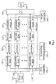
- FIG. 2 shows a rake receiver 200 for an ultra wide bandwidth communications system according to the invention.
- the receiver 200 includes a front end 101 for pre-processing a received radio signal 102.
- the front end converts the received signal 102 to an electrical signal 103 that is a complex signal including an in-phase component and a quadrature component.
- the electrical signal 103 is in digital form.
- the received radio signal 102 is a real, baseband radio signal and is converted to real, electrical baseband signal.
- the rake receiver 200 has a modular structure wherein the received radio signal 102 is processed in parallel through multiple channels known as "rake fingers" 210. Each rake finger 210 processes the signal that is received through one of the paths of propagation in a multi-path radio channel.
- each finger includes a programmable pulse generator 211 controlled by a pulse sequence controller 220.
- a multiplier 212 takes as input the electrical signal 103 and the output of the programmable pulse generator 211.
- the output of the multiplier 212 is low-pass filtered 213.
- the low-pass filter generates an output proportional to a time integral of an input to the filter.
- the filter can be an integrate-and-dump filter.
- the signal is weighted 214 according to a weight controller 240 for signal gain to compensate for attenuation in the multi-path cannel.
- the outputs of the fingers 210 are then combined in a summing block 250 before post-processing (PP) 160.
- This method of weighting and combining multiple signals is known as "maximal-ratio" combining.
- Alternative methods for the choice of the finger weights include “equal gain” weight assignment, and "optimum" weight generation.
- the difference between the rake receiver 200 according to the invention and the prior art rake receiver 100 is that the adjustable delay blocks 211 and the delay controller 120 have been eliminated, and the single de-spreading waveform generator 130 has been replaced by a plurality of programmable pulse generators 220, one for each rake finger 210.
- All of the programmable pulse generators 211 produce a pulse pattern 221.
- the pulse pattern is identical to a pulse pattern that is used in the transmitter to module data to be transmitted. However, the timings of the pulse patterns from the different pulse generators 211 are different.
- the pulse sequence controller 220 adjusts the timing of each pulse generator to match the delay of one path in the multi-path channel.
- the rake receiver 200 exploits the sparsity of the channel.
- the number of "significant" paths in the IEEE802.15.3a channel models i.e., those channels that capture 85% of the energy, lies between 40 for the UWB indoor channel model 1 (CM1), and 160 for the UWB indoor channel model 4 (CM4 ).
- CM1 UWB indoor channel model 1
- CM4 UWB indoor channel model 4
- the most significant paths are identified.
- the number of fingers 210 is then reduced to match the number of the significant paths. Trading off performance for cost can use fewer fingers.
- the pulse sequence controller 220 adjusts the timing out of each pulse generator 211 to match the delay of each significant path in the channel.
- the performance of the modified rake receiver of Figure 2 is close to that of the prior-art rake receiver, as long as the symbol rate of the payload signal is small compared to the delay spread of the channel.
- Figure 3 shows an alternative receiver 300 for situations where this symbol rate condition is not met.
- the performance for the receiver 300 is the same as for the prior-art rake receiver 100.
- the adjustable delay blocks that were removed from the receiver 200, are re-introduced as adjustable delay blocks 216 in each rake finger 310.
- the delay block 216 is arranged as the last functional block in the finger 310. This makes the delays much easier to implement because the signal bandwidth at this point is much narrower than before the low-pass filter 213.
- the blocks 216 are shown with a dashed outline to indicate that they are optional.
- Each finger 310 also includes a sample-and-holdblock 318. Again, the dashed outline indicates that the blocks 318 are also optional. These blocks make it easier to implement the adjustable weight blocks 214 and the adjustable delay blocks 216 that follow in the finger. This is especially true when the sample-and-hold blocks 218 are implemented as A/D converters, so that all functions that follow can be implemented digitally.
- the adjustable weight and delay blocks are controlled by a weight and delay controller 340.
- the sampling is at the symbol rate.
- the adjustable delay blocks 316 only need coarse adjustment, while fine timing adjustments are performed by a sample timing controller 320 through precise adjustments of the individual sampling times.
- each rake 310 can be connected serially in each finger in any arbitrary order without affecting the functionality of the receiver 300.
- Figure 3 shows the preferred order.
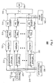
- FIG. 4 shows another alternative embodiment of a rake receiver 400.
- the individual programmable pulse generators 211 are replaced by a single pulse generator 410 followed by a demultiplexer 420, and a pulse sequence controller 430. This is advantageous in some applications where the multiple pulse generators 211 are difficult to implement, while the single pulse generator 410 and the demultiplexer 420 are relatively easy to implement.
- the demultiplexer 420 operates as a switch to route the pulses from the pulse generator 410 to the various multipliers 212 according to a pattern defined by the pulse sequence controller 430. Concurrently, the controller 430 also controls the pattern of pulses generated by the programmable pulse generator 410, so as to achieve the desired patterns of pulses for the multipliers 212.
- the invention also allows the option of feeding different pulse patterns to different rake fingers. This can be particularly advantageous in situations with severe multi-path, where the harm of inter-symbol interference can be larger than the advantage of additional detected signal.
- the pulse sequence controller, sample timing controller and weight/delay controller work in concert to optimize the performance of the rake receiver for the available channel, while fully exploiting the flexibility afforded by our invention.
Landscapes
- Engineering & Computer Science (AREA)
- Computer Networks & Wireless Communication (AREA)
- Signal Processing (AREA)
- Noise Elimination (AREA)
- Digital Transmission Methods That Use Modulated Carrier Waves (AREA)
- Superheterodyne Receivers (AREA)
Claims (10)
- Appareil destiné à détecter un signal radio émis à bande ultralarge (102), comprenant :un étage d'entrée (101) destiné à convertir une version reçue du signal radio émis à bande ultralarge en un signal électrique ;une pluralité de doigts de râteau (210, 310), chaque doigt de râteau étant destiné à traiter en parallèle le signal électrique, et chaque doigt de râteau comprenant en outre :un générateur d'impulsions programmable (211) destiné à générer une séquence d'impulsions à bande ultralarge ;un multiplicateur (212) connecté à une sortie de l'étage d'entrée et à une sortie d'un générateur d'impulsions programmable de manière à générer un signal associé de manière fonctionnelle au produit de la sortie de l'étage d'entrée par la sortie du générateur d'impulsions programmable ;un filtre passe-bas (213) destiné à filtrer la sortie du multiplicateur ;un bloc de pondération réglable (214) destiné à pondérer la sortie du filtre passe-bas ;un bloc d'échantillonnage - blocage (318) connecté entre le filtre passe-bas (213) et le bloc de pondération réglable (214), dans lequel le bloc d'échantillonnage - blocage (318) est un convertisseur analogique - numérique ; l'appareil comprenant en outre :un contrôleur de séquence d'impulsions (220) destiné à régler la synchronisation de chaque séquence d'impulsions à bande ultralarge de chaque générateur d'impulsions programmable dans chaque doigt de râteau ;un contrôleur de pondération (240, 340) destiné à régler les poids de chaque bloc de pondération réglable dans chaque doigt de râteau ;un bloc de sommation (250) configuré de manière à combiner une sortie de chaque doigt de râteau de façon à récupérer un signal qui correspond au signal radio émis à bande ultralarge ; etdans chaque doigt de râteau, un bloc de retard réglable (316) connecté entre le filtre passe-bas (213) du doigt de râteau et le bloc de sommation (250).
- Appareil destiné à détecter un signal radio émis à bande ultralarge, comprenant :un étage d'entrée (101) destiné à convertir une version reçue du signal radio émis à bande ultralarge en un signal électrique ;un générateur d'impulsions programmable (410) destiné à générer une séquence d'impulsions à bande ultralarge ;un démultiplexeur (420) connecté à une sortie du générateur d'impulsions programmable destiné à générer une pluralité de séquences d'impulsions à bande ultralarge ;un contrôleur de séquence d'impulsions (430) destiné à régler la synchronisation de chaque séquence d'impulsions ;une pluralité de doigts de râteau (310), chaque doigt de râteau étant destiné à traiter en parallèle le signal électrique, et chaque doigt de râteau comprenant en outre :un multiplicateur (212) connecté à une sortie de l'étage d'entrée et à une sortie du démultiplexeur de manière à générer un signal associé de manière fonctionnelle à un produit de la sortie de l'étage d'entrée par la sortie du générateur d'impulsions programmable ;un filtre passe-bas (213) destiné à filtrer la sortie du multiplicateur ;un bloc de pondération réglable (214) destiné à pondérer la sortie du filtre passe-bas ;un bloc d'échantillonnage - blocage (318) connecté entre le filtre passe-bas (213) et le bloc de pondération réglable (214), dans lequel le bloc d'échantillonnage - blocage (318) est un convertisseur analogique - numérique ; l'appareil comprenant en outre :un contrôleur de pondération (340) destiné à régler les poids de chaque bloc de pondération réglable dans chaque doigt de râteau ;un bloc de sommation (250) configuré de manière à combiner une sortie de chaque doigt de râteau de façon à récupérer un signal qui correspond au signal radio émis à bande ultralarge ; etdans chaque doigt de râteau, un bloc de retard réglable (316) connecté entre le filtre passe-bas (213) du doigt de râteau et le bloc de sommation (250).
- Appareil selon la revendication 1 ou la revendication 2, dans lequel un motif de la séquence d'impulsions est identique à un motif d'impulsions utilisé de manière à étaler le signal émis dans un émetteur.
- Appareil selon la revendication 1 ou la revendication 2, dans lequel la synchronisation de chaque séquence d'impulsions correspond à un retard d'un trajet dans un canal à propagation par trajets multiples utilisé pour émettre le signal radio.
- Appareil selon la revendication 1 ou la revendication 2, dans lequel le filtre passe-bas (213) génère une sortie proportionnelle à une intégrale par rapport au temps d'une entrée du filtre passe-bas.
- Appareil selon la revendication 1 ou la revendication 2, dans lequel le filtre passe-bas (213) est un filtre à intégration et vidage.
- Appareil selon la revendication 1 ou la revendication 2, dans lequel le signal électrique est un signal complexe qui se compose d'une composante en phase et d'une composante en quadrature.
- Appareil selon la revendication 4, dans lequel le signal électrique se présente sous la forme d'un signal numérique.
- Appareil selon la revendication 1 ou la revendication 2, dans lequel le bloc de retard réglable (316) est adapté de manière à générer un signal de sortie proportionnel à une version retardée d'un signal d'entrée, la valeur du retard étant déterminée par une entrée de commande (340).
- Procédé destiné à détecter un signal radio émis à bande ultralarge, comprenant les étapes consistant à :convertir une version reçue du signal radio émis à bande ultralarge en un signal électrique ;traiter en parallèle le signal électrique dans une pluralité de doigts de râteau, le traitement dans chaque doigt comprenant les sept étapes suivantes consistant à :générer une séquence d'impulsions à bande ultralarge avec une synchronisation réglable ;multiplier la séquence d'impulsions à bande ultralarge par le signal électrique ;filtrer à l'aide d'un filtre passe-bas le signal produit par la multiplication ;échantillonner le signal filtré par le filtre passe-bas ;pondérer le signal échantillonné avec un poids réglable ;retarder le signal pondéré, etsommer les signaux retardés de chaque doigt de manière à récupérer un signal qui correspond au signal radio émis à bande ultralarge.
Applications Claiming Priority (3)
| Application Number | Priority Date | Filing Date | Title |
|---|---|---|---|
| US10/376,686 US20040170218A1 (en) | 2003-03-01 | 2003-03-01 | Rake receiver for ultra wide bandwidth communications systems |
| US376686 | 2003-03-01 | ||
| PCT/JP2004/002453 WO2004079940A1 (fr) | 2003-03-01 | 2004-02-27 | Appareil et procede pour detecter un signal radio transmis |
Publications (2)
| Publication Number | Publication Date |
|---|---|
| EP1495553A1 EP1495553A1 (fr) | 2005-01-12 |
| EP1495553B1 true EP1495553B1 (fr) | 2010-04-14 |
Family
ID=32907975
Family Applications (1)
| Application Number | Title | Priority Date | Filing Date |
|---|---|---|---|
| EP04715536A Expired - Fee Related EP1495553B1 (fr) | 2003-03-01 | 2004-02-27 | Appareil et procédé pour detecter un signal radio transmis |
Country Status (6)
| Country | Link |
|---|---|
| US (1) | US20040170218A1 (fr) |
| EP (1) | EP1495553B1 (fr) |
| JP (1) | JP2006519566A (fr) |
| CN (1) | CN1698283B (fr) |
| DE (1) | DE602004026509D1 (fr) |
| WO (1) | WO2004079940A1 (fr) |
Families Citing this family (8)
| Publication number | Priority date | Publication date | Assignee | Title |
|---|---|---|---|---|
| US20050078735A1 (en) * | 2003-07-18 | 2005-04-14 | David Baker | Communications systems and methods |
| US7106780B2 (en) * | 2003-09-30 | 2006-09-12 | Interdigital Technology Corporation | Rake-based CDMA receivers for multiple receiver antennas |
| FI20045181A0 (fi) * | 2004-05-19 | 2004-05-19 | Oulun Ylipisto | Menetelmä ja laite ajoitussignaalien tuottamiseksi ultralaajakaistapulssigeneraattorille |
| US7606295B2 (en) * | 2005-02-24 | 2009-10-20 | Interdigital Technology Corporation | Generalized rake receiver for wireless communication |
| US7796686B2 (en) | 2005-11-14 | 2010-09-14 | University Of South Florida | Adaptive ultrawideband receiver and method of use |
| CN100505567C (zh) * | 2005-12-31 | 2009-06-24 | 北京大学 | 一种加权非相干超宽带接收方法及装置 |
| CN101394643B (zh) * | 2007-09-21 | 2012-07-11 | 刘伯安 | 发射和接收超宽带脉冲或脉冲序列的系统和方法 |
| WO2017016579A1 (fr) | 2015-07-24 | 2017-02-02 | Huawei Technologies Co., Ltd. | Appareil et procédé de communication |
Family Cites Families (7)
| Publication number | Priority date | Publication date | Assignee | Title |
|---|---|---|---|---|
| JPH10190528A (ja) * | 1996-12-25 | 1998-07-21 | Matsushita Electric Ind Co Ltd | スペクトル拡散受信機 |
| JP3411505B2 (ja) * | 1997-09-30 | 2003-06-03 | シャープ株式会社 | スペクトル拡散通信装置 |
| US7280607B2 (en) * | 1997-12-12 | 2007-10-09 | Freescale Semiconductor, Inc. | Ultra wide bandwidth communications method and system |
| US6330271B1 (en) * | 1998-10-13 | 2001-12-11 | Telefonaktiebolaget Lm Ericsson (Publ) | CDMA receiver that shares a tracking device among multiple rake branches |
| US6956841B1 (en) * | 2000-05-24 | 2005-10-18 | Nokia Networks Oy | Receiver and method of receiving a desired signal |
| AU2000258822A1 (en) * | 2000-05-26 | 2001-12-11 | Xtremespectrum, Inc. | Ultra wide bandwidth spread-spectrum communications method and system |
| US7292622B2 (en) * | 2002-10-08 | 2007-11-06 | Freescale Semiconductor, Inc. | Method and apparatus for raking in a wireless network |
-
2003
- 2003-03-01 US US10/376,686 patent/US20040170218A1/en not_active Abandoned
-
2004
- 2004-02-27 WO PCT/JP2004/002453 patent/WO2004079940A1/fr active Application Filing
- 2004-02-27 EP EP04715536A patent/EP1495553B1/fr not_active Expired - Fee Related
- 2004-02-27 CN CN200480000308.0A patent/CN1698283B/zh not_active Expired - Fee Related
- 2004-02-27 JP JP2006507650A patent/JP2006519566A/ja active Pending
- 2004-02-27 DE DE602004026509T patent/DE602004026509D1/de not_active Expired - Lifetime
Also Published As
| Publication number | Publication date |
|---|---|
| US20040170218A1 (en) | 2004-09-02 |
| CN1698283B (zh) | 2010-04-28 |
| DE602004026509D1 (de) | 2010-05-27 |
| CN1698283A (zh) | 2005-11-16 |
| JP2006519566A (ja) | 2006-08-24 |
| WO2004079940A1 (fr) | 2004-09-16 |
| EP1495553A1 (fr) | 2005-01-12 |
Similar Documents
| Publication | Publication Date | Title |
|---|---|---|
| EP1774670B1 (fr) | Utilisation de filtres adaptatifs dans des systemes sans fil amrc utilisant des signaux pilotes | |
| CA2552443C (fr) | Dispositif et procede d'elimination d'interferences du spectre d'etalement | |
| CN100483963C (zh) | 正交下混频数字模版匹配的脉冲超宽带无线信号接收方法 | |
| CN101371452B (zh) | 针对无线通信使用功率估计和追踪的干扰消除 | |
| US5648983A (en) | CDMA rake receiver with sub-chip resolution | |
| EP2230772A2 (fr) | Annulation d'interférences dans un système de communication à spectre étalé | |
| WO2005125033A1 (fr) | Recepteur adaptatif, essentiellement numerique, a bande ultra-large | |
| US7756196B1 (en) | Efficient adaptive filters for CDMA wireless systems | |
| WO2009135633A9 (fr) | Détection de signal multi-bande par auto-corrélation | |
| EP1495553B1 (fr) | Appareil et procédé pour detecter un signal radio transmis | |
| EP1279239B1 (fr) | Filtre adapte et recepteur destines a un systeme de radiocommunication mobile | |
| KR20020043252A (ko) | 트랙킹 방법, 레이크 수신기 및 확산 스펙트럼 통신 시스템 | |
| US7356100B2 (en) | Estimating channel impulse response and equalizer coefficients in UWB communication systems | |
| WO2007119207A2 (fr) | Estimation de canal ameliore pour des canaux dedies utilisateurs | |
| US7436916B2 (en) | Pulse modulator and PPM demodulation determining circuit employed in ultra wideband wireless communications | |
| US20050013390A1 (en) | Hybrid UWB receiver with matched filters and pulse correlator | |
| KR20060114747A (ko) | 초광대역 무선통신 시스템의 기저대역수신장치 | |
| Goyal et al. | Ultra Wideband PAM Modulation and Reception in UWB Multi Path channel Using Rake Configurations | |
| KR101210608B1 (ko) | 임펄스 신호기반 초광대역 무선통신 시스템의 효율적 수신구조를 이용한 자동 이득 제어 장치 및 방법 | |
| CN101741405A (zh) | 一种适用于脉冲超宽带系统的接收方法 | |
| GB2404124A (en) | Correlating a UWB signal with a stored pilot UWB signal | |
| Bianchi et al. | Frequency domain detection for ultra-wideband communications in the indoor environment | |
| JP2005277642A (ja) | Uwb通信装置 | |
| Fayadh et al. | Implementation of new combiner for indoor UWB wireless rake receiver | |
| KR20070022081A (ko) | 적응형 디지털 초 광대역 수신기 |
Legal Events
| Date | Code | Title | Description |
|---|---|---|---|
| PUAI | Public reference made under article 153(3) epc to a published international application that has entered the european phase |
Free format text: ORIGINAL CODE: 0009012 |
|
| 17P | Request for examination filed |
Effective date: 20041116 |
|
| AK | Designated contracting states |
Kind code of ref document: A1 Designated state(s): AT BE BG CH CY CZ DE DK EE ES FI FR GB GR HU IE IT LI LU MC NL PT RO SE SI SK TR |
|
| AX | Request for extension of the european patent |
Extension state: AL LT LV MK |
|
| RIN1 | Information on inventor provided before grant (corrected) |
Inventor name: MOLISCH, ANDREAS Inventor name: VANNUCCI, GIOVANNI Inventor name: ZHANG, JINYUN |
|
| RAP1 | Party data changed (applicant data changed or rights of an application transferred) |
Owner name: MITSUBISHI DENKI KABUSHIKI KAISHA |
|
| DAX | Request for extension of the european patent (deleted) | ||
| RBV | Designated contracting states (corrected) |
Designated state(s): DE FR GB |
|
| 17Q | First examination report despatched |
Effective date: 20061220 |
|
| GRAP | Despatch of communication of intention to grant a patent |
Free format text: ORIGINAL CODE: EPIDOSNIGR1 |
|
| RTI1 | Title (correction) |
Free format text: APPARATUS AND METHOD FOR DETECTING TRANSMITTED RADIO SIGNAL |
|
| GRAS | Grant fee paid |
Free format text: ORIGINAL CODE: EPIDOSNIGR3 |
|
| GRAA | (expected) grant |
Free format text: ORIGINAL CODE: 0009210 |
|
| AK | Designated contracting states |
Kind code of ref document: B1 Designated state(s): DE FR GB |
|
| REG | Reference to a national code |
Ref country code: GB Ref legal event code: FG4D |
|
| REF | Corresponds to: |
Ref document number: 602004026509 Country of ref document: DE Date of ref document: 20100527 Kind code of ref document: P |
|
| PLBE | No opposition filed within time limit |
Free format text: ORIGINAL CODE: 0009261 |
|
| STAA | Information on the status of an ep patent application or granted ep patent |
Free format text: STATUS: NO OPPOSITION FILED WITHIN TIME LIMIT |
|
| 26N | No opposition filed |
Effective date: 20110117 |
|
| PGFP | Annual fee paid to national office [announced via postgrant information from national office to epo] |
Ref country code: GB Payment date: 20130228 Year of fee payment: 10 Ref country code: DE Payment date: 20130220 Year of fee payment: 10 Ref country code: FR Payment date: 20130301 Year of fee payment: 10 |
|
| REG | Reference to a national code |
Ref country code: DE Ref legal event code: R119 Ref document number: 602004026509 Country of ref document: DE |
|
| GBPC | Gb: european patent ceased through non-payment of renewal fee |
Effective date: 20140227 |
|
| REG | Reference to a national code |
Ref country code: FR Ref legal event code: ST Effective date: 20141031 |
|
| REG | Reference to a national code |
Ref country code: DE Ref legal event code: R119 Ref document number: 602004026509 Country of ref document: DE Effective date: 20140902 |
|
| PG25 | Lapsed in a contracting state [announced via postgrant information from national office to epo] |
Ref country code: DE Free format text: LAPSE BECAUSE OF NON-PAYMENT OF DUE FEES Effective date: 20140902 Ref country code: FR Free format text: LAPSE BECAUSE OF NON-PAYMENT OF DUE FEES Effective date: 20140228 Ref country code: GB Free format text: LAPSE BECAUSE OF NON-PAYMENT OF DUE FEES Effective date: 20140227 |