EP1494234A2 - Aufzeichnungsmedium, Aufzeichnungs-/Wiedergabevorrichtung, und Aufzeichnungs-/Wiedergabeverfahren - Google Patents
Aufzeichnungsmedium, Aufzeichnungs-/Wiedergabevorrichtung, und Aufzeichnungs-/Wiedergabeverfahren Download PDFInfo
- Publication number
- EP1494234A2 EP1494234A2 EP04015264A EP04015264A EP1494234A2 EP 1494234 A2 EP1494234 A2 EP 1494234A2 EP 04015264 A EP04015264 A EP 04015264A EP 04015264 A EP04015264 A EP 04015264A EP 1494234 A2 EP1494234 A2 EP 1494234A2
- Authority
- EP
- European Patent Office
- Prior art keywords
- area
- recording
- management information
- recorded
- data
- Prior art date
- Legal status (The legal status is an assumption and is not a legal conclusion. Google has not performed a legal analysis and makes no representation as to the accuracy of the status listed.)
- Withdrawn
Links
Images


Classifications
-
- G—PHYSICS
- G11—INFORMATION STORAGE
- G11B—INFORMATION STORAGE BASED ON RELATIVE MOVEMENT BETWEEN RECORD CARRIER AND TRANSDUCER
- G11B7/00—Recording or reproducing by optical means, e.g. recording using a thermal beam of optical radiation by modifying optical properties or the physical structure, reproducing using an optical beam at lower power by sensing optical properties; Record carriers therefor
- G11B7/007—Arrangement of the information on the record carrier, e.g. form of tracks, actual track shape, e.g. wobbled, or cross-section, e.g. v-shaped; Sequential information structures, e.g. sectoring or header formats within a track
-
- G—PHYSICS
- G11—INFORMATION STORAGE
- G11B—INFORMATION STORAGE BASED ON RELATIVE MOVEMENT BETWEEN RECORD CARRIER AND TRANSDUCER
- G11B27/00—Editing; Indexing; Addressing; Timing or synchronising; Monitoring; Measuring tape travel
- G11B27/10—Indexing; Addressing; Timing or synchronising; Measuring tape travel
- G11B27/102—Programmed access in sequence to addressed parts of tracks of operating record carriers
- G11B27/105—Programmed access in sequence to addressed parts of tracks of operating record carriers of operating discs
-
- G—PHYSICS
- G11—INFORMATION STORAGE
- G11B—INFORMATION STORAGE BASED ON RELATIVE MOVEMENT BETWEEN RECORD CARRIER AND TRANSDUCER
- G11B20/00—Signal processing not specific to the method of recording or reproducing; Circuits therefor
- G11B20/10—Digital recording or reproducing
- G11B20/12—Formatting, e.g. arrangement of data block or words on the record carriers
- G11B20/1217—Formatting, e.g. arrangement of data block or words on the record carriers on discs
-
- G—PHYSICS
- G11—INFORMATION STORAGE
- G11B—INFORMATION STORAGE BASED ON RELATIVE MOVEMENT BETWEEN RECORD CARRIER AND TRANSDUCER
- G11B27/00—Editing; Indexing; Addressing; Timing or synchronising; Monitoring; Measuring tape travel
-
- G—PHYSICS
- G11—INFORMATION STORAGE
- G11B—INFORMATION STORAGE BASED ON RELATIVE MOVEMENT BETWEEN RECORD CARRIER AND TRANSDUCER
- G11B27/00—Editing; Indexing; Addressing; Timing or synchronising; Monitoring; Measuring tape travel
- G11B27/10—Indexing; Addressing; Timing or synchronising; Measuring tape travel
- G11B27/19—Indexing; Addressing; Timing or synchronising; Measuring tape travel by using information detectable on the record carrier
- G11B27/24—Indexing; Addressing; Timing or synchronising; Measuring tape travel by using information detectable on the record carrier by sensing features on the record carrier other than the transducing track ; sensing signals or marks recorded by another method than the main recording
-
- G—PHYSICS
- G11—INFORMATION STORAGE
- G11B—INFORMATION STORAGE BASED ON RELATIVE MOVEMENT BETWEEN RECORD CARRIER AND TRANSDUCER
- G11B27/00—Editing; Indexing; Addressing; Timing or synchronising; Monitoring; Measuring tape travel
- G11B27/10—Indexing; Addressing; Timing or synchronising; Measuring tape travel
- G11B27/19—Indexing; Addressing; Timing or synchronising; Measuring tape travel by using information detectable on the record carrier
- G11B27/28—Indexing; Addressing; Timing or synchronising; Measuring tape travel by using information detectable on the record carrier by using information signals recorded by the same method as the main recording
- G11B27/30—Indexing; Addressing; Timing or synchronising; Measuring tape travel by using information detectable on the record carrier by using information signals recorded by the same method as the main recording on the same track as the main recording
- G11B27/3027—Indexing; Addressing; Timing or synchronising; Measuring tape travel by using information detectable on the record carrier by using information signals recorded by the same method as the main recording on the same track as the main recording used signal is digitally coded
-
- G—PHYSICS
- G11—INFORMATION STORAGE
- G11B—INFORMATION STORAGE BASED ON RELATIVE MOVEMENT BETWEEN RECORD CARRIER AND TRANSDUCER
- G11B27/00—Editing; Indexing; Addressing; Timing or synchronising; Monitoring; Measuring tape travel
- G11B27/10—Indexing; Addressing; Timing or synchronising; Measuring tape travel
- G11B27/19—Indexing; Addressing; Timing or synchronising; Measuring tape travel by using information detectable on the record carrier
- G11B27/28—Indexing; Addressing; Timing or synchronising; Measuring tape travel by using information detectable on the record carrier by using information signals recorded by the same method as the main recording
- G11B27/32—Indexing; Addressing; Timing or synchronising; Measuring tape travel by using information detectable on the record carrier by using information signals recorded by the same method as the main recording on separate auxiliary tracks of the same or an auxiliary record carrier
- G11B27/327—Table of contents
- G11B27/329—Table of contents on a disc [VTOC]
-
- G—PHYSICS
- G11—INFORMATION STORAGE
- G11B—INFORMATION STORAGE BASED ON RELATIVE MOVEMENT BETWEEN RECORD CARRIER AND TRANSDUCER
- G11B20/00—Signal processing not specific to the method of recording or reproducing; Circuits therefor
- G11B20/10—Digital recording or reproducing
- G11B20/12—Formatting, e.g. arrangement of data block or words on the record carriers
- G11B20/1217—Formatting, e.g. arrangement of data block or words on the record carriers on discs
- G11B2020/1218—Formatting, e.g. arrangement of data block or words on the record carriers on discs wherein the formatting concerns a specific area of the disc
- G11B2020/1228—Formatting, e.g. arrangement of data block or words on the record carriers on discs wherein the formatting concerns a specific area of the disc middle zone or outer guard area of a multilayer disc
-
- G—PHYSICS
- G11—INFORMATION STORAGE
- G11B—INFORMATION STORAGE BASED ON RELATIVE MOVEMENT BETWEEN RECORD CARRIER AND TRANSDUCER
- G11B20/00—Signal processing not specific to the method of recording or reproducing; Circuits therefor
- G11B20/10—Digital recording or reproducing
- G11B20/12—Formatting, e.g. arrangement of data block or words on the record carriers
- G11B20/1217—Formatting, e.g. arrangement of data block or words on the record carriers on discs
- G11B2020/1218—Formatting, e.g. arrangement of data block or words on the record carriers on discs wherein the formatting concerns a specific area of the disc
- G11B2020/1232—Formatting, e.g. arrangement of data block or words on the record carriers on discs wherein the formatting concerns a specific area of the disc sector, i.e. the minimal addressable physical data unit
-
- G—PHYSICS
- G11—INFORMATION STORAGE
- G11B—INFORMATION STORAGE BASED ON RELATIVE MOVEMENT BETWEEN RECORD CARRIER AND TRANSDUCER
- G11B20/00—Signal processing not specific to the method of recording or reproducing; Circuits therefor
- G11B20/10—Digital recording or reproducing
- G11B20/12—Formatting, e.g. arrangement of data block or words on the record carriers
- G11B2020/1264—Formatting, e.g. arrangement of data block or words on the record carriers wherein the formatting concerns a specific kind of data
- G11B2020/1265—Control data, system data or management information, i.e. data used to access or process user data
- G11B2020/1267—Address data
- G11B2020/1268—Address in pregroove [ADIP] information
-
- G—PHYSICS
- G11—INFORMATION STORAGE
- G11B—INFORMATION STORAGE BASED ON RELATIVE MOVEMENT BETWEEN RECORD CARRIER AND TRANSDUCER
- G11B20/00—Signal processing not specific to the method of recording or reproducing; Circuits therefor
- G11B20/10—Digital recording or reproducing
- G11B20/12—Formatting, e.g. arrangement of data block or words on the record carriers
- G11B2020/1264—Formatting, e.g. arrangement of data block or words on the record carriers wherein the formatting concerns a specific kind of data
- G11B2020/1265—Control data, system data or management information, i.e. data used to access or process user data
- G11B2020/1285—Status of the record carrier, e.g. space bit maps, flags indicating a formatting status or a write permission
-
- G—PHYSICS
- G11—INFORMATION STORAGE
- G11B—INFORMATION STORAGE BASED ON RELATIVE MOVEMENT BETWEEN RECORD CARRIER AND TRANSDUCER
- G11B2220/00—Record carriers by type
- G11B2220/20—Disc-shaped record carriers
- G11B2220/21—Disc-shaped record carriers characterised in that the disc is of read-only, rewritable, or recordable type
- G11B2220/215—Recordable discs
- G11B2220/216—Rewritable discs
-
- G—PHYSICS
- G11—INFORMATION STORAGE
- G11B—INFORMATION STORAGE BASED ON RELATIVE MOVEMENT BETWEEN RECORD CARRIER AND TRANSDUCER
- G11B2220/00—Record carriers by type
- G11B2220/20—Disc-shaped record carriers
- G11B2220/21—Disc-shaped record carriers characterised in that the disc is of read-only, rewritable, or recordable type
- G11B2220/215—Recordable discs
- G11B2220/218—Write-once discs
-
- G—PHYSICS
- G11—INFORMATION STORAGE
- G11B—INFORMATION STORAGE BASED ON RELATIVE MOVEMENT BETWEEN RECORD CARRIER AND TRANSDUCER
- G11B2220/00—Record carriers by type
- G11B2220/20—Disc-shaped record carriers
- G11B2220/23—Disc-shaped record carriers characterised in that the disc has a specific layer structure
- G11B2220/235—Multilayer discs, i.e. multiple recording layers accessed from the same side
- G11B2220/237—Multilayer discs, i.e. multiple recording layers accessed from the same side having exactly two recording layers
-
- G—PHYSICS
- G11—INFORMATION STORAGE
- G11B—INFORMATION STORAGE BASED ON RELATIVE MOVEMENT BETWEEN RECORD CARRIER AND TRANSDUCER
- G11B2220/00—Record carriers by type
- G11B2220/20—Disc-shaped record carriers
- G11B2220/25—Disc-shaped record carriers characterised in that the disc is based on a specific recording technology
- G11B2220/2537—Optical discs
- G11B2220/2541—Blu-ray discs; Blue laser DVR discs
-
- G—PHYSICS
- G11—INFORMATION STORAGE
- G11B—INFORMATION STORAGE BASED ON RELATIVE MOVEMENT BETWEEN RECORD CARRIER AND TRANSDUCER
- G11B2220/00—Record carriers by type
- G11B2220/20—Disc-shaped record carriers
- G11B2220/25—Disc-shaped record carriers characterised in that the disc is based on a specific recording technology
- G11B2220/2537—Optical discs
- G11B2220/2562—DVDs [digital versatile discs]; Digital video discs; MMCDs; HDCDs
- G11B2220/257—DVDs belonging to the plus family, i.e. +R, +RW, +VR
-
- G—PHYSICS
- G11—INFORMATION STORAGE
- G11B—INFORMATION STORAGE BASED ON RELATIVE MOVEMENT BETWEEN RECORD CARRIER AND TRANSDUCER
- G11B2220/00—Record carriers by type
- G11B2220/20—Disc-shaped record carriers
- G11B2220/25—Disc-shaped record carriers characterised in that the disc is based on a specific recording technology
- G11B2220/2537—Optical discs
- G11B2220/2562—DVDs [digital versatile discs]; Digital video discs; MMCDs; HDCDs
- G11B2220/2575—DVD-RAMs
Definitions
- the present invention relates to a recording medium, such as a disc, that has a plurality of information recording layers and on which data can be rewritten; a recording and reproduction apparatus; and a recording and reproduction method, which are compatible with the recording medium.
- optical recording media capable of optically recording and reproducing information
- optical discs, optical cards, and the like are known.
- Information is recorded on and reproduced from these optical recording media by using laser light of a semiconductor laser, etc., as a light source and by radiating a very finely focused optical beam via a lens.
- the shortening of a wavelength of a light source has a limit, that is, up to the ultraviolet region, and the pit size can only be reduced up to the size at which a transfer can be performed on the disc during cutting.
- the attempts for increasing the recording density will reach a limit at some future time in the two-dimensional area of the disc.
- a technique for achieving a larger capacity has also been considered in a three-dimensional manner. That is, a multilayer disc which is formed in such a manner that information recording layers are layered to increase the density of recording information in the thickness direction of the disc has attracted attention.
- the multilayer recording medium in which recording layers are layered have features such that the recording capacity can be doubled according to the number of recording layers and are easy to combine with another high-density recording technology.
- the multilayer recording media have already been put into practical use as, for example, a DVD (Digital Versatile Disc)-ROMs, which are read-only optical discs.
- recordable multilayer recording media in which recordable recording layers of phase-change material, magneto-optical material, die material, etc., are layered, are expected to become commercially practical.
- realization of multilayer recording layers are also expected in write-once discs called DVD-R, DVD+R, etc., or in rewritable discs called DVD-RW, DVD+RW, DVD+RAM, etc.
- a method called a "parallel track path” and a method called an "opposite track path” are known. These methods will be described later with reference to Figs. 4A, 4B, 5A, and 5B.
- the opposite track path is such that the address advancing direction is the opposite direction between odd-numbered recording layers and even-numbered recording layers. For example, in the first layer (layer 0), recording or reproduction is performed from the inner area toward the outer area, and thereafter, in the second layer (layer 1), recording or reproduction is performed in loopback from the outer area toward the inner area.
- a lead-in zone is formed in the inner area, and following it, a data zone in which user data is recorded is formed. In this data zone, recording or reproduction is performed from the inner area toward the outer area.
- the largest usable address as the data zone (the address in the outermost area where user data recording is possible in the layer 0) is determined in advance, and user data recording is performed up to a required address with the maximum address being the limit.
- address UD-END #1 the address of the end where user data recording is performed in the layer 0 is shown as address UD-END #1.
- the user data recording proceeds to the layer 1, and this time, the recording is performed from the outer area toward the inner area.
- the area inner of the end of user data recording is assumed to be a lead-out.
- the address UD-END #1 is an address as a position where the recording proceeds from the layer 0 to the layer 1, that is, as an inter-layer transition position.
- a middle area is formed in both the layers 0 and 1.
- This middle area has a function as a guard area in which dummy data is recorded continuously to the outer-area end portion where user data is recorded.
- a middle area which is made to be a recorded area by dummy data, is formed.
- a data rewritable disc will be considered.
- the rewritable disc for example, as shown in part (a) of Fig. 16, even after the user data #1 is recorded, the content can be deleted to newly write data.
- Part (b) of Fig. 16 shows an example in which user data #1 of part (a) of Fig. 16 is deleted so as to be rewritten with user data #2.
- Part (c) of Fig. 16 shows an example in which user data #1 of part (a) of Fig. 16 is deleted so as to be rewritten with user data #3.
- the inter-layer transition position moves to address UD-END #2.
- the inter-layer transition position moves to address UD-END #3.
- the inter-layer transition position is not constant as in the above-described examples of parts (a), (b), and (c) of Fig. 16 because the position is made the maximum address specified in the disc format, and also, the position is changed according to the amount of user data to be recorded and from instructions from the host (application).
- part (a) of Fig. 16 shows a case in which the layer 0 is not used up to the maximum address at which the user data can be recorded, and the recording proceeds to the layer 1.
- Part (b) of Fig. 16 shows a case in which, when user data #1 of part (a) of Fig. 16 is rewritten with user data #2, inter-layer loopback is performed at a lower address.
- Part (c) of Fig. 16 shows a case in which, when user data #1 of part (a) of Fig. 16 is rewritten with user data #3, inter-layer loopback is performed after the user data is used up to the maximum address of the layer 0, at which the user data can be recorded.
- the range of the middle area varies.
- each area in each area (lead-in, data zone, lead-out, middle area), in each sector forming the area, information as zone type indicating area attributes is recorded. This allows each area to be distinguished.
- each sector serving as a lead-in zone it is shown in the header information thereof that the sector is a sector forming a lead-in. zone. Furthermore, in each sector in the data zone, the header information indicates that the sector is a sector forming the data zone. The same applies to the lead-out and the middle area.
- the process for rewriting the attributes of the sector contained in the range B in the figure from the middle area to the data zone as shown in part (c) of Fig. 16 is realized by the user data recording itself. That is, since sector recording of the attributes as the user data is performed in the sector which was a middle area, it is not necessary to go through the trouble of rewriting the attribute information of the sector later.
- the process for rewriting the attributes of the sector contained in the range A in the figure from the data zone to the middle area as shown in part (b) of Fig. 16 must be performed separately from the user data recording. For this reason, the process is performed when a special operation is required, for example, after the user data recording is completed. For example, it is a case in which a finalizing process is performed.
- the middle area is also formed if necessary according to the state of the user data recording at that time. That is, a state is reached in which the area after the inter-layer transition position UD-END is correctly a middle area.
- the middle area is formed (the formation of the middle area according to the current inter-layer transition position UD-END), for example, during a specific process such as a finalizing process, there is a time difference from when the user data is recorded until the formation of the middle area in accordance with the user data recording state, and in some cases, the disc before the middle area is formed is ejected from the device. Also, there are cases in which the disc exists in which the middle area in accordance with the user data recording state is not formed due to the operation of turning off the power, power stoppage, etc., during that time.
- the recording and reproduction apparatus confirms whether or not the middle area (the middle area corresponding to the current inter-layer transition position UD-END) is not yet formed and forms a middle area if necessary.
- an object of the present invention is to make a middle area confirmation process easier and to realize speeding up of a specific process such as a finalizing process on a rewritable recording medium that has a plurality of recording layers and in which an opposite track path is adopted.
- the present invention provides a recording medium having a plurality of recording layers, on which data can be rewritten, and on and from which user data is recorded and reproduced by an opposite track path method in which the address advancing direction is the opposite direction between odd-numbered recording layers and even-numbered recording layers, the recording medium including: a guard intermediate area (middle area) to be formed by assuming, as one end, the inter-layer transition position at which the recording proceeds from a certain recording medium to the next recording medium when user data is to be recorded; and a management information area in which intermediate-area management information indicating whether or not the guard intermediate area has already been formed is to be recorded.
- a guard intermediate area middle area
- the present invention provides a recording and reproduction apparatus incorporating the recording medium, the recording and reproduction apparatus including: a recording and reproduction section for recording and reproducing data on and from each of the recording layers; a management information updating processing section for updating intermediate-area management information when the guard intermediate area is to be formed according to the user data recording state or when the guard intermediate area is formed; and an intermediate-area formation processing section for determining whether or not the guard intermediate area needs to be formed by referring to the intermediate-area management information and for forming the guard intermediate area according to the determination result.
- the management information updating processing section may record an address value indicating the new inter-layer transition position in the management information area and may update the value of the intermediate-area management information to a value indicating "not yet formed".
- the management information updating processing section may update the value of the intermediate-area management information to a value indicating that the guard intermediate area is "formed” in accordance with the fact that the guard intermediate area is formed on the basis of the address value indicating the inter-layer transition position.
- the present invention provides a recording and reproduction method incorporating a recording medium, the recording and reproduction method including: a first updating step of updating the value of the intermediate-area management information to a value indicating "not yet formed" when the guard intermediate area is to be formed according to the user data recording state; a determination step of determining whether or not the guard intermediate area needs to be formed by referring to the intermediate-area management information; a forming step of forming the guard intermediate area according to the result of the determination step; and a second updating step of updating the value of the intermediate-area management information to a value indicating "formed” according to the formation of the guard intermediate area.
- the address value indicating the new inter-layer transition position may be recorded in the management information area, and the value of the intermediate-area management information may be updated to a value indicating that the guard intermediate area is "not yet formed".
- the value indicating the intermediate-area management information may be updated to a value indicating that the guard intermediate area is "formed" according to the formation of the guard intermediate area on the basis of the address value indicating the inter-layer transition position.
- intermediate-area management information indicating whether or not the guard intermediate area (middle area) which assumes the inter-layer transition position (inter-layer loopback address) which is determined in accordance with the recording of the user data as one end has already been formed is recorded within a predetermined management information area (for example, lead in). Therefore, it is possible for the recording and reproduction apparatus to determine whether or not the middle area needs to be formed according to the intermediate-area management information.
- the intermediate-area management information is made to have a value indicating "non-formation" in a state in which the inter-layer transition position changes as a result of user data recording and to have a value indicating "formed” in accordance with the fact that the guard intermediate area is formed on the basis of the address value indicating the inter-layer transition position.
- a DVD Digital Versatile Disc
- a disk drive device (to be described later) is assumed to be a device for performing recording on and reproduction from a disc as a DVD.
- DVD+R which is a rewritable disc, as an example.
- the disk drive unit recording device
- information unique to the disc is read from the ADIP (ADdress In Pre-groove) information embossed in the wobbling grooves on the recording surface, and it is recognized that the disc is a disc as DVD+RW.
- the recognized disc is then sometimes ejected from the recording device and loaded into the recording device again. At this time, there are cases in which the disc is loaded into the same recording device again or is loaded into another recording device or reproduction device for data exchange.
- the DVD logical format is formulated by making recording. compatibility and reproduction compatibility smooth among the devices.
- an information zone is formed from the inner area of the disc toward the outer area.
- This information zone is an area containing all the information required to ensure data recording compatibility and reproduction compatibility.
- the information zone is mainly composed of the following five areas.
- the lead-in zone, the data zone, and the lead-out zone exist in an area which can be accessed even by a read-only device without any trouble.
- the inner drive area and the outer drive area are areas which are exclusively used for the recording device.
- the laser power during recording needs to be adjusted so as to be capable of forming a correct recording mark.
- a test zone which can be used for test recording for determining the optimum recording conditions and an area in which management information related to the recording conditions are formed in the inner drive area and the outer drive area.
- the test zone since the recording state becomes nonuniform due to test recording, there is no guarantee that the test zone is accessed without any trouble by the read-only device. Therefore, the test zone is arranged in an area which cannot be accessed by the read-only device.
- a physical sector number (PSN) is given as absolute position information on the disc.
- the value of the physical sector number increases from the inner area of the disc toward the outer area.
- the data zone is basically an area where user data is written, and in the lead-in zone, management information is written. Furthermore, in the lead-out zone, for example, dummy data is written for the purpose of maintaining compatibility with a read-only disc, and in the case of a DVD+RW disc, there are cases in which management information having substantially the same content as that of the lead-in zone is recorded.
- the whole information zone is a data rewritable area, and wobbling grooves are formed as recording tracks.
- tracks can be appropriately traced during recording.
- ADIP information is recorded.
- the physical sector number PSN is recorded as the ADIP address in the information zone.
- PFI Physical Format Information
- a finalizing process is performed, so that the management information of the lead-in zone is finally updated, and a process for forming a lead-out zone is performed, completing the configuration shown in Fig. 1.
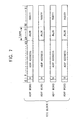
- Fig. 2 illustrates a sector structure
- one sector is composed of an ID field of 4 bytes, an IED field of 2 bytes, a reserved field of 6 bytes, a main data field of 2048 bytes, and an EDC field of 4 bytes.
- the header information of the sector is recorded.
- an error detection code for the data of the ID field is recorded.
- main data field main data of 2048 bytes is recorded.
- user data is recorded as the main data.
- management information of the content shown in Figs. 10 to 13 is recorded as the main data.
- dummy data is recorded as the main data.
- an error detection code for the data from the ID field to the main data field is recorded.
- the PSN Physical Sector Number
- the PSN Physical Sector Number
- the sector information is recorded.
- the content of this sector information is shown in part (c) of Fig. 2.
- the bit b24 the layer number of the recording layer including that sector is recorded.
- bit b25 for example, the data type indicating that the data is rewritable data is recorded.
- the zone type is recorded, that is, the zone including that sector is indicated. For example, if these two bits are "00”, the data zone is indicated; if they are "01”, the lead-in zone is indicated; and if they are "10", the middle area is indicated.
- the bit b28 is reserved.
- bit b30 a value indicating a tracking method (for example, groove tracking) is recorded.
- bit b31 a value indicating a sector format type (for example, a CLV format) is recorded.
- the attributes of the sector are recorded.
- the process (to be described later) is related to the zone type. For example, when a certain sector contained in the data zone is changed to a middle area by the rewriting of the user data, in that sector, the value of the above-described zone type is rewritten.
- a dual-layer DVD having two recording layers is considered.
- the dual-layer DVD has a structure in which two recording layers serving as die-change recording films or phase-change recording films are layered with a comparatively small spacing in between.
- Fig. 3 schematically shows a state in which the layer 0 and layer 1 are layered as two recording layers in the disc 1.
- laser light which is emitted from an optical pickup 3 of the disk drive unit via an objective lens 3a is focused on one of the recording layers, and a signal is recorded in the recording layer.
- the layer 0 When viewed from the optical pickup 3 side, the layer 0 is a recording layer nearer thereto, and the layer 1 is a recording layer farther thereto.
- two recording methods of a parallel track path and an opposite track path may be used.
- Figs. 4A and 4B show the parallel track path.
- the physical sector number PSN is an actual address recorded on the disc surface.
- the logical block address LBA is an address assigned to the data logical array handled by the computer.
- the PSN and LBA have a one-to-one correspondence.
- the lead-in area, the data area, and the lead-out area are formed from the inner area toward the outer area.
- the logical block address LBA is continuously assigned in sequence in the direction from the inner area of the layer 0 up to the outer area and further in the direction from the inner area of the layer 1 up to the outer area.
- the recording sequence is such that recording starts from the inner area of the layer 0 up to the end of the layer 0, and thereafter, recording proceeds from the outer area toward the inner area.
- the lead-in area, the data area, and the middle area are formed from the inner area toward the outer area.
- the middle area, the data area, and the lead-out area are formed from the outer area toward the inner area.
- the logical block address LBA is continuously assigned in sequence in the direction from the inner area of the layer 0 up to the outer area, and thereafter, in the layer 1, the logical block address LBA is continuously assigned in sequence in the direction from the outer area up to the inner area in such a manner as to loop back.
- the trace of the optical spot during recording and reproduction proceeds from the inner area toward the outer area in the layer 0, and in the layer 1, the trace proceeds from the outer area toward the inner area. Therefore, in the recording tracks formed in the wobbling grooves on the disc, the spiral direction is in the reverse direction between the layer 0 and the layer 1.
- a middle area is added in the periphery outer from the inter-layer loopback portion. This is due to the following reasons.
- a lead-in area is formed in the layer 0, and a lead-out area is formed in the layer 1. For this reason, in the area outer from the data area, a lead-in area and a lead-out area are not formed.
- the read-only device since pits recorded on the disc surface are read, servo cannot be applied in the pit-free area, and data cannot be stably read. For this reason, an area serving as a guard becomes necessary. From this necessity, a middle area is formed in the outer area and, for example, dummy data is recorded.
- Fig. 6A shows the unit of wobbling.
- One wobble corresponds to an interval of 32 channel bits, and 93 wobbles of 8 wobbles and 85 monotone wobbles form a unit having one ADIP unit.
- Fig. 6B shows the structure of an ADIP word.
- one ADIP unit is formed by 8 wobbles. 52 ADIP units are collected to form one ADIP word.
- the first ADIP unit of the ADIP word is made to be a sync unit, and "wobble 0" and “wobbles 1 to 3" are wobbles which are phase-modulated as word sync.
- the second and subsequent ADIP units in the ADIP word are each a data unit. "Wobble 0" indicates bit sync, and “wobbles 4 to 7" indicate data bits ("1" or "0" as data).
- One ADIP word made up of 52 ADIP units corresponds to an interval of 4 physical sectors. Then, one ECC block as ADIP information is formed by 4 ADIP words.
- Fig. 7 shows 4 ADIP words forming an ECC block.
- 51-bit data (data bits 1 to 51), excluding the word sync, is extracted from one ADIP word in the manner described above, and the ADIP address is recorded by the data bits 2 to 23.
- the data bits 24 to 31 are AUX data.
- the data bits 32 to 51 are an ECC parity.
- the ADIP address by the data bits 2 to 23 are recorded over the whole of the information zone.
- PFI Physical Format Information
- This PFI is one information unit by 256 bytes. That is, AUX data, 4 bytes of which are obtained for each ECC block, is collected for the amount of 256 bytes, and PFI shown in Fig. 8 is read out. Such PFI is repeatedly recorded a predetermined number of times by using AUX data in the lead-in zone.
- This PFI makes it possible to obtain various kinds of information about the disc, such as the disc type, the size, the zone structure, the linear velocity information during the recording and reproduction operation, etc.
- the largest PSN of the data zone of the layer 0 is recorded. That is, they are the largest positions which can be used as the data zone in the layer 0.
- start PSN of the data zone in which the data zones of the layers 0 and 1 are combined is indicated by the "start PSN" in Figs. 4A, 4B, 5A, and 5B.
- the largest PSN of the data zone in which the data zones of the layers 0 and 1 are combined is indicated by the "end PSN(1)" in Figs. 4A, 4B, 5A, and 5.
- the largest PSN of the data zone of the layer 0 is indicated by the "end PSN(0)" in Figs. 4 and 5.
- the maximum address of the area of the layer 0, where the user data can be recorded is shown. Furthermore, for the layer 1, since the maximum address of the area where the user data can be recorded is shown by the largest PSN of the data zone, after all, the fact that the information as the largest PSN of the layer 0 is contained in the PFI makes it possible to determine the maximum address of the data zone in each recording layer on the basis of the PFI.
- the maximum address of the user data recordable area (data zone) of each recording layer is recorded by the physical format information by wobbling grooves.
- the information allows the maximum address of the data zone of each layer to be confirmed.
- the management information of the disc is recorded.
- the management information the physical format information of the disc, file management information of the user data recorded on the disc, etc., are recorded.
- management information is recorded in the lead-in zone when the user data is determined by a session closing (or disc closing) process.
- a rewritable disc such as DVD+RW
- the management information is recorded in the lead-in zone when the user data is determined by a finalizing process.
- the management information to be written into the lead-in has data of the structure such as that shown in Fig. 10.
- the address position is indicated by the start PSN, and the data size is indicated by the number of sectors.
- an initial zone excluding the reserved (non-defined) area, an initial zone, an inner disc test zone, an inner drive test Zone (Layer 0), a guard zone 1, an inner disc identification zone, a reference code zone, a buffer zone 1, a control data zone, a buffer zone 2 are formed.
- the contents of the PFI in the above-described ADIP information are recorded. That is, they are physical format information.
- the PFI contains information of the start PSN of the data zone, the largest PSN of the data zone, and the largest PSN of the layer 0.
- the value of the largest PSN of the layer 0, of the PFI to be written into the control data zone when the lead-in is updated is updated according to the inter-layer transition position of the user data at that time.
- This FDCB has a structure of one ECC block (16 sectors). The position of each content is indicated by the sector number within the ECC block and the byte position within the sector.
- the formatting status and mode of 4 bytes of the byte positions D44 to D47 of the layer 0 is a field for recording various kinds of status flags, and is defined as shown in Fig. 12.
- the byte position D44 is a formatting status flag, and the format state (unformatted, partially formatted, formatted, etc.) of the disc is indicated by the flag.
- the byte position D45 is a verification status flag, which indicates a verification status.
- the byte position D46 indicated by (4) is a recording status flag, which indicates a recording status of the zone.
- the bit position 7 is a lead-in status, which indicates the recording state of the lead-in.
- the bit positions 6 and 5 are a lead-out status, which indicates the recording state of the lead-out.
- the bit position 4 is a middle status, which indicates the formation state of the middle area.
- the attributes of the sector are recorded.
- the values of the zone type is rewritten.
- a middle status flag is updated by assuming that the middle area is formed.
- this middle status flag it can be confirmed as to whether or not the middle area according to the current user data recording status (the current inter-layer transition position) has already been formed.
- Fig. 14 is a block diagram showing the main portion of a disk drive unit of this example.
- the disc 1 is placed in a turntable (not shown). During the recording and reproduction operation, the disc 1 is rotated by a spindle motor 2 at a constant linear velocity (CLV) or at a constant angular velocity (CAV). Then, reading of the data recorded on the disc 1 in the form of embossed pits, in the form of die-change pits, or in the form of phase-change pits is performed by the pickup 3.
- CLV constant linear velocity
- CAV constant angular velocity
- a laser diode serving as a laser light source
- a photodetector for detecting reflected light
- an objective lens which becomes the output end of the laser light
- an optical system for radiating laser light onto the disc recording surface via the objective lens and for guiding the reflected light to the photodetector
- a two-axis mechanism for movably holding the objective lens in the tracking direction and in the focusing direction.
- the entire pickup 3 is movable in the radial direction of the disc by a sliding driving section 4.
- the reflected light information from the disc 1 is detected by the photodetector, whereby it is converted into an electrical signal proportional to the amount of received light, and this signal is supplied to an RF amplifier 8.
- the RF amplifier 8 includes a current-to-voltage conversion circuit in such a manner as to correspond to the output current from a plurality of photodetectors inside the optical pickup 3, a matrix computation/amplifier circuit, etc., and generates a necessary signal by a matrix computation process. For example, an RF signal, which is reproduced data, a focusing error signal FE for servo control, a tracking error signal TE, etc., are generated.
- the reproduced RF signal output from the RF amplifier 8 is supplied to a reproduced signal processing section 9, and the focusing error signal FE and the tracking error signal TE are supplied to a servo control section 10.
- the tracking error signal is detected by a DPD method.
- the tracking error signal is detected by a push-pull method. For this reason, the method of generating a tracking error signal in the RF amplifier 8 is switched according to the disc type and the area on the disc (recorded/non-recorded).
- tracks are formed by wobbling grooves.
- the ADIP information is recorded by wobbles of grooves in the manner described above.
- Wobble components can be obtained as, for example, a push-pull signal in the RF amplifier 8, and this push-pull signal is supplied to a wobble decoder 16 in order to detect the ADIP information.
- the reproduced signal processing section 9 performs a decoding process and an error correction process by using a DRAM 11.
- the DRAM 11 is also used as a cache for storing data obtained from a host interface 13 and for transferring data to the host computer.
- the reproduced signal processing section 9 stores the decoded data in the DRAM 11 as a cache memory.
- the data buffered in the DRAM 11 is read and transferred for output.
- subcode information, address information, management information, and additional information are extracted from the information obtained by EFM+ demodulation and error correction on the RF signal, and these pieces of information are supplied to a controller 12.
- the ADIP information (LPP information, ATIP information, sector ID information, etc., depending on the disc type) by the wobbling grooves is decoded from the push-pull signal so as to extract the address information (ADIP address) and physical format information (PFI) recorded in the wobbling grooves, and these are supplied to the controller 12.
- ADIP information LDP information, ATIP information, sector ID information, etc., depending on the disc type
- the controller 12 which is formed by, for example, a microcomputer, controls the entire apparatus.
- the host interface 13 is connected to a host device such as an external personal computer, and performs communication of reproduction data, a read/write command, etc., with the host device.
- the reproduced data stored in the DRAM 11 is transferred and output to the host device via the host interface 13. Furthermore, the read/write command, the recording data, and other signals from the host device are buffered in the DRAM 11 or are supplied to the controller 12 via the host interface 13.
- processing for recording is performed on the recording data buffered in the DRAM 11. That is, processing, such as error correction code addition and EFM+ modulation, is performed.
- the laser modulation circuit 15 drives the semiconductor laser inside the optical pickup 3 according to the recording data, causes laser output corresponding to the recording data to be performed, and writes data on the disc 1.
- the controller 12 is controlled so that laser light is radiated by recording power from the pickup onto the recording area of the disc 1 3.
- the disc 1 When the disc 1 is of a write-once type in which a die-change film is used as a recording layer, pits (recording marks) due to changes in die are formed by laser radiation of the recording power.
- the crystal structure of the recording layer changes due to the applied heat of the laser light, and phase-change pits (recording marks) are formed. That is, various kinds of data are recorded by changing the presence and the length of the pit. Furthermore, when laser light is radiated onto the portion where pits are formed again, the crystal state which is changed when data is recorded is returned to the original state by the applied heat, and the pits disappear, thereby erasing the data.
- the servo control section 10 generates various kinds of servo driving signals for focusing, tracking, thread, and spindle, from the focusing error signal FE and the tracking error signal TE from the RF amplifier 8, a spindle error signal SPE from the reproduced signal processing section 9 or the controller 12, so that servo operation is performed.
- a focusing driving signal and a tracking driving signal are generated in accordance with the focusing error signal FE and the tracking error signal TE, and these signals are supplied to a focusing/tracking driving circuit 6.
- the focusing/tracking driving circuit 6 drives the focusing coil and the tracking coil of the two-axis mechanism in the pickup 3.
- the tracking servo loop and the focus servo loop by the pickup 3, the RF amplifier 8, the servo control section 10, the focusing/tracking driving circuit 6, and the two-axis mechanism are formed.
- the focusing searching operation is such that the position at which the S-shaped curve of the focusing error signal FE is obtained while forcedly moving the objective lens in a state in which the focus servo is off is detected.
- the linear area within the S-shaped curve of the focusing error signal is the range where the position of the objective lens can be retracted to the focused position by closing the focus servo loop. Therefore, by detecting the retractable range while forcedly moving the objective lens as a focus searching operation and by turning on the focus servo at that timing, hereafter, focus servo operation in which the laser spot is maintained in a focused state is realized.
- the disc 1 is formed as a dual-layer structure of the layer 0 and the layer 1 in the manner described above.
- Such a movement of the focus position between the layers 0 and 1 is performed by focus jumping operation.
- the focus jumping operation is performed in such a manner that, when the laser light is focused in one of the layers, the objective lens is forcedly moved with focus servo being off, and when the focus retraction range for the other layer is reached (when the S-shaped curve is observed), focus servo is turned on.
- the servo control section 10 further supplies the spindle driving signal generated in accordance with the spindle error signal SPE to a spindle motor driving circuit 7.
- the spindle motor driving circuit 7 applies, for example, a three-phase driving signal to the spindle motor 2 in accordance with the spindle driving signal, so that the spindle motor 2 is rotated.
- the servo control section 10 generates a spindle driving signal in accordance with a spindle kick/brake control signal from the controller 12, so that operation, such as the starting, stoppage, acceleration, deceleration, etc., of the spindle motor 2 by the spindle motor driving circuit 7 is performed.
- the servo control section 10 generates, for example, a slide error signal obtained as low-frequency components of the tracking error signal TE and a slide driving signal under the access execution control by the controller 12, and supplies these signals to a slide driving circuit 5.
- the slide driving circuit 5 drives the slide driving section 4 in accordance with the slide driving signal.
- the slide driving section 4 has a mechanism formed of a main shaft for holding the pickup 3, the sled motor, transmission gears, etc.
- the slide driving circuit 5 drives the slide driving section 4 in accordance with the slide driving signal, causing the pickup 3 to slide as required.
- the laser modulation circuit 15 performs driving so that laser light in accordance with recording data is output from the laser diode inside the optical pickup 3 in the manner described above.
- laser output modulated by the recording laser is performed, and during reproduction, continuous laser output is performed by a low-level laser power.
- the laser modulation circuit 15 includes a write strategy circuit for obtaining a laser modulation signal and performing waveform shaping in accordance with recording data, a laser driving circuit for driving the laser diode, and a power control circuit for controlling the laser power so as to be made constant.
- laser power control is performed so that predetermined reproduction laser power and recording laser power are stably output. That is, although not shown, a monitor signal of the laser power is supplied from the monitor detector inside the pickup to the power control circuit inside the laser modulation circuit 15, and the power control circuit compares the monitor signal with a reference level (the setting level as the reproduction laser power or the recording laser power) so as to control the output of the laser driving circuit and to stabilize the laser power output from the laser diode.
- a reference level the setting level as the reproduction laser power or the recording laser power
- the reproduction laser power and the recording laser power must be set to an optimum value according to the disc 1. For this reason, for example, when the disc 1 is loaded, test recording/reproduction is performed on the disc 1, and a process for searching for the optimum value of the laser power is performed. For example, jitter and an error rate are checked while changing the laser power in a stepwise manner so as to search for the optimum laser power.
- the recording laser power and the reproduction laser power as the found optimum value are set as the above-described reference level in the power control circuit inside the laser modulation circuit 15. As a result, during recording and during reproduction, optimum laser power control is performed.
- a middle area is formed in a portion outer from the inter-layer transition position UD-END #1 in the layers 0 and 1.
- the formation of the middle area is a process for forming a sector in which the zone type (see Fig. 2) is a value "11" indicating a middle area in the range where the middle area may be formed.
- the middle area is formed toward the outer area with the inter-layer transition position (the inter-layer loopback address) being one end.
- the range of the middle area may vary in accordance with the rewriting of the user data.
- Figs. 15A and 15B are flowcharts showing processing for a middle area in the controller 12.
- Fig. 15A shows processing in a case where a middle-area address updating request is issued from the host device.
- the middle-area address updating request is a change of the inter-layer transition position, and is issued, for example, as a command while the user data is being recorded.
- the host device instructs the disk drive unit to perform disc copying using a DVD+RW disc
- the user data of the copying source disc is recorded onto the disc 1 loaded into the disk drive unit.
- the inter-layer transition position is desired to be changed.
- inter-layer loopback is performed without using up to the largest PSN at which the user data can be recorded in the layer 0.
- the host device instructs the position at which the transition from the layer 0 to the layer 1 is desired as a middle-area address updating request.
- the controller 12 performs inter-layer loopback (the transition of the recording from the layer 0 to the layer 1) at the specified address.
- inter-layer loopback the transition of the recording from the layer 0 to the layer 1.
- step F101 the process proceeds from step F101 to step F102, where the value of the inter-layer transition position address is updated within the management information in the lead-in. More specifically, the value of the largest PSN (see Fig. 9) of the layer 0 within the PFI (the PFI copied from the ADIP information of Fig. 8) recorded in the control data zone (Fig. 10) of the lead-in is updated.
- step F103 the value (see Fig. 13) of the middle status in the lead-in is set to "0" indicating that the middle area is not yet formed.
- step F111 when a finalizing process is performed in accordance with instructions from the host device, the process of the controller 12 proceeds from step F111 to step F112, where data for the lead-in and the lead-out required for the finalizing process is written.
- step F113 since the middle area is formed during the finalizing process if necessary, processing for the middle area is performed in step F113 and subsequent steps.
- step F113 the value of the middle status recorded in the lead-in is checked. If the value of the middle status indicates "formed”, the process ends at step F114.
- step F114 if the value of the middle status indicates "not yet formed", the process proceeds from step F114 to step F115, where a middle area forming process is performed.
- step F116 the value of the middle status in the lead-in is updated to the value "1" indicating "formed", thus completing the processing.
- Fig. 15B in the finalizing procedure, the writing is performed in the lead-in and the lead-out in step F112 above. Alternatively, this process may be performed in step F116 or subsequent steps.
- the processes for forming the middle area may be performed not only during the finalizing time, but also during disc ejection and in accordance with the instructions from the host. Alternatively, the processes may be performed when the writing of the user data is completed.
- step F113 whether or not the middle area has been formed can be confirmed only by checking the middle status in step F113.
- the process for confirming whether or not the middle area has been formed can be performed easily and very quickly.
- a specific process, including a middle-area confirmation process such as a finalizing process can be sped up.
- the middle status is set to a value indicating "not yet formed” in a situation where the inter-layer transition position is changed due to user data recording (F103 in Fig. 15B). Also, the middle status is set to a value indicating "formed” in accordance with the fact that the middle area is formed on the basis of the address value indicating the inter-layer transition position (F116 in Fig. 15B).
- the value of the middle status accurately indicates the actual middle-area formation state. Therefore, the above-described confirmation by checking the middle status becomes accurate.
- step F102 in the management information in the lead-in, the address value indicating the new inter-layer transition position is recorded as the "the largest PSN of the layer 0" according to the change in the inter-layer transition position. For this reason, even if power stoppage or disc ejection occurs before the finalizing process and the disk drive unit (controller 12) does not store the new inter-layer transition position in accordance with the user data writing with regard to the disc, the position of the new middle area can be recognized from the largest PSN of the layer 0 on the basis of the management information in the lead-in of the disc.
- the middle-area forming process can be realized accurately and easily by using the address as the new inter-layer transition position as a reference.
- DVD+RW disc is used as a dual-layer rewritable disc of the DVD system
- present invention can also be applied to a dual-layer disc such as a DVD-RW or DVD+RAM disc in a similar manner.
- discs of the CD system and the Blue-ray DiscTM system are useful as rewritable recording media having a plurality of recording layers.
- the dual-layer disc in the present invention includes a so-called laminated both-sided disc.
- the present invention can be applied to a recording medium having three or more recording layers.
Landscapes
- Engineering & Computer Science (AREA)
- Signal Processing (AREA)
- Optical Recording Or Reproduction (AREA)
- Signal Processing For Digital Recording And Reproducing (AREA)
- Optical Record Carriers And Manufacture Thereof (AREA)
Applications Claiming Priority (2)
| Application Number | Priority Date | Filing Date | Title |
|---|---|---|---|
| JP2003188343A JP2005025821A (ja) | 2003-06-30 | 2003-06-30 | 記録媒体、記録再生装置、記録再生方法 |
| JP2003188343 | 2003-06-30 |
Publications (2)
| Publication Number | Publication Date |
|---|---|
| EP1494234A2 true EP1494234A2 (de) | 2005-01-05 |
| EP1494234A3 EP1494234A3 (de) | 2006-01-11 |
Family
ID=33432279
Family Applications (1)
| Application Number | Title | Priority Date | Filing Date |
|---|---|---|---|
| EP04015264A Withdrawn EP1494234A3 (de) | 2003-06-30 | 2004-06-29 | Aufzeichnungsmedium, Aufzeichnungs-/Wiedergabevorrichtung, und Aufzeichnungs-/Wiedergabeverfahren |
Country Status (6)
| Country | Link |
|---|---|
| US (1) | US7227831B2 (de) |
| EP (1) | EP1494234A3 (de) |
| JP (1) | JP2005025821A (de) |
| KR (1) | KR20050002623A (de) |
| CN (1) | CN1290093C (de) |
| TW (1) | TWI268501B (de) |
Families Citing this family (20)
| Publication number | Priority date | Publication date | Assignee | Title |
|---|---|---|---|---|
| JP3594243B1 (ja) * | 2003-03-25 | 2004-11-24 | 株式会社リコー | 光情報記録方法、光情報記録装置、情報処理装置、光情報記録媒体 |
| JP2007507824A (ja) * | 2003-10-06 | 2007-03-29 | コーニンクレッカ フィリップス エレクトロニクス エヌ ヴィ | 多層記録担体を複写する方法、システム、再生装置及び記録装置 |
| EP1673778A2 (de) * | 2003-10-06 | 2006-06-28 | Koninklijke Philips Electronics N.V. | Verfahren, system, wiedergabeeinrichtung und recorder zum duplizieren mehrschichtiger aufzeichnungsträger |
| JP4337569B2 (ja) * | 2004-02-06 | 2009-09-30 | 株式会社日立製作所 | 光ディスク記録装置、光ディスク記録方法及び光ディスク |
| JP2006031884A (ja) * | 2004-07-20 | 2006-02-02 | Toshiba Corp | 情報記憶媒体、情報記録再生装置、情報再生装置、情報記録方法、情報再生方法 |
| KR100871334B1 (ko) * | 2004-09-17 | 2008-12-01 | 파이오니아 가부시키가이샤 | 정보 기록 매체, 정보 기록 장치 및 방법 |
| KR100667766B1 (ko) * | 2004-10-23 | 2007-01-11 | 삼성전자주식회사 | 정보 저장 매체, 기록/재생 장치 및 기록/재생 방법 |
| JP3812584B1 (ja) * | 2005-02-16 | 2006-08-23 | 三菱電機株式会社 | 光ディスク及び光ディスク装置 |
| US20090040899A1 (en) * | 2005-04-04 | 2009-02-12 | Pioneer Corporation | Information Recording Device and Method, Computer Program for Record Control, and Information Recording Medium |
| JP4837945B2 (ja) * | 2005-06-01 | 2011-12-14 | ソニー株式会社 | 記録装置 |
| JP2007048350A (ja) * | 2005-08-08 | 2007-02-22 | Sony Corp | 光ディスク記録装置、光ディスクの初期化方法及びカメラ一体型光ディスク記録装置 |
| TWI371748B (en) * | 2005-08-30 | 2012-09-01 | Pioneer Corp | Information recording medium, information recording apparatus and method |
| JP2007128594A (ja) * | 2005-11-02 | 2007-05-24 | Toshiba Corp | 情報記憶媒体、情報記録方法、および情報再生方法 |
| JP2007149194A (ja) * | 2005-11-25 | 2007-06-14 | Sanyo Electric Co Ltd | テストディスクおよびドライブ検査方法 |
| CN1979646B (zh) * | 2005-11-30 | 2014-12-24 | 财团法人工业技术研究院 | 多层记录媒体的读取方法 |
| WO2007091618A1 (ja) * | 2006-02-10 | 2007-08-16 | Pioneer Corporation | 情報記録装置及び方法、コンピュータプログラム、並びに情報記録媒体 |
| JP2007323775A (ja) | 2006-06-02 | 2007-12-13 | Toshiba Corp | 光記録媒体、情報記録方法、情報再生方法 |
| EP1903574A3 (de) * | 2006-09-20 | 2008-11-26 | Panasonic Corporation | Datenverarbeitungsvorrichtung, Aufzeichnungsgerät und mehrschichtige Speicherplatte |
| KR101683791B1 (ko) * | 2009-03-10 | 2016-12-20 | 삼성전자주식회사 | 정보 저장 매체, 기록 재생 장치 및 기록 재생 방법 |
| US8503276B2 (en) * | 2009-12-30 | 2013-08-06 | Mediatek Inc. | Optical disk drive and method for determining type of a blu-ray disk |
Citations (3)
| Publication number | Priority date | Publication date | Assignee | Title |
|---|---|---|---|---|
| EP0715301A2 (de) * | 1994-11-30 | 1996-06-05 | Sony Corporation | Datenaufzeichnungsträger und dessen Aufzeichnen/Wiedergabe |
| EP0817195A2 (de) * | 1996-07-04 | 1998-01-07 | Sony Corporation | Aufzeichnungsmedium und Wiedergabegerät |
| EP1056089A1 (de) * | 1998-02-12 | 2000-11-29 | Kabushiki Kaisha Toshiba | Informationspeichermedium mit mehrebenen-informationsschicht und mehrzweek-informationsprozessor |
Family Cites Families (2)
| Publication number | Priority date | Publication date | Assignee | Title |
|---|---|---|---|---|
| KR100911139B1 (ko) * | 2002-05-30 | 2009-08-06 | 삼성전자주식회사 | 복수개의 기록층이 구비된 광 디스크, 그 기록방법 및재생방법 |
| US20040032813A1 (en) * | 2002-06-05 | 2004-02-19 | Samsung Electronics Co., Ltd. | Optical disc having plurality of recording layers, recording method and reproducing method therefor |
-
2003
- 2003-06-30 JP JP2003188343A patent/JP2005025821A/ja not_active Abandoned
-
2004
- 2004-06-29 KR KR1020040049590A patent/KR20050002623A/ko not_active Application Discontinuation
- 2004-06-29 US US10/878,256 patent/US7227831B2/en not_active Expired - Fee Related
- 2004-06-29 EP EP04015264A patent/EP1494234A3/de not_active Withdrawn
- 2004-06-30 TW TW093119681A patent/TWI268501B/zh active
- 2004-06-30 CN CNB2004100951605A patent/CN1290093C/zh not_active Expired - Fee Related
Patent Citations (3)
| Publication number | Priority date | Publication date | Assignee | Title |
|---|---|---|---|---|
| EP0715301A2 (de) * | 1994-11-30 | 1996-06-05 | Sony Corporation | Datenaufzeichnungsträger und dessen Aufzeichnen/Wiedergabe |
| EP0817195A2 (de) * | 1996-07-04 | 1998-01-07 | Sony Corporation | Aufzeichnungsmedium und Wiedergabegerät |
| EP1056089A1 (de) * | 1998-02-12 | 2000-11-29 | Kabushiki Kaisha Toshiba | Informationspeichermedium mit mehrebenen-informationsschicht und mehrzweek-informationsprozessor |
Also Published As
| Publication number | Publication date |
|---|---|
| CN1290093C (zh) | 2006-12-13 |
| US20050030864A1 (en) | 2005-02-10 |
| US7227831B2 (en) | 2007-06-05 |
| JP2005025821A (ja) | 2005-01-27 |
| CN1606075A (zh) | 2005-04-13 |
| KR20050002623A (ko) | 2005-01-07 |
| EP1494234A3 (de) | 2006-01-11 |
| TW200514061A (en) | 2005-04-16 |
| TWI268501B (en) | 2006-12-11 |
Similar Documents
| Publication | Publication Date | Title |
|---|---|---|
| US7940636B2 (en) | Recording medium, recording apparatus and recording method | |
| US7227831B2 (en) | Recording medium, recording and reproduction apparatus, and recording and reproduction method | |
| US7277371B2 (en) | Recording medium, recording device, reproduction device, recording method and reproduction method | |
| US7414938B2 (en) | Recording medium, recording apparatus, reproduction apparatus, recording method and reproduction method | |
| US7203139B2 (en) | Recording medium, recording device, reproduction device, recording method and reproduction method | |
| US7913111B2 (en) | Recording medium, recording apparatus, reproduction apparatus, recording method and reproduction method | |
| US7289401B2 (en) | Storage medium, recording/reproducing apparatus, and recording/reproducing method | |
| US20050169147A1 (en) | Recording-medium evaluation method, recording/reproduction apparatus and recording medium | |
| JP4438172B2 (ja) | データ記録装置及びデータ記録方法 | |
| US7539114B2 (en) | Recording apparatus and recording method | |
| WO2005064599A1 (ja) | 情報記録媒体及び情報記録再生装置 | |
| US7969842B2 (en) | Playback device and management information acquiring method | |
| EP1758117A2 (de) | Aufzeichnungsverfahren und -gerät | |
| US7430157B2 (en) | Recording device, recording method, reproducing device, and reproducing method | |
| JP2006338770A (ja) | 記録装置、記録方法 | |
| JP4962539B2 (ja) | 記録再生装置、記録再生方法 | |
| JP4633824B2 (ja) | 記録媒体、記録装置、記録方法 | |
| JP5021362B2 (ja) | 再生装置、判定方法 | |
| JP2005071506A (ja) | 再生装置及びその記録フォーマット判別方法 | |
| JP2010267379A (ja) | 記録装置、記録方法 |
Legal Events
| Date | Code | Title | Description |
|---|---|---|---|
| PUAI | Public reference made under article 153(3) epc to a published international application that has entered the european phase |
Free format text: ORIGINAL CODE: 0009012 |
|
| AK | Designated contracting states |
Kind code of ref document: A2 Designated state(s): AT BE BG CH CY CZ DE DK EE ES FI FR GB GR HU IE IT LI LU MC NL PL PT RO SE SI SK TR |
|
| AX | Request for extension of the european patent |
Extension state: AL HR LT LV MK |
|
| PUAL | Search report despatched |
Free format text: ORIGINAL CODE: 0009013 |
|
| AK | Designated contracting states |
Kind code of ref document: A3 Designated state(s): AT BE BG CH CY CZ DE DK EE ES FI FR GB GR HU IE IT LI LU MC NL PL PT RO SE SI SK TR |
|
| AX | Request for extension of the european patent |
Extension state: AL HR LT LV MK |
|
| 17P | Request for examination filed |
Effective date: 20060710 |
|
| AKX | Designation fees paid |
Designated state(s): DE FR GB IT NL |
|
| STAA | Information on the status of an ep patent application or granted ep patent |
Free format text: STATUS: THE APPLICATION HAS BEEN WITHDRAWN |
|
| 17Q | First examination report despatched |
Effective date: 20090901 |
|
| 18W | Application withdrawn |
Effective date: 20090825 |