EP1493600A1 - Dispositif de jonction entre une installation de ventilation, de chauffage et/ou de climatisation et un siège, d'un véhicule notamment. - Google Patents
Dispositif de jonction entre une installation de ventilation, de chauffage et/ou de climatisation et un siège, d'un véhicule notamment. Download PDFInfo
- Publication number
- EP1493600A1 EP1493600A1 EP04015170A EP04015170A EP1493600A1 EP 1493600 A1 EP1493600 A1 EP 1493600A1 EP 04015170 A EP04015170 A EP 04015170A EP 04015170 A EP04015170 A EP 04015170A EP 1493600 A1 EP1493600 A1 EP 1493600A1
- Authority
- EP
- European Patent Office
- Prior art keywords
- seat
- air
- duct
- arms
- arm
- Prior art date
- Legal status (The legal status is an assumption and is not a legal conclusion. Google has not performed a legal analysis and makes no representation as to the accuracy of the status listed.)
- Granted
Links
Images





Classifications
-
- B—PERFORMING OPERATIONS; TRANSPORTING
- B60—VEHICLES IN GENERAL
- B60N—SEATS SPECIALLY ADAPTED FOR VEHICLES; VEHICLE PASSENGER ACCOMMODATION NOT OTHERWISE PROVIDED FOR
- B60N2/00—Seats specially adapted for vehicles; Arrangement or mounting of seats in vehicles
- B60N2/56—Heating or ventilating devices
- B60N2/5607—Heating or ventilating devices characterised by convection
- B60N2/5621—Heating or ventilating devices characterised by convection by air
- B60N2/5628—Heating or ventilating devices characterised by convection by air coming from the vehicle ventilation system, e.g. air-conditioning system
-
- B—PERFORMING OPERATIONS; TRANSPORTING
- B60—VEHICLES IN GENERAL
- B60H—ARRANGEMENTS OF HEATING, COOLING, VENTILATING OR OTHER AIR-TREATING DEVICES SPECIALLY ADAPTED FOR PASSENGER OR GOODS SPACES OF VEHICLES
- B60H1/00—Heating, cooling or ventilating devices
- B60H1/00271—HVAC devices specially adapted for particular vehicle parts or components and being connected to the vehicle HVAC unit
- B60H1/00285—HVAC devices specially adapted for particular vehicle parts or components and being connected to the vehicle HVAC unit for vehicle seats
-
- B—PERFORMING OPERATIONS; TRANSPORTING
- B60—VEHICLES IN GENERAL
- B60N—SEATS SPECIALLY ADAPTED FOR VEHICLES; VEHICLE PASSENGER ACCOMMODATION NOT OTHERWISE PROVIDED FOR
- B60N2/00—Seats specially adapted for vehicles; Arrangement or mounting of seats in vehicles
- B60N2/02—Seats specially adapted for vehicles; Arrangement or mounting of seats in vehicles the seat or part thereof being movable, e.g. adjustable
- B60N2/04—Seats specially adapted for vehicles; Arrangement or mounting of seats in vehicles the seat or part thereof being movable, e.g. adjustable the whole seat being movable
- B60N2/06—Seats specially adapted for vehicles; Arrangement or mounting of seats in vehicles the seat or part thereof being movable, e.g. adjustable the whole seat being movable slidable
-
- B—PERFORMING OPERATIONS; TRANSPORTING
- B60—VEHICLES IN GENERAL
- B60N—SEATS SPECIALLY ADAPTED FOR VEHICLES; VEHICLE PASSENGER ACCOMMODATION NOT OTHERWISE PROVIDED FOR
- B60N2/00—Seats specially adapted for vehicles; Arrangement or mounting of seats in vehicles
- B60N2/02—Seats specially adapted for vehicles; Arrangement or mounting of seats in vehicles the seat or part thereof being movable, e.g. adjustable
- B60N2/04—Seats specially adapted for vehicles; Arrangement or mounting of seats in vehicles the seat or part thereof being movable, e.g. adjustable the whole seat being movable
- B60N2/16—Seats specially adapted for vehicles; Arrangement or mounting of seats in vehicles the seat or part thereof being movable, e.g. adjustable the whole seat being movable height-adjustable
-
- B—PERFORMING OPERATIONS; TRANSPORTING
- B60—VEHICLES IN GENERAL
- B60H—ARRANGEMENTS OF HEATING, COOLING, VENTILATING OR OTHER AIR-TREATING DEVICES SPECIALLY ADAPTED FOR PASSENGER OR GOODS SPACES OF VEHICLES
- B60H1/00—Heating, cooling or ventilating devices
- B60H1/00271—HVAC devices specially adapted for particular vehicle parts or components and being connected to the vehicle HVAC unit
- B60H2001/003—Component temperature regulation using an air flow
Definitions
- the invention relates to a connecting device between a seat and a ventilation, heating and / or air conditioning system, in particular for a motor vehicle, comprising a connecting conduit.
- US Pat. No. 6,478,369 describes an assembly comprising a ventilation, heating and / or air-conditioning apparatus for a vehicle car, at least one front seat and one air circulation relay duct airtightly connecting said apparatus and the seat.
- This relay duct is fixed to the floor of the vehicle and has a flexible part, for example in accordion, to adapt to possible movements from front to back and from top to bottom of the seat and its seat.
- a relay blower is placed in a housing under the seat and allows to propel the air towards different areas of the seat such as the seat or backrest.
- U.S. Patents 5,921,100 and US 6,059,018 also describe a set of the same type whose conduct air circulation relay is provided with a vertical accordion-shaped part.
- the invention proposes to realize a duct that adapts better to the movements of the seat and even on large amplitudes, in particular by the use of articulated portions between they or similarly movably mounted sliding one by compared to others.
- Articulation means a mode of meeting of several moving parts relative to each other.
- the device of the present invention is a connection device between a seat and an air supply duct in from a ventilation, heating and / or air conditioning of a vehicle.
- This installation is notably the installation the main vehicle, independently or in addition to a specific installation assigned to the seat (s) of the vehicle.
- This device junction comprises a connecting duct between the supply duct and the seat.
- such a connecting device is mainly recognizable in that it includes at least two of aeraulic connection elements respectively allocated to the duct for a first element and assigned to the mobile seat for a second element.
- the connecting pipe is of variable geometry and has of at least one degree of freedom, which is mounted at its respective ends on air-flow connection elements, so that the mobility of the seat is authorized according to the different directions of movement of it, from at least one deformable junction between the at least two elements of aeraulic connection which are respectively integral with the seat and the supply duct.
- one of the aeraulic connection elements is consistent in housing.
- this housing is used to house at least one air propulsion relay member, blower in particular.
- the seat is likely to be mobile according to at least one direction of movement, and that the duct is deformable according to this direction of movement of the seat.
- the device of the present invention is organized according to different variants adapted to the faculties of displacement of the seat.
- the displacement of the seat is likely to be carried out in several directions, alone or in combination: a direction of longitudinal displacement for example from front to back, a vertical direction for example from top to bottom, a transverse direction by example from left to right, a direction in pivoting of the seat on itself, and a tilting direction of the seat relative to the floor.
- These directions are oriented in particular according to an orthonormal reference.
- the duct is deformable according to the direction or directions corresponding seats. It will be understood by deformable conduit a conduit likely to change shape to accompany movements of the seat, without its intrinsic structure being altered.
- a room mixer is provided in any one of these connection elements aunterlic, and preferably, if appropriate, housing the organ of air propulsion.
- the mixing chamber is incidentally equipped with a secondary heating element for the air coming from the passenger compartment, CTP especially.
- said element of a somehowlic connection has a first compartment sparing the mixing chamber, which is arranged downstream of a second compartment intake of air from the supply duct, these two compartments being separated by a distribution member, such as a shutter or similar.
- the mixing chamber is preferably arranged in upstream of the air propulsion member, and advantageously within the second connection element, which preferentially houses the latter.
- the first aeraulic connection element is notably shaped as a connecting box with a duct coming from the duct feed. According to an advantageous embodiment, this first element of Aeraulic connection forms a monobloc assembly with a housing of connection of a rear foot ventilation duct to the supply duct.
- connection elements aunterlique are each shaped as a connecting box, on which housings is in articulated engagement the conduit.
- the duct is composed of at least two arms and forms for example a pantograph with at least two articulated arms at their junction, or is consisting of a telescopic arm articulated at its ends on an element corresponding aeraulic. It should be noted that the seat is likely to be mobile in two or three directions of displacement.
- a first end of at least one first arm of the conduit is articulated inside a first link housing fixed where appropriate to the air propulsion member.
- a second end of less a second arm of the conduit is articulated inside a second housing of link fixed to the seat.
- first end of the first arm and the second end of the second arm are connected respectively from airtight manner to their corresponding housing, by a pivot connection or by sliding for example.
- the duct forms a pantograph with at least two articulated arms at their junction.
- the seat is a driver's seat or a front passenger of a motor vehicle.
- the conduit is arranged in telescopic arm with at least two elements with parallel axes, preferentially coaxial, which are respectively articulated on the corresponding aeraulic connection element.
- the second a somehowlic connection element is in particular organized housing housing at least the air propulsion member for which he form the volute.
- the housing forming the second element of Aeraulic connection furthermore keeps the mixing room clean.
- the telescopic arm preferably comprises two elements end respectively articulated on the connection elements aunterlic, and a medial element.
- the telescopic arm is preferably rotatable on itself to allow a rotation of the seat on itself, and is mobile pivoting on the aeraulic connection elements around axes of respective pivoting steps. These pivot axes are in particular oriented substantially orthogonal to the direction of longitudinal displacement of the seat.
- Said end elements of the telescopic arm are advantageously reported in an articulated manner on the connection element a Vogellic corresponding by clipping their pivot axis inside of the landing assigned to them.
- the conduit is organized in telescopic arm of which one of the end elements constitutes the first aunterlic connection element, to allow mobility of the seat following a direction of longitudinal displacement of very great amplitude.
- the other end element of the telescopic arm is connected to the second aeraulic connection element, which is itself attached to an element structural seat, such as a cross reinforcement.
- the first a somehowlic connection element is for example arranged in guiding sheath in longitudinal translation of the arm telescopic.
- the sleeve is preferably attached to a guide rail of the seat, particularly in the direction of longitudinal mobility of the latter, for example by means of connection plates which it is equipped.
- this one comprises a reception chamber of the telescopic arm for its implementation relationship with the main installation, this room being extended by a guiding chute in translation of the telescopic arm with which it is jointly moved on the move.
- the chute is preferably provided with a lid of protection, which is advantageously secured to the telescopic arm.
- the telescopic arm is provided with ribs of radial guide inside the sheath.
- the conduit is organized in flexible conduit engaged at each of its ends on an element of respective aeraulic connection.
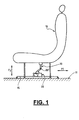
- FIG. 1 schematically represents a seat (10) of a motor vehicle, typically the driver or passenger seat before, a relay blower (20) placed under said seat (10), for example on the floor (11) of the vehicle, and a duct (30) for air circulation and connection sealed between the seat (10) and the blower (20).
- the seat (10) can move along rails (15) horizontally from front to back according to the arrow F1 and vertically from top to bottom according to the arrow F2.
- Headquarters (10) can for example move in a stroke of about ⁇ 100 mm in horizontal translation with respect to a median position, and about 100 mm from top to bottom between two extreme positions lowered and raised.
- the seat (10) is shown in the upper position.
- the connecting conduit (30) of the present invention is particularly suited to seat movements, combined or not, and to their ranges of movement, as explained below.
- the connecting duct (30) is made in two parts forming a Pantograph. More specifically, the conduit (30) is in the form a first and a second arm (32,34) hinged together about an axis of rotation XX 'substantially perpendicular to the movements of before in back and up and down the seat (10).
- the axis XX ' is substantially parallel to the floor (11) and perpendicular to the main direction of elongation of the duct (30) and each of its arms.
- the rotation range arms (32,34) between them is included, within a few degrees, between about 0 °, that is to say the two arms substantially in alignment, and about 180 °, that is to say the two arms folded against each other.
- a hinge (35) connects a first end (34a) of the second arm (34) and a second end (32b) of the first arm (32) for allow rotation of the arms between them about the axis XX ', as illustrated also in more detail in FIG. 6.
- This articulation (35) comprises, on its internal side, a thin waterproof film hinge (36) bound, for example by molding of material, with both arms (32,34).
- Lateral cheeks (38,39), represented in particular on the Figures 2 and 6 are also arranged perpendicularly to the hinge film (36) and the flexible plate (37), on the one hand to complete laterally the airtightness of the articulation (35), and also to guide in rotation the arms (32,34).
- circular grooves (40,42) are arranged in each side cheek.
- the circular grooves (40) receive the slice of the flexible plate (37) which moves in said grooves according to the angle of rotation between the arms.
- the circular grooves (42) each receive a guiding rail (44) projecting from both arm, as illustrated in particular in Figure 2.
- a first end (32a) of the first arm (32) of the duct (30) is airtightly connected to the blower (20) via a first junction box (50), as shown in FIGS. FIGS. 2 and 3.
- the first end (32a) is extended by a substantially half-cylindrical portion (32c) provided with molded sealing lips (32d), for example made of elastomer, as illustrated in FIG. Figure 5.
- These sealing lips (32d) cooperate with the inner wall of the first housing (50) which has a shape also substantially semicylindrical (52).
- the half-cylinder (32c) is provided with two lateral protuberances (32e) (see FIG. 2) cooperating with housings (51) of the first housing (50) to form an axis of rotation XX 1 substantially parallel to the axis of rotation XX 'of the joint (35).
- a second end (34b) of the second arm (34) of the duct (30) is airtightly connected to the seat (10) via a second connection box (53), as shown in FIGS. FIGS. 2 and 3.
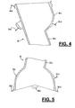
- the second end (34b) is extended by a substantially semi-cylindrical portion (34c) provided with molded sealing lips (34b), for example made of elastomer, as illustrated in FIG. Figure 4.
- These sealing lips (34d) cooperate with the inner wall of the second housing (53) which has a shape also substantially semicylindrical (54).
- the half-cylinder (34c) is also provided with two lateral protuberances (34e) (see FIG. 2) cooperating with housings (55) of the second housing (53) to form an axis of rotation XX 2 substantially parallel to the axis of rotation. rotation XX 'of the articulation (35).
- the duct (30) fits by rotation of the arms (32,34) of the duct (30) around the axis of rotation XX 'and their ends (32a, 34b) on the inside junction boxes (50,53).
- the conduit may comprise a number of arms greater than two, and therefore several joints, of the same type or different.
- the arms (32,34) can be articulated with each other and / or to the connecting boxes (50, 53) by a three-ball joint connection degrees of freedom in rotation. This is particularly suitable in the case where the seat is movable in three directions of movement, in particular according to three axes respectively perpendicular to each other (up-down, front-back and right-left).
- the two arms (32,34) are not necessarily in the extension of each other as shown in the mode of production. They can be parallel to each other but staggered along their common axis of rotation, that is to say one next to the other. So, it is possible to rotate them 360 ° to each other. For this, it is necessary to replace the elbow (35) by a connection for example under the form of two coaxial cylinders juxtaposed tightly bound to each other and standing axially from the first end (34a) of the second arm (34) and the second end (32b) of the first arm (32).
- the film hinge and the flexible plate can be linked with one other way than by molding a piece. They can for example be glued, overmolded, heat-sealed or clipped.
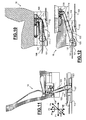
- the seat (10) is connected to a duct supplying air (101) according to a preferred example of construction of a main ventilation, heating and / or air conditioning via a conduit arranged in telescopic arm (102).
- This telescopic arm (102) comprises coaxial elements mounted successively sliding on one another, being equipped lip seal (103) for sealing the conduit (102).
- These coaxial elements include a medial element (104) and two elements end (105,106). These are respectively articulated on a first air-connecting element (107) assigned to the floor (108) of the vehicle, and on a second aeraulic connection element (109) assigned at the headquarters (10).
- the end elements (105,106) of the telescopic arm (102) are hinged to the aeraulic connection elements (107, 109), via bearings (110) that include these.
- the assembly of the end elements (105,106) on the bearings (110) is made by clipping their hinge pin (111) on these bearings (110), these hinge pins (111) being oriented orthogonally to the direction of longitudinal displacement F1 of the seat (10).
- a first movement direction F1 corresponds to a longitudinal mobility of the seat (10); a second direction of displacement F2, orthogonal to the previous F1, corresponds to a vertical mobility of the seat (10); a third direction of movement F3 corresponds to a pivoting the seat (10) on itself.
- the first and second directions of movement F1 and F2 are allowed from a deployment of the arm telescopic (102), while the third direction of displacement F3 is allowed from the pivoting elements (104,105,106) of the arm telescopic (102) relative to each other.
- the deformability of the arm telescopic (102) and its articulation on the connection elements a somehowlic (107,109) also allows a seat mobility (10) following a transverse displacement axis F4, orthogonal to the axes of displacement F1 and F2, and following a tilting axis F5 of the seat (10) relative to the vehicle floor (108).
- the aeraulic connection elements (107, 109) are shaped in a ball-and-socket shell which house the corresponding ends of the telescopic arm (102). These provisions are intended not to break the link aeraulic between these aeraulic connection elements (107,109) and the arm telescopic (102), regardless of the picked or deployed position of this last, and especially whatever its inclination to the floor (108) and relative to the seating of the seat (10).
- the first element of Aeraulic connection (107) is shaped as a housing having an outlet intake of air from the supply duct (101), and an outlet air outlet to the telescopic arm (102).
- This housing (107) comprises in in addition to an air outlet outlet to a foot ventilation duct rear (112), to constitute further and advantageously a housing of connection between the rear foot conduit (112) and the supply conduit (101).
- the second connection element (109) assigned to the seat (10) accommodates a secondary ventilation and heater.
- This secondary installation includes a relay pulsator (113) housed inside a basic compartment (114) of the second element of aeraulic connection (109).
- This basic compartment (114) is shaped in volute enveloping the relay blower (113).
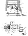
- the second air-flow connection element (109) Upstream of this compartment base (114), the second air-flow connection element (109) has a first compartment providing a mixing chamber (115), which has an outlet (116) for air intake from the external environment, and in particular of the passenger compartment of the vehicle.
- This mixing chamber (115) is provided with a particulate filter (117) and a electric heating element (118), especially CTP.
- This room mixer (115) is further arranged downstream of a second compartment (119) with which it communicates via a 120, such as a component.
- This second compartment (119) has a outlet of air from the main facility, and more directly from the telescopic arm (102).
- the mixing chamber (115) is overhanging second compartment (119) to avoid an undesirable increase in the size of the second air-flow connection element (109).
- the seat is connected to a supply duct of air (101) from a ventilation, heating and / or air conditioning via a conduit arranged in telescopic arm (121).
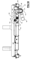
- the latter (121) is housed in the first connection element aunterlic, which is arranged in sheath (122) fixed to the guide rail (123) of the displacement in longitudinal translation F1 of the seat.
- the telescopic arm (121) is connected to the second air-flow connection element (124), which is itself attached to the seat via a reinforcing beam (125) that includes the latter.
- the sheath (122) comprises a receiving chamber (126) telescopic arm (121), which is extended by a chute (127) of guide.
- This chute (127) is provided with a protective cover (128), secured to the telescopic arm (121).
- the sleeve (122) advantageously forms a monobloc assembly with a connection box provided for the connection between the foot conduit (112) and the supply conduit (101).
- second connection element aunterlic (124) is organized in a similar way to that (109) of the variant embodiment shown in Fig.13 and Fig.14. More particularly, second aeraulic connection element (124) comprises a chamber of mixing (115) between the air coming from the main installation and the air in from the cockpit. This mixing chamber (115) is formed of a first compartment disposed upstream of the relay blower (not shown) and downstream of a second compartment (119) in connection with the arm telescopic (121).
- the type of seat equipped with the device of the The present invention is preferably used in a vehicle but it can for example adapt to a theater or conference, a cinema, an airplane or a boat.
Landscapes
- Engineering & Computer Science (AREA)
- Mechanical Engineering (AREA)
- Aviation & Aerospace Engineering (AREA)
- Transportation (AREA)
- Power Engineering (AREA)
- Physics & Mathematics (AREA)
- Thermal Sciences (AREA)
- Air-Conditioning For Vehicles (AREA)
- Chair Legs, Seat Parts, And Backrests (AREA)
- Seats For Vehicles (AREA)
- Duct Arrangements (AREA)
Abstract
Description
- les au moins deux bras sont articulés autour d'au moins un axe de rotation sensiblement perpendiculaire à deux directions de déplacement du siège ;
- le siège étant déplaçable respectivement selon deux directions sensiblement perpendiculaires l'une à l'autre, par exemple d'avant en arrière et de haut en bas, les deux bras du conduit sont articulés autour d'un axe de rotation perpendiculaire aux deux directions de déplacement du siège ;
- les deux bras sont articulés par une liaison pivot en forme de coude reliant une seconde extrémité du au moins premier bras et une première extrémité du au moins second bras ;
- l'une au moins desdites extrémités du premier bras et l'une au moins desdites extrémités du second bras se terminent chacune par une portion de cylindre ;
- les boítiers comportent également une portion de cylindre ;
- les portions de cylindre s'emboítent respectivement l'une dans l'autre ;
- les portions de cylindrent se juxtaposent de manière coaxiale l'une avec l'autre ;
- lequel les portions de cylindre comportent au moins une lèvre surmoulée qui assure une étanchéité à l'air à l'intérieur de chaque boítier de liaison ;
- la première extrémité du premier bras et la seconde extrémité du second bras se terminent chacune par une portion de sphère pour former une liaison rotule avec leur boítier correspondant ;
- ladite liaison entre les bras est munie d'une charnière film qui permet la rotation de manière étanche à l'air des bras entre eux ;
- la charnière film est moulée d'une pièce avec les deux bras ;
- une plaque souple est disposée de l'autre côté de la charnière film, pour former une articulation étanche à l'air des deux bras entre eux ;
- la plaque est moulée d'une pièce avec l'un des bras ;
- deux flancs latéraux sont en outre prévus de part et d'autre de la liaison entre les bras pour assurer et compléter l'étanchéité à l'air du conduit ;
- lesdits flancs sont munis de gorges externes et internes d'étanchéité et de guidage en rotation des bras articulés ;
- les gorges internes coopèrent avec des protubérances dont sont munis les bras au niveau du coude de liaison ;
- les gorges externes reçoivent la plaque souple ;
- les deux bras sont articulés entre eux par une liaison rotule ;
- la plage de rotation angulaire des bras entre eux est comprise entre 0° et au moins sensiblement 180°, et peut atteindre sensiblement 360° lorsqu'ils sont juxtaposés.
- la figure 1 une vue schématique d'un pulseur, d'un siège de véhicule automobile et d'un conduit de liaison pour les relier de manière étanche à l'air conformément à une première variante de réalisation de la présente invention,
- la figure 2, une vue en perspective détaillée du conduit de circulation d'air et de liaison de la figure 1,
- la figure 3, une vue en coupe dudit conduit de la fig.1 représenté dans deux positions différentes,
- la figure 4 une vue de détail d'une première extrémité du conduit représenté sur la fig.3,
- la figure 5, une vue de détail d'une seconde extrémité du conduit représenté sur la fig.3,
- la figure 6, une vue de détail d'une articulation du conduit représenté sur la fig.3,
- la figure 7, une vue similaire à la figure 1 dans laquelle le siège est en position avant,
- la figure 8, une vue similaire à la figure 1 dans laquelle le siège est en position arrière, et
- la figure 9, une vue similaire à la figure 1 dans laquelle le siège est en position baissée.
- les fig.10, fig.11 et fig.12, des illustrations en coupe d'un siège de véhicule automobile équipé d'un dispositif de jonction selon une deuxième variante de réalisation de la présente invention représentée selon trois positions de déplacement du siège, respectivement en position ramassée, en position de déploiement vertical , et en position de déploiement longitudinal,
- la fig.13, une vue arrière du dispositif de jonction représenté sur les fig.10, fig.11 et fig.12,
- la fig.14, un détail de la fig.13 illustrant une chambre de mixage ménagée à l'intérieur d'un élément de connexion aéraulique reliant le conduit au siège,
- la fig.15, un schéma partiel en perspective d'un dispositif de jonction selon une troisième variante de réalisation de la présente invention,
- la fig.16, une vue schématique partielle en coupe longitudinale du dispositif représenté sur la fig.15,
- la fig.17, une vue de dessus du dispositif représenté sur les fig.15 et fig.16,
- la fig.18, une vue schématique en coupe transversale du dispositif représenté sur la fig.17.
Claims (38)
- Dispositif de jonction entre un siège (10) et un conduit d'amenée (101) d'air, en provenance notamment d'une installation de ventilation, de chauffage et/ou de climatisation d'un véhicule, comprenant un conduit de liaison (30,102,121) entre le conduit d'amenée (101) et et le siège (10) , caractérisé en ce qu'il comprend au moins deux d'éléments de connexion aéraulique respectivement affectés au conduit d'amenée (101) pour un premier élément (50,107,122) et affecté au siège mobile (10) pour un deuxième élément (53,109,124), le conduit de liaison (30,102,121) étant un conduit à géométrie variable selon au moins un degré de liberté qui est monté à ses extrémités respectives sur les éléments de connexion aéraulique (50,107,122 ; 53,109,124) de sorte que la mobilité du siège (10) soit autorisée à partir d'au moins une jonction déformable entre les au moins deux éléments de connexion aéraulique qui sont respectivement solidaires du siège (10) et du conduit d'amenée (101).
- Dispositif selon la revendication 1, caractérisé en ce que l'un quelconque des éléments de connexion aéraulique (50,107,122 ; 53,109,124) est conformé en boítier.
- Dispositif selon la revendication 2, caractérisé en ce que l'un quelconque des éléments de connexion aéraulique (50,107,122 ;53,109,124) loge une organe relais de propulsion d'air (20,113).
- Dispositif selon l'une quelconque des revendications précédentes dans lequel le siège (10) est mobile selon au moins une direction de déplacement, caractérisé en ce que le conduit (20,102) est déformable suivant cette direction de déplacement du siège (10).
- Dispositif selon la revendication 4, dans lequel le siège est mobile suivant l'une quelconque au moins des directions comprenant une direction de déplacement longitudinale (F1), une direction verticale (F2) orthogonale à la précédente, une direction transversale (F4) orthogonale aux deux directions précédentes, une direction (F3) en pivotement du siège (10) sur lui-même, et une direction (F5) en basculement du siège (10) par rapport au plancher (108).
- Dispositif selon la revendication 1, caractérisé en ce qu'une chambre de mixage (115) est ménagée dans l'un quelconque des éléments de connexion aéraulique (50,107,122 ; 53,109,124), pour mélanger de l'air en provenance de l'habitacle avec l'air en provenance du conduit d'amenée (101).
- Dispositif selon la revendication 6, caractérisé en ce que la chambre de mixage (115) est équipée d'un organe (118) de chauffage secondaire de l'air en provenance de l'habitacle.
- Dispositif selon l'une quelconque des revendications 6 et 7, caractérisé en ce que le dit élément de connexion aéraulique (109,124) comporte un premier compartiment ménageant la chambre de mixage (115), qui est disposé en aval d'un deuxième compartiment (119) d'admission de l'air en provenance de l'installation principale, ces deux compartiments (115,119) étant séparés par un répartiteur (120).
- Dispositif selon l'une quelconque des revendications 6 à 8, caractérisé en ce que la chambre de mixage (115) est disposée en amont de l'organe de propulsion d'air (113).
- Dispositif selon l'une quelconque des revendications 6 à 8, caractérisé en ce que la chambre de mixage (115) est ménagée dans le deuxième élément de connexion (109,124).
- Dispositif selon la revendication 1, caractérisé en ce que le premier élément de connexion aéraulique (50,107,122) est conformé en boítier de liaison avec un conduit en provenance du conduit d'amenée (101).
- Dispositif selon la revendication 11, caractérisé en ce que le premier élément de connexion aéraulique (50,107,122) forme un ensemble monobloc avec un boítier de raccordement d'un conduit d'aération de pied arrière (112) avec le conduit d'amenée d'air (101).
- Dispositif selon l'une quelconque des revendications précédentes, caractérisé en ce que l'un quelconque des éléments de connexion aéraulique (50,107,122 ;53,109,124) est conformé en boítier ménageant la volute de l'organe de propulsion d'air (20,113).
- Dispositif selon l'une quelconque des revendications précédentes, caractérisé en ce que les éléments de connexion aéraulique (50,107 ;53,124) sont chacun conformés en boítier de liaison, sur lesquels boítiers est en prise articulée le conduit (30,102).
- Dispositif selon l'une quelconque des revendications précédentes, caractérisé en ce que le conduit est composé d'au moins deux bras (32,34 ; 104,105,106 ;121,126).
- Dispositif selon la revendication 15 caractérisé en ce qu'une première extrémité (32a) d'au moins un premier bras (32,105,121) du conduit (30) s'articule à l'intérieur d'un premier boítier de liaison (50,107,126) affecté au conduit d'amenée (101).
- Dispositif selon la revendication 15 caractérisé en ce que une seconde extrémité (34b) d'au moins un second bras (34,104,121) du conduit (30) s'articule à l'intérieur d'un second boítier (53,109,124) de liaison fixé au siège (10).
- Dispositif selon la revendication 16 ou 17, dans lequel la première extrémité (32a) du premier bras (34b) et la seconde extrémité (34b) du second bras (34) sont reliées respectivement de manière étanche à l'air à leur boítier correspondant (50 ; 53).
- Dispositif selon la revendication 15, dans lequel le conduit (30) forme un pantographe à au moins deux bras (32, 34) articulés à leur jonction.
- Dispositif selon la revendication 19, dans lequel les au moins deux bras sont articulés autour d'au moins un axe de rotation (XX') sensiblement perpendiculaire aux deux directions de déplacement du siège (10).
- Dispositif selon la revendication 20, dans lequel, le siège (10) étant déplaçable respectivement selon deux directions (F1 ;F2) sensiblement perpendiculaires l'une à l'autre, les deux bras (32, 34) du conduit (30) sont articulés autour d'un axe de rotation (XX') perpendiculaire aux deux directions de déplacement du siège.
- Dispositif selon l'une quelconque des revendications 15 à 21, dans lequel les deux bras (32, 34) sont articulés par une liaison pivot (35) en forme de coude reliant une seconde extrémité (32b) du au moins premier bras (32) et une première extrémité (34a) du au moins second bras (34).
- Dispositif selon l'une quelconque des revendications 15 à 22, dans lequel deux flancs latéraux (38, 39) sont en outre prévus de part et d'autre de la liaison entre les bras (32, 34) pour assurer et compléter l'étanchéité à l'air du conduit (30).
- Dispositif selon la revendication 23, dans lequel lesdits flancs sont munis de gorges externes et internes (40 , 42) d'étanchéité et de guidage en rotation des bras articulés (32, 34).
- Dispositif selon la revendication 15, dans lequel dans lequel les deux bras (32, 34) sont articulés par une liaison rotule au niveau d'un coude (35) reliant une seconde extrémité (32b) du au moins premier bras (32) et une première extrémité (34a) du au moins second bras.
- Dispositif selon la revendication 25, dans lequel la plage de rotation angulaire des bras (32, 34) entre eux est comprise entre 0° et au moins sensiblement 180°.
- Dispositif selon la revendication 26, dans lequel la plage de rotation angulaire des bras (32, 34) entre eux est sensiblement égale à 360°
- Dispositif selon l'une quelconque des revendications précédentes, caractérisé en ce que le siège (10) est un siège conducteur ou d'un passager avant d'un véhicule automobile.
- Dispositif selon la revendication 15, caractérisé en ce que le conduit est organisé en bras télescopique (102) à au moins deux éléments d'extrémités à axes parallèles (104,105,106), qui sont respectivement en prise articulée sur l'élément de connexion aéraulique correspondant (107,109).
- Dispositif selon la revendication 29, caractérisé en ce que le bras télescopique (102) comprend deux éléments d'extrémité (105,106) respectivement articulés sur les éléments de connexion aéraulique (109,107), et un élément médian (104).
- Dispositif selon l'une quelconque des revendications 29 et 30 caractérisé en ce que le bras télescopique (102) est mobile en rotation sur lui-même pour autoriser une rotation du siège (10) sur lui-même, et est mobile en pivotement sur les éléments de connexion aéraulique (109,107) autour d'axes de pivotement respectifs (111).
- Dispositif selon l'une quelconque des revendications 1 à 15, caractérisé en ce que le premier élément de connexion aéraulique (122) est agencé en fourreau de guidage en translation longitudinale du conduit agencé en bras télescopique (121).
- Dispositif selon la revendication 32, caractérisé en ce que le fourreau est fixé à un rail (123) de guidage du siège (10).
- Dispositif selon l'une quelconque des revendications 32 et 33, caractérisé en ce que le fourreau comporte une chambre (126) de réception du bras télescopique (121) pour sa mise en relation avec l'installation principale, cette chambre (126) étant prolongée par une goulotte (127) de guidage en translation du bras télescopique (121).
- Dispositif selon la revendication 34, caractérisé en ce que la goulotte (127) est munie d'un couvercle de protection (128).
- Dispositif selon la revendication 35, caractérisé en ce que le couvercle (128) est solidaire du bras télescopique (121).
- Dispositif selon l'une quelconque des revendications 33 à 36, caractérisé en ce que le bras télescopique (121) est muni de nervures de guidage radial à l'intérieur du fourreau (122).
- Dispositif selon l'une quelconque des revendications 1 à 15, caractérisé en ce que le conduit est organisé en conduit souple en prise à chacune de ses extrémités sur un élément de connexion aéraulique respectif.
Applications Claiming Priority (2)
| Application Number | Priority Date | Filing Date | Title |
|---|---|---|---|
| FR0307923 | 2003-06-30 | ||
| FR0307923A FR2856637B1 (fr) | 2003-06-30 | 2003-06-30 | Dispositif de ventilation, de chauffage et/ou de climatisation comprenant un organe de propulsion d'air, un siege et un conduit de liaison entre l'organe et le siege |
Publications (2)
| Publication Number | Publication Date |
|---|---|
| EP1493600A1 true EP1493600A1 (fr) | 2005-01-05 |
| EP1493600B1 EP1493600B1 (fr) | 2006-11-22 |
Family
ID=33427644
Family Applications (1)
| Application Number | Title | Priority Date | Filing Date |
|---|---|---|---|
| EP04015170A Expired - Lifetime EP1493600B1 (fr) | 2003-06-30 | 2004-06-29 | Dispositif de jonction entre une installation de ventilation, de chauffage et/ou de climatisation et un siège, d'un véhicule notamment |
Country Status (5)
| Country | Link |
|---|---|
| EP (1) | EP1493600B1 (fr) |
| AT (1) | ATE345943T1 (fr) |
| DE (1) | DE602004003298T2 (fr) |
| ES (1) | ES2275151T3 (fr) |
| FR (1) | FR2856637B1 (fr) |
Cited By (6)
| Publication number | Priority date | Publication date | Assignee | Title |
|---|---|---|---|---|
| EP1637370A3 (fr) * | 2004-09-21 | 2006-11-29 | Behr GmbH & Co. KG | Connection entre deux composants de transport d'air d'un système de ventilation, en particulier d'un système de ventilation de véhicule |
| FR2892976A1 (fr) * | 2005-11-04 | 2007-05-11 | Faurecia Interieur Ind Snc | Structure aeraulique pour aerateur, et procede de fabrication de planches de bord. |
| DE102007042055A1 (de) | 2007-09-05 | 2009-03-12 | Behr Gmbh & Co. Kg | Verbindungsvorrichtung zwischen einem stationären Luftkanal und einem in seiner Position veränderbaren Luftkanal |
| WO2015008474A1 (fr) * | 2013-07-17 | 2015-01-22 | 株式会社デンソー | Dispositif de climatisation pour siège de véhicule |
| US10023084B2 (en) | 2015-07-15 | 2018-07-17 | Gentherm Inc. | Vehicle seat with slidable air coupling |
| CN113165554A (zh) * | 2019-01-28 | 2021-07-23 | 宝马股份公司 | 具有调温装置的车辆座椅 |
Families Citing this family (1)
| Publication number | Priority date | Publication date | Assignee | Title |
|---|---|---|---|---|
| DE102019204958A1 (de) | 2019-04-08 | 2020-10-08 | Audi Ag | Klimatisierungsanordnung für ein Fahrzeug |
Citations (7)
| Publication number | Priority date | Publication date | Assignee | Title |
|---|---|---|---|---|
| US4840115A (en) * | 1987-05-04 | 1989-06-20 | Bayerische Motoren Werke Aktiengesellschaft | Air outlet arrangement of a heating and/or air-conditioning installation, especially for the rear space of a passenger motor vehicle |
| JPH09254642A (ja) * | 1996-03-25 | 1997-09-30 | Katsuhiro Takagaki | 自動車のシ−ト冷暖装置 |
| US5921100A (en) | 1997-06-03 | 1999-07-13 | Denso Corporation | Air conditioning apparatus for seat of vehicle |
| JP2000052747A (ja) * | 1998-08-04 | 2000-02-22 | Araco Corp | 温度調整機構付き車両用シート |
| US6059018A (en) | 1997-07-14 | 2000-05-09 | Denso Corporation | Vehicle seat air-conditioning system |
| US20010004008A1 (en) * | 1999-12-20 | 2001-06-21 | Shinji Aoki | Vehicle seat air conditioning system |
| US6478369B1 (en) | 1999-08-03 | 2002-11-12 | Denso Corporation | Seat air conditioner having mechanism following passenger seat |
Family Cites Families (1)
| Publication number | Priority date | Publication date | Assignee | Title |
|---|---|---|---|---|
| AUPN442895A0 (en) * | 1995-07-28 | 1995-08-17 | Ozone Manufacturing Pty Ltd | Flexible cantilevered hollow arm |
-
2003
- 2003-06-30 FR FR0307923A patent/FR2856637B1/fr not_active Expired - Fee Related
-
2004
- 2004-06-29 EP EP04015170A patent/EP1493600B1/fr not_active Expired - Lifetime
- 2004-06-29 AT AT04015170T patent/ATE345943T1/de not_active IP Right Cessation
- 2004-06-29 DE DE602004003298T patent/DE602004003298T2/de not_active Expired - Fee Related
- 2004-06-29 ES ES04015170T patent/ES2275151T3/es not_active Expired - Lifetime
Patent Citations (7)
| Publication number | Priority date | Publication date | Assignee | Title |
|---|---|---|---|---|
| US4840115A (en) * | 1987-05-04 | 1989-06-20 | Bayerische Motoren Werke Aktiengesellschaft | Air outlet arrangement of a heating and/or air-conditioning installation, especially for the rear space of a passenger motor vehicle |
| JPH09254642A (ja) * | 1996-03-25 | 1997-09-30 | Katsuhiro Takagaki | 自動車のシ−ト冷暖装置 |
| US5921100A (en) | 1997-06-03 | 1999-07-13 | Denso Corporation | Air conditioning apparatus for seat of vehicle |
| US6059018A (en) | 1997-07-14 | 2000-05-09 | Denso Corporation | Vehicle seat air-conditioning system |
| JP2000052747A (ja) * | 1998-08-04 | 2000-02-22 | Araco Corp | 温度調整機構付き車両用シート |
| US6478369B1 (en) | 1999-08-03 | 2002-11-12 | Denso Corporation | Seat air conditioner having mechanism following passenger seat |
| US20010004008A1 (en) * | 1999-12-20 | 2001-06-21 | Shinji Aoki | Vehicle seat air conditioning system |
Non-Patent Citations (2)
| Title |
|---|
| PATENT ABSTRACTS OF JAPAN vol. 1998, no. 01 30 January 1998 (1998-01-30) * |
| PATENT ABSTRACTS OF JAPAN vol. 2000, no. 05 14 September 2000 (2000-09-14) * |
Cited By (9)
| Publication number | Priority date | Publication date | Assignee | Title |
|---|---|---|---|---|
| EP1637370A3 (fr) * | 2004-09-21 | 2006-11-29 | Behr GmbH & Co. KG | Connection entre deux composants de transport d'air d'un système de ventilation, en particulier d'un système de ventilation de véhicule |
| FR2892976A1 (fr) * | 2005-11-04 | 2007-05-11 | Faurecia Interieur Ind Snc | Structure aeraulique pour aerateur, et procede de fabrication de planches de bord. |
| DE102007042055A1 (de) | 2007-09-05 | 2009-03-12 | Behr Gmbh & Co. Kg | Verbindungsvorrichtung zwischen einem stationären Luftkanal und einem in seiner Position veränderbaren Luftkanal |
| WO2015008474A1 (fr) * | 2013-07-17 | 2015-01-22 | 株式会社デンソー | Dispositif de climatisation pour siège de véhicule |
| US10471801B2 (en) | 2013-07-17 | 2019-11-12 | Denso Corporation | Air-conditioning device for vehicle seat |
| US10023084B2 (en) | 2015-07-15 | 2018-07-17 | Gentherm Inc. | Vehicle seat with slidable air coupling |
| US10286817B2 (en) | 2015-07-15 | 2019-05-14 | Gentherm Inc. | Vehicle seat with slidable air coupling |
| CN113165554A (zh) * | 2019-01-28 | 2021-07-23 | 宝马股份公司 | 具有调温装置的车辆座椅 |
| US11845368B2 (en) | 2019-01-28 | 2023-12-19 | Bayerische Motoren Werke Aktiengesellschaft | Vehicle seat comprising a temperature-control system |
Also Published As
| Publication number | Publication date |
|---|---|
| FR2856637A1 (fr) | 2004-12-31 |
| FR2856637B1 (fr) | 2008-02-15 |
| EP1493600B1 (fr) | 2006-11-22 |
| ATE345943T1 (de) | 2006-12-15 |
| DE602004003298D1 (de) | 2007-01-04 |
| ES2275151T3 (es) | 2007-06-01 |
| DE602004003298T2 (de) | 2007-06-21 |
Similar Documents
| Publication | Publication Date | Title |
|---|---|---|
| EP1814752B1 (fr) | Aerateur de systeme de ventilation de l'habitacle d'un vehicule | |
| EP3539819A1 (fr) | Accoudoir pour siège de véhicule et siege de vehicule comportant un tel accoudoir | |
| FR2960829A1 (fr) | Dispositif de sortie d'air pour vehicule automobile comprenant un deflecteur | |
| EP3847047B1 (fr) | Dispositif de regulation d'un flux d'air pour une entree d'air d'un vehicule automobile | |
| EP1493600B1 (fr) | Dispositif de jonction entre une installation de ventilation, de chauffage et/ou de climatisation et un siège, d'un véhicule notamment | |
| EP2505397B1 (fr) | Dispositif de sortie d'air comprenant un matériau d'étancheité | |
| FR2720693A1 (fr) | Dispositif de chauffage et/ou d'aération de l'habitacle d'un véhicule. | |
| FR3062087A1 (fr) | Aerateur, notamment pour vehicule automobile | |
| FR2620293A1 (fr) | Enceinte accoustique tetiere pour automobile | |
| EP3576971B1 (fr) | Dispositif de régulation d'un flux d'air circulant sous le capot d'un véhicule | |
| FR2773111A1 (fr) | Dispositif de chauffage et/ou climatisation a mixage d'air pour vehicule automobile | |
| FR2479106A1 (fr) | Dispositif de chauffage et d'aeration pour vehicule automobile | |
| EP2814678B1 (fr) | Installation de chauffage, ventilation et/ou climatisation pour un habitacle de véhicule automobile | |
| FR2688451A1 (fr) | Buse d'air guide pour le degivrage de la vitre laterale et l'aeration de l'habitacle d'un vehicule. | |
| FR2878469A1 (fr) | Dispositif de repartition de flux d'air, notamment pour un appareil de chauffage, ventilation et/ou climatisation d'un habitacle de vehicule automobile | |
| WO2002102614A1 (fr) | Installation de chauffage et/ou de climatisation munie de volets mobiles pour habitacle de vehicule automobile, et vehicule equipe d'une telle installation | |
| FR2833530A1 (fr) | Appareil de chauffage et/ou de climatisation a organe de mixage et de repartition d'air pour habitacle de vehicule automobile | |
| EP0940294B1 (fr) | Dispositif d'étanchéité pour rétroviseur extérieur, en particulier de véhicule automobile | |
| EP1197365B1 (fr) | Dispositif de distribution et d'orientation d'air, notamment pour automobile | |
| FR3080809A1 (fr) | Siege de vehicule | |
| FR2910384A1 (fr) | Dispositif d'aeration a volet mobile et clapet pour l'habitacle d'un vehicule automobile | |
| WO2019096758A1 (fr) | Vehicule comportant une console centrale dotee d'un rangement arriere | |
| EP2011692A1 (fr) | Boîtier de rangement pour véhicule automobile | |
| EP3315335A1 (fr) | Dispositif de climatisation/chauffage de véhicule | |
| FR2760699A1 (fr) | Vehicule automobile a siege fixe et tablette arriere |
Legal Events
| Date | Code | Title | Description |
|---|---|---|---|
| PUAI | Public reference made under article 153(3) epc to a published international application that has entered the european phase |
Free format text: ORIGINAL CODE: 0009012 |
|
| AK | Designated contracting states |
Kind code of ref document: A1 Designated state(s): AT BE BG CH CY CZ DE DK EE ES FI FR GB GR HU IE IT LI LU MC NL PL PT RO SE SI SK TR |
|
| AX | Request for extension of the european patent |
Extension state: AL HR LT LV MK |
|
| 17P | Request for examination filed |
Effective date: 20050524 |
|
| AKX | Designation fees paid |
Designated state(s): AT BE BG CH CY CZ DE DK EE ES FI FR GB GR HU IE IT LI LU MC NL PL PT RO SE SI SK TR |
|
| RAP1 | Party data changed (applicant data changed or rights of an application transferred) |
Owner name: VALEO SYSTEMES THERMIQUES |
|
| GRAP | Despatch of communication of intention to grant a patent |
Free format text: ORIGINAL CODE: EPIDOSNIGR1 |
|
| GRAS | Grant fee paid |
Free format text: ORIGINAL CODE: EPIDOSNIGR3 |
|
| GRAA | (expected) grant |
Free format text: ORIGINAL CODE: 0009210 |
|
| AK | Designated contracting states |
Kind code of ref document: B1 Designated state(s): AT BE BG CH CY CZ DE DK EE ES FI FR GB GR HU IE IT LI LU MC NL PL PT RO SE SI SK TR |
|
| PG25 | Lapsed in a contracting state [announced via postgrant information from national office to epo] |
Ref country code: RO Free format text: LAPSE BECAUSE OF FAILURE TO SUBMIT A TRANSLATION OF THE DESCRIPTION OR TO PAY THE FEE WITHIN THE PRESCRIBED TIME-LIMIT Effective date: 20061122 Ref country code: NL Free format text: LAPSE BECAUSE OF FAILURE TO SUBMIT A TRANSLATION OF THE DESCRIPTION OR TO PAY THE FEE WITHIN THE PRESCRIBED TIME-LIMIT Effective date: 20061122 Ref country code: PL Free format text: LAPSE BECAUSE OF FAILURE TO SUBMIT A TRANSLATION OF THE DESCRIPTION OR TO PAY THE FEE WITHIN THE PRESCRIBED TIME-LIMIT Effective date: 20061122 Ref country code: SK Free format text: LAPSE BECAUSE OF FAILURE TO SUBMIT A TRANSLATION OF THE DESCRIPTION OR TO PAY THE FEE WITHIN THE PRESCRIBED TIME-LIMIT Effective date: 20061122 Ref country code: IE Free format text: LAPSE BECAUSE OF FAILURE TO SUBMIT A TRANSLATION OF THE DESCRIPTION OR TO PAY THE FEE WITHIN THE PRESCRIBED TIME-LIMIT Effective date: 20061122 Ref country code: FI Free format text: LAPSE BECAUSE OF FAILURE TO SUBMIT A TRANSLATION OF THE DESCRIPTION OR TO PAY THE FEE WITHIN THE PRESCRIBED TIME-LIMIT Effective date: 20061122 Ref country code: SI Free format text: LAPSE BECAUSE OF FAILURE TO SUBMIT A TRANSLATION OF THE DESCRIPTION OR TO PAY THE FEE WITHIN THE PRESCRIBED TIME-LIMIT Effective date: 20061122 Ref country code: AT Free format text: LAPSE BECAUSE OF FAILURE TO SUBMIT A TRANSLATION OF THE DESCRIPTION OR TO PAY THE FEE WITHIN THE PRESCRIBED TIME-LIMIT Effective date: 20061122 |
|
| REG | Reference to a national code |
Ref country code: GB Ref legal event code: FG4D Free format text: NOT ENGLISH |
|
| RTI1 | Title (correction) |
Free format text: CONNECTION DEVICE BETWEEN A VEHICLE SEAT AND THE VENTILATION AND/OR HEATING AND/OR CONDITIONING SYSTEM |
|
| REG | Reference to a national code |
Ref country code: CH Ref legal event code: EP |
|
| REG | Reference to a national code |
Ref country code: IE Ref legal event code: FG4D Free format text: LANGUAGE OF EP DOCUMENT: FRENCH |
|
| REF | Corresponds to: |
Ref document number: 602004003298 Country of ref document: DE Date of ref document: 20070104 Kind code of ref document: P |
|
| PG25 | Lapsed in a contracting state [announced via postgrant information from national office to epo] |
Ref country code: BG Free format text: LAPSE BECAUSE OF FAILURE TO SUBMIT A TRANSLATION OF THE DESCRIPTION OR TO PAY THE FEE WITHIN THE PRESCRIBED TIME-LIMIT Effective date: 20070222 Ref country code: DK Free format text: LAPSE BECAUSE OF FAILURE TO SUBMIT A TRANSLATION OF THE DESCRIPTION OR TO PAY THE FEE WITHIN THE PRESCRIBED TIME-LIMIT Effective date: 20070222 Ref country code: SE Free format text: LAPSE BECAUSE OF FAILURE TO SUBMIT A TRANSLATION OF THE DESCRIPTION OR TO PAY THE FEE WITHIN THE PRESCRIBED TIME-LIMIT Effective date: 20070222 |
|
| PG25 | Lapsed in a contracting state [announced via postgrant information from national office to epo] |
Ref country code: PT Free format text: LAPSE BECAUSE OF FAILURE TO SUBMIT A TRANSLATION OF THE DESCRIPTION OR TO PAY THE FEE WITHIN THE PRESCRIBED TIME-LIMIT Effective date: 20070423 |
|
| NLV1 | Nl: lapsed or annulled due to failure to fulfill the requirements of art. 29p and 29m of the patents act | ||
| REG | Reference to a national code |
Ref country code: ES Ref legal event code: FG2A Ref document number: 2275151 Country of ref document: ES Kind code of ref document: T3 |
|
| GBV | Gb: ep patent (uk) treated as always having been void in accordance with gb section 77(7)/1977 [no translation filed] |
Effective date: 20061122 |
|
| REG | Reference to a national code |
Ref country code: IE Ref legal event code: FD4D |
|
| PLBE | No opposition filed within time limit |
Free format text: ORIGINAL CODE: 0009261 |
|
| STAA | Information on the status of an ep patent application or granted ep patent |
Free format text: STATUS: NO OPPOSITION FILED WITHIN TIME LIMIT |
|
| 26N | No opposition filed |
Effective date: 20070823 |
|
| PG25 | Lapsed in a contracting state [announced via postgrant information from national office to epo] |
Ref country code: GB Free format text: LAPSE BECAUSE OF FAILURE TO SUBMIT A TRANSLATION OF THE DESCRIPTION OR TO PAY THE FEE WITHIN THE PRESCRIBED TIME-LIMIT Effective date: 20061122 |
|
| BERE | Be: lapsed |
Owner name: VALEO SYSTEMES THERMIQUES Effective date: 20070630 |
|
| PG25 | Lapsed in a contracting state [announced via postgrant information from national office to epo] |
Ref country code: MC Free format text: LAPSE BECAUSE OF NON-PAYMENT OF DUE FEES Effective date: 20070630 |
|
| PG25 | Lapsed in a contracting state [announced via postgrant information from national office to epo] |
Ref country code: BE Free format text: LAPSE BECAUSE OF NON-PAYMENT OF DUE FEES Effective date: 20070630 |
|
| PG25 | Lapsed in a contracting state [announced via postgrant information from national office to epo] |
Ref country code: GR Free format text: LAPSE BECAUSE OF FAILURE TO SUBMIT A TRANSLATION OF THE DESCRIPTION OR TO PAY THE FEE WITHIN THE PRESCRIBED TIME-LIMIT Effective date: 20070223 |
|
| PGFP | Annual fee paid to national office [announced via postgrant information from national office to epo] |
Ref country code: CZ Payment date: 20080602 Year of fee payment: 5 Ref country code: ES Payment date: 20080620 Year of fee payment: 5 |
|
| PGFP | Annual fee paid to national office [announced via postgrant information from national office to epo] |
Ref country code: IT Payment date: 20080621 Year of fee payment: 5 |
|
| PGFP | Annual fee paid to national office [announced via postgrant information from national office to epo] |
Ref country code: DE Payment date: 20080613 Year of fee payment: 5 |
|
| PGFP | Annual fee paid to national office [announced via postgrant information from national office to epo] |
Ref country code: FR Payment date: 20080630 Year of fee payment: 5 |
|
| PG25 | Lapsed in a contracting state [announced via postgrant information from national office to epo] |
Ref country code: EE Free format text: LAPSE BECAUSE OF FAILURE TO SUBMIT A TRANSLATION OF THE DESCRIPTION OR TO PAY THE FEE WITHIN THE PRESCRIBED TIME-LIMIT Effective date: 20061122 |
|
| REG | Reference to a national code |
Ref country code: CH Ref legal event code: PL |
|
| PG25 | Lapsed in a contracting state [announced via postgrant information from national office to epo] |
Ref country code: LI Free format text: LAPSE BECAUSE OF NON-PAYMENT OF DUE FEES Effective date: 20080630 Ref country code: CH Free format text: LAPSE BECAUSE OF NON-PAYMENT OF DUE FEES Effective date: 20080630 |
|
| PG25 | Lapsed in a contracting state [announced via postgrant information from national office to epo] |
Ref country code: CY Free format text: LAPSE BECAUSE OF FAILURE TO SUBMIT A TRANSLATION OF THE DESCRIPTION OR TO PAY THE FEE WITHIN THE PRESCRIBED TIME-LIMIT Effective date: 20061122 Ref country code: LU Free format text: LAPSE BECAUSE OF NON-PAYMENT OF DUE FEES Effective date: 20070629 |
|
| PG25 | Lapsed in a contracting state [announced via postgrant information from national office to epo] |
Ref country code: TR Free format text: LAPSE BECAUSE OF FAILURE TO SUBMIT A TRANSLATION OF THE DESCRIPTION OR TO PAY THE FEE WITHIN THE PRESCRIBED TIME-LIMIT Effective date: 20061122 Ref country code: HU Free format text: LAPSE BECAUSE OF FAILURE TO SUBMIT A TRANSLATION OF THE DESCRIPTION OR TO PAY THE FEE WITHIN THE PRESCRIBED TIME-LIMIT Effective date: 20070523 |
|
| PG25 | Lapsed in a contracting state [announced via postgrant information from national office to epo] |
Ref country code: CZ Free format text: LAPSE BECAUSE OF NON-PAYMENT OF DUE FEES Effective date: 20090629 |
|
| REG | Reference to a national code |
Ref country code: FR Ref legal event code: ST Effective date: 20100226 |
|
| PG25 | Lapsed in a contracting state [announced via postgrant information from national office to epo] |
Ref country code: FR Free format text: LAPSE BECAUSE OF NON-PAYMENT OF DUE FEES Effective date: 20090630 |
|
| PG25 | Lapsed in a contracting state [announced via postgrant information from national office to epo] |
Ref country code: DE Free format text: LAPSE BECAUSE OF NON-PAYMENT OF DUE FEES Effective date: 20100101 |
|
| REG | Reference to a national code |
Ref country code: ES Ref legal event code: FD2A Effective date: 20090630 |
|
| PG25 | Lapsed in a contracting state [announced via postgrant information from national office to epo] |
Ref country code: ES Free format text: LAPSE BECAUSE OF NON-PAYMENT OF DUE FEES Effective date: 20090630 |
|
| PG25 | Lapsed in a contracting state [announced via postgrant information from national office to epo] |
Ref country code: IT Free format text: LAPSE BECAUSE OF NON-PAYMENT OF DUE FEES Effective date: 20090629 |