EP1493321B1 - Heuwerbungsmaschine - Google Patents
Heuwerbungsmaschine Download PDFInfo
- Publication number
- EP1493321B1 EP1493321B1 EP04014297A EP04014297A EP1493321B1 EP 1493321 B1 EP1493321 B1 EP 1493321B1 EP 04014297 A EP04014297 A EP 04014297A EP 04014297 A EP04014297 A EP 04014297A EP 1493321 B1 EP1493321 B1 EP 1493321B1
- Authority
- EP
- European Patent Office
- Prior art keywords
- machine
- rotary rakes
- travel
- working
- haymaking machine
- Prior art date
- Legal status (The legal status is an assumption and is not a legal conclusion. Google has not performed a legal analysis and makes no representation as to the accuracy of the status listed.)
- Not-in-force
Links
Images


Classifications
-
- A—HUMAN NECESSITIES
- A01—AGRICULTURE; FORESTRY; ANIMAL HUSBANDRY; HUNTING; TRAPPING; FISHING
- A01D—HARVESTING; MOWING
- A01D78/00—Haymakers with tines moving with respect to the machine
- A01D78/08—Haymakers with tines moving with respect to the machine with tine-carrying rotary heads or wheels
- A01D78/10—Haymakers with tines moving with respect to the machine with tine-carrying rotary heads or wheels the tines rotating about a substantially vertical axis
- A01D78/1092—Having more than two rows of rotors on more than two different horizontal lines perpendicular to the advance direction of the machine
Definitions
- the invention relates to a haymaking machine, in particular for swathing agricultural stalk material with four circumferentially driven, supportable via support wheels on the ground and via boom from a working and operating position into a tilted transport position convertible rotary rake in the direction of travel substantially V-shaped arrangement.
- a haymaking machine of the aforementioned type is for example from the DE 197 16 379 C1 known.
- four rotary rakes are provided, each two associated rotary rakes are arranged one behind the other in the direction of travel.
- the two rotary rakes upstream in the direction of travel determine the maximum working width and are located in front of an unsteered machine axis.
- the respective rotary rakes are to be pivoted inwards.
- the maximum working width is significantly increased in this haymaking machine compared to a haymaking machine with only two rotary rakes, but the desire for even larger working widths is not fair, although in the transport position of the parts, the limits of maximum transport height are already reached.
- the EP 1 433 372 A1 shows a haymaking machine, in particular for swathing agricultural stalk with four circumferentially driven and over Support wheels on the ground supportable, as well as over boom from a working and operating position in a tilted transport position convertible rotary rake, which are aligned in the working and operating position in the direction of travel substantially V-shaped and those in the working and operating position in the direction of travel at least two further, the maximum working width determining rotary rakes are upstream.
- this is a document under Article 54 (3) EPC.
- the haymaking machine of the type mentioned is characterized in that the rotary rake in the working and operating position in the direction of travel at least two more, the maximum working width determining rotary rakes are arranged upstream and that the distance dimension of the vertical longitudinal axes of two in the direction of travel behind each other, and an unguided, provided with wheels machine axis upstream rotary rake is less than the distance dimension of the vertical longitudinal center axes of the two adjacent in the direction of travel rotary rakes.
- the rotary rake in the working and operating position in the direction of travel at least two more, the maximum working width determining rotary rakes are arranged upstream and that the distance between the vertical longitudinal axes of middle and rear and an unsteered machine axis downstream rotary rake smaller or is equal to a distance measure of the vertical longitudinal axes of the front and middle, adjacent in the direction of travel rotary rake.
- a further solution to this problem provides that the rotary rake in the working and operating position driving direction at least two more, the maximum working width determining rotary rakes are arranged upstream and that the shortest distance C between another rotary rake and the adjacent rotary rake 10% to 50% of the diameter D is the further rotary counter.
- the other rotary rakes are provided so that - depending on which of the intended machine axes is steered or unguided - the respective distance dimension of the vertical longitudinal axes of the two in the machine direction respectively adjacent rotary rake, either the unguided axle upstream or downstream of the steered axle are less than the distance dimension of the vertical longitudinal axes of the other adjacent in the direction of travel rotary rake.
- the distance of the vertical longitudinal axes of these two in the machine direction of the unguided machine axis upstream rotary rake is less than the distance measure of the other two rotary rake.
- the position of the rotary rakes to the instantaneous pole of the machine is provided taking into account the Lenklaufeigenschaften such that due to the associated overlap or overlap areas of the effective processing areas of the rotary rake an effective and clean hay advertising result is even when cornering.
- This advantageous hay advertising result can also be achieved if the additional rotary rake reaches as far as the downstream rotary rake, depending on its diameter, such that the shortest distance dimension is 0.1 to 0.5 of the diameter of the further rotary rake.
- the haymaking machine according to the invention is preferably designed as a self-propelled haymaking machine with its own driver's cab and its own motor drive, wherein the two outer and thus the two other rotary rakes of the driver's cab are directly in front or sibling.
- the two other rotary rakes - based on the connection of their respective boom - offset on the machine frame in the direction of travel backwards, so that they are located approximately next to the driver's cab and thus can work within sight of the driver, without this has to perform special elaborate movements.
- the self-propelled machine is provided with a front steered machine axis, so that the distance dimension of the vertical longitudinal axes of the respective adjacent in the direction of travel rotary rakes of the two front in the direction of rotary rake pairs is less than the distance of the vertical longitudinal axes of the respective rotary rakes of the middle rotary rake pair and the rear rotary pair of rotors in the direction of travel.
- the haymaking machine according to the invention can also be designed as a drawn haymaking machine with suitably an unguided machine axis between the middle rotary rake pair and the rear in the direction of rotary rake pair, with respect to the distance of the vertical longitudinal axes of the rotary rake of the two front in the direction of travel rake pairs analogous results as in the previously described self-propelled haymaking machine.
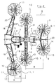
- a haymaking machine is generally denoted by 1, which is formed in the embodiments of FIGS. 1 to 5 as a self-propelled haymaking machine and in the embodiments of FIGS. 6 to 8 as hauled by an agricultural tractor 2 haymaking machine.
- the self-propelled haymaking machine shown in Figs. 1 to 5 has a vehicle chassis 3, wheels 4 and a cab 5 and - which in detail closer from the illustration of FIG. 2 shows - a working direction 6.
- In the embodiment shown are in the direction of travel. 6 front wheels 4 on a steered machine axis 7 and arranged in the direction of travel rear wheels 4 on a non-steered machine axis 8.
- V-shaped arrangement rear rotary rake 9 and this rotary rake 9 upstream rotary rake 10 are provided in the direction of travel.
- the rotary rake 10 are preceded by two more rotary rakes 11 in the direction of travel 6, so that a total of one machine with a total of three rotary rake pairs with six rotary rakes 9, 10, 11 results.
- the rotary rakes 9, 10, 11 are structurally coordinated in a special way or adapted to each other.
- the front in the direction of travel and thus further rotary rake 11 are provided with a rearwardly offset in the direction of travel 6 distance in the working and operating position, so that the distance A of the vertical longitudinal center axis 12 of the front further gyro 11 to the vertical longitudinal center axis 13 of the adjacent in the direction of travel Rotary counter 10 is smaller than the distance of the vertical longitudinal central axis 13 of this rotary rake 10 to the vertical longitudinal central axis 14 of the downstream in the direction of rotary rake 9.
- the distance between the vertical longitudinal center axes 13 and 14 of these two adjacent rotary rakes 10 and 9 is designated B.
- These distance measurements relate to a haymaking machine with the illustrated arrangement of steered and unguided machine axis. However, if the machine axis steered in the embodiment according to FIGS. 1 to 5, the machine axis, the rear in the direction of travel, so that the front in the direction of travel 6 axis is an unguided axis, the distance B would be smaller than the distance measure A. In compliance with this In the case of a haymaking machine with six rotary rakes and the enormous working width, the parameter is an optimum swath result even when cornering.
- the rotary rake 11 is attached to the downstream rotary rake 10 in such a way that the shortest distance dimension is 0.1 to 0.5 of the diameter D of the further rotary rake.
- the rotary rakes 9, 10, and 11 are in turn supported on support wheels 15, 16 and 17 in the working position on the ground.
- the boom 18 of the respective other (front) gyro 11 is on more wheels 19 in the working position can be supported on the ground.
- these arms 18 are hinged to the machine so that they point at an acute angle to the machine longitudinal axis 20 in the working position.
- This boom 18, as well as the boom 21 and 22 of the other gyros 9 and 10 are pivotally hinged to the machine frame 3 and can be converted into the from Fig. 4 and Fig. 5 apparent folded and inwardly tilted transport position.
- the front boom consists of two parts and each has an Endstützarm 23 which has an angled dome-like shape (see Fig. 1), so that it is to pivot relative to the other region of the boom 18 inwardly, with the advantage that the rotary rake 12 can still be pivoted in the transport position in the provided by the dome-like design inner pivoting.
- the haymaking machine is designed as a machine pulled by an agricultural tractor 2. It is there to connect to the usual three-point hydraulic system 25 of the tractor 2 via a machine frame 26 which is supported on wheels 27 of a non-steered machine axis 28 on the ground.
- the numbered with 9.10 and 11 rotary rakes are in turn supported by wheels 15, 16 and 17 on the ground and have rake tines 11.1, 10.1 and 9.1, which rotate about the vertical longitudinal central axes 12, 13 and 14 respectively.
- the distance dimension of the respective longitudinal central axes 12 and 13 of the two in the direction 6 of the unguided axle 28 upstream rotary rakes 10 and 11 is smaller than the distance B of the vertical longitudinal axes 13 and 14 of the other two rotary rakes 9 and 10.
- the rotary rakes in turn are inward and supported outwardly pivotally supported arms 29 which are fixed to the support frame 26.
- the boom 29 and movable pivotable on the machine frame actuating means 30 the boom 29 can be pivoted inwardly together with the rotary rake, as shown in FIG. 7.
- the rotary rakes are swiveled up into a transport position with outwardly pointing rake tines 11.1, 10.1 and 9.1, as FIG. 8 illustrates. It can be seen that the transport width of the haymaking machine is only slightly larger than the width of the agricultural tractor.
Landscapes
- Life Sciences & Earth Sciences (AREA)
- Environmental Sciences (AREA)
- Soil Working Implements (AREA)
- Harvester Elements (AREA)
- Agricultural Machines (AREA)
- Guiding Agricultural Machines (AREA)
- Control Of Multiple Motors (AREA)
- Glass Compositions (AREA)
- Paper (AREA)
- Processes Of Treating Macromolecular Substances (AREA)
- Separation By Low-Temperature Treatments (AREA)
- Compounds Of Unknown Constitution (AREA)
Description
- Die Erfindung bezieht sich auf eine Heuwerbungsmaschine, insbesondere zum Schwaden von landwirtschaftlichem Halmgut mit vier umlaufend angetriebenen, über Stützräder auf dem Erdboden abstützbaren sowie über Ausleger aus einer Arbeits- und Betriebsstellung in eine verschwenkte Transportstellung überführbaren Kreiselrechen in in Fahrtrichtung im wesentlichen V-förmiger Anordnung.
- Eine Heuwerbungsmaschine der vorgenannten Art ist beispielsweise aus der
DE 197 16 379 C1 bekannt. Bei dieser Maschine sind vier Kreiselrechen vorgesehen, wobei jeweils zwei einander zugeordnete Kreiselrechen in Fahrtrichtung hintereinander angeordnet sind. Die beiden in Fahrtrichtung vorgeordneten Kreiselrechen bestimmen die maximale Arbeitsbreite und sind vor einer ungelenkten Maschinenachse gelegen. Zur Überführung in ihre Transportstellung sind die jeweiligen Kreiselrechen einwärts zu verschwenken. Die maximal mögliche Arbeitsbreite ist bei dieser Heuwerbungsmaschine gegenüber einer Heuwerbungsmaschine mit lediglich zwei Kreiselrechen deutlich erhöht, wird jedoch dem Wunsch nach noch größeren Arbeitsbreiten noch nicht gerecht, obgleich in der Transportstellung der Teile die Grenzen einer maximalen Transporthöhe schon erreicht sind. - Die
EP 1 433 372 A1 zeigt eine Heuwerbungsmaschine, insbesondere zum Schwaden von landwirtschaftlichem Halmgut mit vier umlaufend angetriebenen und über Stützräder auf dem Erdboden abstützbaren, sowie über Ausleger aus einer Arbeits- und Betriebsstellung in eine verschwenkte Transportstellung überführbaren Kreiselrechen, die in der Arbeits- und Betriebsstellung in Fahrtrichtung im wesentlichen V-förmig ausgerichtet sind und denen in der Arbeits- und Betriebsstellung in Fahrtrichtung zumindest zwei weitere, die maximale Arbeitsbreite bestimmende Kreiselrechen vorgeordnet sind. Hierbei handelt es sich allerdings um ein Dokument nach Artikel 54(3) EPÜ. - Es ist daher Aufgabe der vorliegenden Erfindung, eine Heuwerbungsmaschine der eingangs genannten Art zu schaffen, mit der die wirksame Gesamtarbeitsbreite noch weiter zu erhöhen ist, bei der aber gleichwohl auch bei Kurvenfahrten noch ein sauberes Heuwerbungsergebnis, insbesondere auch ein exaktes Schwadlegen von Halmgut möglich ist.
- Zur Lösung dieser Aufgabe zeichnet sich die Heuwerbungsmaschine der eingangs genannten Art dadurch aus, dass den Kreiselrechen in der Arbeits- und Betriebsstellung in Fahrtrichtung zumindest zwei weitere, die maximale Arbeitsbreite bestimmende Kreiselrechen vorgeordnet sind und dass das Abstandsmaß der Vertikallängsmittelachsen von zwei in Fahrtrichtung hintereinander angeordneten, sowie einer ungelenkten, mit Laufrädern versehenen Maschinenachse vorgeordneten Kreiselrechen geringer ist als das Abstandsmaß der vertikalen Längsmittelachsen der zwei in Fahrtrichtung benachbarten Kreiselrechen. Gemäß dem zweiten Anspruch ist aber auch denkbar, dass den Kreiselrechen in der Arbeits- und Betriebsstellung in Fahrtrichtung zumindest zwei weitere, die maximale Arbeitsbreite bestimmende Kreiselrechen vorgeordnet sind und dass das Abstandsmaß zwischen den Vertikallängsmittelachsen von mittleren und hinteren und einer ungelenkten Maschinenachse nachgeordneten Kreiselrechen kleiner oder gleich einem Abstandsmaß der Vertikallängsmittelachsen der vorderen und mittleren, in Fahrtrichtung benachbart angeordneten Kreiselrechen ist. Eine weitere Lösung dieser Aufgabe sieht vor, dass den Kreiselrechen in der Arbeits- und Betriebsstellung Fahrtrichtung zumindest zwei weitere, die maximale Arbeitsbreite bestimmende Kreiselrechen vorgeordnet sind und dass das kürzeste Abstandsmaß C zwischen einem weiteren Kreiselrechen und dem benachbarten Kreiselrechen 10 % bis 50 % des Durchmessers D des weiteren Kreiselrechens beträgt.
- Damit ist eine Heuwerbungsmaschine zur Verfügung gestellt, bei der die wirksame Gesamtarbeitsbreite noch weiter erhöht ist, so dass Arbeitsbreiten von z. B. 20 Metern durchaus realisierbar sind. Um bei solch großen Arbeitsbreiten auch noch ein befriedigendes Heuwerbungsergebnis zu erzielen, sind die weiteren Kreiselrechen derart vorgesehen, dass - je nachdem, welche der vorgesehenen Maschinenachsen gelenkt oder ungelenkt ist - das jeweilige Abstandsmaß der Vertikallängsmittelachsen der beiden in Maschinenfahrtrichtung jeweils benachbarten Kreiselrechen, die entweder der ungelenkten Achse vor- oder der ungelenkten Achse nachgeordnet sind, geringer ist als das Abstandsmaß der Vertikallängsmittelachsen der anderen in Fahrtrichtung benachbarten Kreiselrechen. Ist beispielsweise in Maschinenfahrtrichtung ein Kreiselrechenpaar einer ungelenkten Maschinenachse nachgeordnet und die beiden anderen Kreiselrechenpaare dieser ungelenkten Maschinenachse vorgeordnet, so ist das Abstandsmaß der Vertikallängsmittelachsen dieser beiden in Maschinenfahrtrichtung der ungelenkten Maschinenachse vorgeordneten Kreiselrechen geringer als das Abstandsmaß der beiden anderen Kreiselrechen. Damit ist die Lage der Kreiselrechen zum Momentanpol der Maschine unter Berücksichtigung der Lenklaufeigenschaften derart vorgesehen, dass aufgrund der damit einhergehenden Überdeckungs- bzw. Überlappungsbereiche der wirksamen Bearbeitungsbereiche der Kreiselrechen auch bei Kurvenfahrten ein wirksames und sauberes Heuwerbungsergebnis zu erzielen ist. Dieses vorteilhafte Heuwerbungsergebnis ist auch zu erzielen, wenn der weitere Kreiselrechen in Abhängigkeit seines Durchmessers soweit an den nachgeordneten Kreiselrechen heranreicht, dass das kürzeste Abstandsmaß 0,1 bis 0,5 des Durchmessers des weiteren Kreiselrechens beträgt.
- Die erfindungsgemäße Heuwerbungsmaschine ist bevorzugtermassen als selbstfahrende Heuwerbungsmaschine mit einer eigenen Fahrerkabine und einem eigenen motorischen Antrieb ausgebildet, wobei die beiden äußeren und damit die beiden weiteren Kreiselrechen der Fahrerkabine unmittelbar vor- oder nebengeordnet sind. Dabei sind die beiden weiteren Kreiselrechen - bezogen auf die Anbindung ihres jeweiligen Auslegers - am Maschinenrahmen in Fahrtrichtung nach hinten versetzt, so dass sie in etwa neben der Fahrerkabine liegen und somit in Sichtweite des Fahrers arbeiten können, ohne dass dieser besondere aufwendige Bewegungen durchführen muss. Vorzugsweise ist die selbstfahrende Maschine mit einer vorderen gelenkten Maschinenachse versehen, so dass das Abstandsmaß der Vertikallängsmittelachsen der jeweiligen in Fahrtrichtung benachbarten Kreiselrechen der beiden in Fahrtrichtung vorderen Kreiselrechenpaare geringer ist, als das Abstandsmaß der Vertikallängsmittelachsen der jeweiligen Kreiselrechen des mittleren Kreiselrechenpaares und des in Fahrtrichtung hinteren Kreiselrechenpaares.
- Alternativ kann die erfindungsgemäße Heuwerbungsmaschine aber auch als gezogene Heuwerbungsmaschine ausgebildet sein mit zweckmäßigerweise einer ungelenkten Maschinenachse zwischen dem mittleren Kreiselrechenpaar und dem in Fahrtrichtung hinteren Kreiselrechenpaar, wobei sich bezüglich des Abstandsmaßes der Vertikallängsmittelachsen der Kreiselrechen der beiden in Fahrtrichtung vorderen Kreiselrechenpaare Analoges ergibt wie bei der zuvor beschriebenen selbstfahrenden Heuwerbungsmaschine.
- Weitere vorteilhafte Ausgestaltungen der Erfindung ergeben sich aus weiteren Unteransprüchen, der nachfolgenden Beschreibung und der Zeichnung. In der Zeichnung zeigen:
- Fig. 1
- eine Vorderansicht einer als selbstfahrenden Maschine ausgebildeten Heuwerbungsmaschine nach der Erfindung;
- Fig. 2
- eine schematische Draufsicht auf die Heuwerbungsmaschine nach Fig. 1;
- Fig. 3
- eine Seitenansicht der Heuwerbungsmaschine nach den Fig. 1 und 2 in der Arbeitsstellung der Maschine;
- Fig. 4
- eine Seitenansicht der Maschine nach den Ansprüchen 1 und 3 in der Transportstellung der Teile;
- Fig. 5
- eine Vorderansicht der Maschine nach Fig. 1 in der Transportstellung der Teile;
- Fig. 6
- ein alternatives Ausführungsbeispiel einer als gezogene Maschine ausgebildeten Heuwerbungsmaschine in Draufsicht in der Arbeitsstellung der Teile;
- Fig. 7
- eine Draufsicht auf das Ausführungsbeispiel nach Fig. 6 mit einwärts verschwenkten Kreiselrechen;
- Fig. 8
- eine Draufsicht aus das Ausführungsbeispiel nach Fig. 6 in der Transportstellung der Teile
- In der Zeichnung sind allgemein gleichwirkende Teile mit übereinstimmenden Bezugszeichen beziffert.
- In der Zeichnung ist allgemein mit 1 eine Heuwerbungsmaschine beziffert, die in den Ausführungsbeispielen nach den Fig. 1 bis 5 als selbstfahrende Heuwerbungsmaschine und in den Ausführungsbeispielen nach den Fig. 6 bis 8 als von einem landwirtschaftlichen Schlepper 2 gezogene Heuwerbungsmaschine ausgebildet ist. Die in den Fig. 1 bis 5 gezeigte selbstfahrende Heuwerbungsmaschine hat ein Fahrzeugschassis 3, Laufräder 4 sowie eine Fahrerkabine 5 und - was im einzelnen näher aus der Darstellung nach Fig. 2 hervorgeht - eine Arbeitsfahrtrichtung 6. In dem gezeigten Ausführungsbeispiel sind die in Fahrtrichtung 6 vorderen Laufräder 4 an einer gelenkten Maschinenachse 7 und die in Fahrtrichtung hinteren Laufräder 4 an einer ungelenkten Maschinenachse 8 angeordnet. In in Fahrtrichtung 6 V-förmiger Anordnung sind hintere Kreiselrechen 9 und diesen Kreiselrechen 9 in Fahrtrichtung vorgeordnete Kreiselrechen 10 vorgesehen. Um die Arbeitsbreite der Heuwerbungsmaschine noch weiter zu vergrößern, sind in Fahrtrichtung 6 den Kreiselrechen 10 zwei weitere Kreiselrechen 11 vorgeordnet, so dass sich insgesamt eine Maschine mit insgesamt drei Kreiselrechenpaaren mit sechs Kreiselrechen 9, 10, 11 ergibt.
- Um trotz dieser enormen Arbeitsbreite auch bei Kurvenfahren ein optimales Schwadergebnis zu erreichen, sind die Kreiselrechen 9, 10, 11 konstruktiv in besonderer Weise aufeinander abgestimmt bzw. einander angepasst. So sind die in Fahrtrichtung vordersten und mithin weiteren Kreiselrechen 11 mit einem in Fahrtrichtung 6 nach hinten versetzten Abstandsmaß in der Arbeits- und Betriebsstellung vorgesehen, so dass der Abstand A der vertikalen Längsmittelachse 12 des vorderen weiteren Kreisels 11 zur vertikalen Längsmittelachse 13 des in Fahrtrichtung benachbarten Kreiselrechens 10 geringer ist als das Abstandsmaß der vertikalen Längsmittelachse 13 dieses Kreiselrechens 10 zu der vertikalen Längsmittelachse 14 von dem in Fahrtrichtung nachgeordneten Kreiselrechen 9. Das Abstandsmaß zwischen den vertikalen Längsmittelachsen 13 und 14 dieser beiden benachbarten Kreiselrechen 10 und 9 ist mit B bezeichnet. Diese Abstandsmaße beziehen sich eine Heuwerbungsmaschine mit der gezeigten Anordnung von gelenkter und ungelenkter Maschinenachse. Ist die gelenkte Maschinenachse in dem Ausführungsbeispiel nach den Fig. 1 bis 5 jedoch die Maschinenachse, die in Fahrtrichtung hinten gelegen, so dass die in Fahrtrichtung 6 vordere Achse eine ungelenkte Achse ist, wäre das Abstandsmaß B kleiner als das Abstandsmaß A. Bei Einhaltung dieser Parameter ist bei einer Heuwerbungsmaschine mit sechs Kreiselrechen und der enormen Arbeitsbreite ein optimales Schwadergebnis auch bei Kurvenfahrten zu erreichen. Das bedeutet, dass immer einer ausreichende Überdeckung zwischen den jeweils benachbarten Kreiselrechen vorhanden ist und somit auch bei einer Kurvenfahrt keine unbearbeiteten Feldstreifen liegen bleiben. Zusätzlich ist der Kreiselrechen 11 so an den nachgeordneten Kreiselrechen 10 herangereicht, dass das kürzeste Abstandsmaß 0,1 bis 0,5 des Durchmessers D des weiteren Kreiselrechen ist.
- Die Kreiselrechen 9, 10, und 11 sind ihrerseits auf Stützrädern 15, 16 und 17 in der Arbeitsstellung auf dem Erdboden abstützbar. Der Ausleger 18 der jeweiligen weiteren (vorderen) Kreisel 11 ist über weitere Laufräder 19 in der Arbeitsstellung auf dem Erdboden abstützbar.
- Wie insbesondere aus der Zeichnung nach der Fig. 2 hervorgeht, sind diese Ausleger 18 derart an der Maschine angelenkt, dass diese unter einem spitzen Winkel zur Maschinenlängsachse 20 in der Arbeitsstellung weisen. Dieser Ausleger 18, wie auch die Ausleger 21 und 22 der anderen Kreisel 9 und 10 sind schwenkbar am Maschinenchassis 3 angelenkt und können in die aus Fig. 4 und Fig. 5 ersichtliche hochgeklappte und einwärts verschwenkte Transportstellung überführt werden. Dazu besteht der vordere Ausleger aus zwei Teilen und hat jeweils einen Endstützarm 23, der eine abgewinkelte domartige Gestalt hat (siehe Fig. 1), so dass er relativ zu dem anderen Bereich des Auslegers 18 einwärts zu verschwenken ist mit dem Vorteil, dass der Kreiselrechen 12 in der Transportstellung noch in den durch die domartige Gestaltung vorgesehenen inneren Einschwenkbereich weiter verschwenkt werden kann.
- In dem Ausführungsbeispiel nach den Fig. 6 bis 8 ist die Heuwerbungsmaschine als eine, von einem landwirtschaftlichen Schlepper 2 gezogene Maschine ausgebildet. Sie ist dort an die übliche Dreipunkthydraulik 25 des Schleppers 2 anzubinden über einen Maschinenrahmen 26, der über Laufräder 27 einer ungelenkten Maschinenachse 28 auf dem Erdboden abstützbar ist. Die mit 9,10 und 11 bezifferten Kreiselrechen sind wiederum über Laufräder 15, 16 und 17 auf dem Erdboden abstützbar und haben Rechzinken 11.1, 10.1 und 9.1, die jeweils um die vertikalen Längsmittelachsen 12, 13 und 14 rotieren. Auch hier ist das Abstandsmaß der jeweiligen Längsmittelachsen 12 und 13 der beiden in Arbeitsrichtung 6 der ungelenkten Achse 28 vorgeordneten Kreiselrechen 10 und 11 geringer als das Abstandsmaß B der Vertikallängsmittelachsen 13 und 14 der beiden anderen Kreiselrechen 9 und 10. Die Kreiselrechen ihrerseits sind an einwärts und auswärts schwenkbar gehaltenen Auslegern 29 abgestützt, die an dem Tragrahmen 26 befestigt sind. Über diese Ausleger 29 und bewegliche an dem Maschinenrahmen verschwenkbare Stellmittel 30 können die Ausleger 29 mit samt den Kreiselrechen einwärts verschwenkt werden, wie dies Fig. 7 zeigt. Aus dieser einwärts verschwenkten Stellung sind die Kreiselrechen hoch zuschwenken in eine Transportstellung mit nach außen weisenden Rechzinken 11.1, 10.1 und 9.1, wie dies Fig. 8 veranschaulicht. Daraus ist zu sehen, dass die Transportbreite der Heuwerbungsmaschine nur geringfügig größer ist als die Breite des landwirtschaftlichen Schleppers.
- Es ist selbstverständlich, dass die aus Vorstehendem ersichtliche Erfindung nicht nur bei Heuwerbungsmaschinen, sondern auch bei solchen Maschinen mit anderes rotierenden Werkzeugen Anwendung finden kann, wo es auf die Lage des Momentanpoles und zum Beispiel eine saubere Erntegutablage ankommt. So können beispielsweise auch Mähmaschinen mit rotierenden Mähwerken in analoger Anordnung der Mähwerke wie die Kreiselrechen mit entsprechenden Abständen vorgesehen sein.
Claims (12)
- Heuwerbungsmaschine (1), insbesondere zum Schwaden von landwirtschaftlichem Halmgut mit vier umlaufend angetriebenen und über Stützräder (15, 16) auf dem Erdboden abstützbaren sowie über Ausleger (21, 22) aus einer Arbeits- und Betriebsstellung in eine verschwenkte Transportstellung überführbaren Kreiselrechen (9, 10), die in der Arbeits- und Betriebsstellung in Fahrtrichtung (6) im wesentlichen V-förmig ausgerichtet sind, dadurch gekennzeichnet, dass den Kreiselrechen (9, 10) in der Arbeits- und Betriebsstellung in Fahrtrichtung zumindest zwei weitere, die maximale Arbeitsbreite bestimmende Kreiselrechen (11) vorgeordnet sind, wobei ein Abstandsmaß (A) der Vertikallängsmittelachsen (12, 13) von zwei in Fahrtrichtung (6) hintereinander angeordneten sowie einer ungelenkten, mit Laufrädern (4) versehenen Maschinenachse (8) vorgeordneten Kreiselrechen (10, 11) kleiner oder gleich einem Abstandsmaß (B) der Vertikallängsmittelachsen (13, 14) der zwei in Fahrtrichtung (6) benachbart angeordneten, der ungelenkten Maschinenachse (8) vor- bzw. nachgeordneten Kreiselrechen (9, 10) ist und wobei das Abstandsmaß (A) 40 % bis 100 % des Abstandsmaßes (B) beträgt.
- Heuwerbungsmaschine (1), insbesondere zum Schwaden von landwirtschaftlichem Halmgut mit vier umlaufend angetriebenen und über Stützräder (15, 16) auf dem Erdboden abstützbaren sowie über Ausleger (21, 22) aus einer Arbeits- und Betriebsstellung in eine verschwenkte Transportstellung überführbaren Kreiselrechen (9, 10), die in der Arbeits- und Betriebsstellung in Fahrtrichtung (6) im wesentlichen V-förmig ausgerichtet sind, dadurch gekennzeichnet, dass den Kreiselrechen (9, 10) in der Arbeits- und Betriebsstellung in Fahrtrichtung zumindest zwei weitere, die maximale Arbeitsbreite bestimmende Kreiselrechen (11) vorgeordnet sind, wobei das Abstandsmaß (B) der Vertikallängsmittelachsen (13, 14) von zwei in Fahrtrichtung (6) hintereinander angeordneten, sowie einer ungelenkten, mit Laufrädern (4) versehenen Maschinenachse (8) vor- bzw. nachgeordneten Kreiselrechen (9, 10) kleiner oder gleich dem Abstandsmaß (A) der Vertikallängsmittelachsen (12, 13) der zwei in Fahrtrichtung (6) benachbart angeordneten Kreiselrechen (10, 11) ist.
- Heuwerbungsmaschine (1), insbesondere zum Schwaden von landwirtschaftlichem Halmgut, mit vier umlaufend angetriebenen und über Stützräder (15, 16) auf dem Erdboden abstützbaren sowie über Ausleger (21, 22) aus einer Arbeits- und Betriebsstellung in eine verschwenkte Transportstellung überführbaren Kreiselrechens (9, 10), die in der Arbeits- und Betriebsstellung in Fahrtrichtung (6) im wesentlichen V-förmig ausgerichtet sind, dadurch gekennzeichnet, dass den Kreiselrechen (9, 10) in der Arbeits- und Betriebsstellung in Fahrtrichtung zumindest zwei weitere, die maximale Arbeitsbreite bestimmende Kreiselrechen (11) vorgeordnet sind und das kürzeste Abstandsmaß C zwischen einem der weiteren Kreiselrechen (11) und dem benachbarten Kreiselrechen (10) 10 % bis 50 % des Durchmessers D des weiteren Kreiselrechens (11) beträgt.
- Heuwerbungsmaschine nach einem der Ansprüche 1 bis 3, dadurch gekennzeichnet, dass die beiden weiteren Kreiselrechen (11) einer gelenkten Maschinenachse (7) in Fahrtrichtung (6) vorgeordnet sind.
- Heuwerbungsmaschine nach einem der Ansprüche 1 bis 4, dadurch gekennzeichnet, dass die Heuwerbungsmaschine (1) als selbstfahrende Heuwerbungsmaschine ausgebildet ist.
- Heuwerbungsmaschine nach einem der Ansprüche 1 bis 5, dadurch gekennzeichnet, dass die beiden weiteren Kreiselrechen (11) über Ausleger (18) abstützbar sind, die sich gegenüber dem Erdboden über Laufräder (19) abstützen.
- Heuwerbungsmaschine nach einem der Ansprüche 1 bis 6, dadurch gekennzeichnet, dass die beiden weiteren Kreiselrechen (11) an Auslegern (18) abstützbar sind, die in der Arbeits- und Betriebsstellung unter einem spitzen Winkel zur Maschinenlängsmittelachse (20) ausgerichtet sind.
- Heuwerbungsmaschine nach einem der Ansprüche 1 bis 7, dadurch gekennzeichnet, dass die beiden weiteren Kreiselrechen (11) jeweils über einen zwei- oder mehrgeteilten Ausleger (18) abstützbar sind mit einem Endstützarm (23), der relativ zum anderen Auslegerbereich verschwenkbar ist.
- Heuwerbungsmaschine nach Anspruch 1 oder 3, dadurch gekennzeichnet, dass an jeder Maschinenseite in Fahrtrichtung (6) hintereinander angeordnete Kreiselrechen (9, 10, 11) jeweils an einem Ausleger (29) abstützbar sind, die jeweils einen spitzen Winkel zur Maschinenlängsmittelachse (20) in der Arbeits- und Betriebsstellung einnehmen und einwärts verschwenkbar sind.
- Heuwerbungsmaschine nach einem der Ansprüche 1 bis 8, dadurch gekennzeichnet, dass sich bei der Ausbildung der Heuwerbungsmaschine (1) als selbstfahrende Heuwerbungsmaschine ein Kreiselrechenpaar hinter einer ungelenkten Achse (8), ein weiteres Kreiselrechenpaar zwischen der ungelenkten Maschinenachse (8) und der gelenkten Maschinenachse (7) und die beiden weiteren Kreiselrechen (11) vor der gelenkten Maschinenachse (7) befinden.
- Heuwerbungsmaschine nach einem der Ansprüche 1 bis 8, dadurch gekennzeichnet, dass bei der Ausbildung der Heuwerbungsmaschine (1) als selbstfahrende Heuwerbungsmaschine ein Kreiselrechenpaar in Fahrtrichtung hinter der gelenkten Maschinenachse (7), ein Kreiselrechenpaar zwischen der gelenkten (7) und der ungelenkten Maschinenachse (8) und die beiden weiteren Kreiselrechen (11) vor der ungelenkten Maschinenachse (8) angeordnet sind.
- Heuwerbungsmaschine nach Anspruch 11, dadurch gekennzeichnet, dass das Abstandsmaß der Vertikallängsmittelachsen (14) der hinter der ungelenkten Maschinenachse (8) vorgesehenen Kreiselrechen (9) in der Arbeits- und Betriebsstellung kleiner ist als das Abstandsmaß der Vertikallängsmittelachsen der in Fahrtrichtung (6) benachbarten, vor der gelenkten Maschinenachse (7) angeordneten Kreiselrechen (11).
Applications Claiming Priority (2)
| Application Number | Priority Date | Filing Date | Title |
|---|---|---|---|
| DE10327901A DE10327901C5 (de) | 2003-06-20 | 2003-06-20 | Heuwerbungsmaschine |
| DE10327901 | 2003-06-20 |
Publications (3)
| Publication Number | Publication Date |
|---|---|
| EP1493321A1 EP1493321A1 (de) | 2005-01-05 |
| EP1493321B1 true EP1493321B1 (de) | 2007-08-01 |
| EP1493321B2 EP1493321B2 (de) | 2011-05-18 |
Family
ID=33426775
Family Applications (1)
| Application Number | Title | Priority Date | Filing Date |
|---|---|---|---|
| EP04014297A Not-in-force EP1493321B2 (de) | 2003-06-20 | 2004-06-18 | Heuwerbungsmaschine |
Country Status (4)
| Country | Link |
|---|---|
| EP (1) | EP1493321B2 (de) |
| AT (1) | ATE368375T1 (de) |
| DE (2) | DE10327901C5 (de) |
| DK (1) | DK1493321T4 (de) |
Families Citing this family (3)
| Publication number | Priority date | Publication date | Assignee | Title |
|---|---|---|---|---|
| DE10258661A1 (de) * | 2002-12-13 | 2004-07-22 | Claas Saulgau Gmbh | Kreiselschwader |
| ATE354940T1 (de) * | 2003-10-24 | 2006-03-15 | Claas Saulgau Gmbh | Kreiselschwader |
| NL1037836C2 (nl) * | 2010-03-29 | 2011-10-03 | Forage Innovations Bv | Inrichting voor het verplaatsen van gemaaid gewas. |
Family Cites Families (10)
| Publication number | Priority date | Publication date | Assignee | Title |
|---|---|---|---|---|
| DE2617970A1 (de) * | 1976-04-24 | 1977-11-03 | Stoll Maschf Gmbh Wilhelm | Heuwerbungsmaschine |
| DE9014438U1 (de) * | 1990-10-18 | 1991-02-14 | H. Niemeyer Soehne Gmbh & Co Kg, 4446 Hoerstel, De | |
| DE9216498U1 (de) * | 1992-12-03 | 1993-02-11 | H. Niemeyer Soehne Gmbh & Co Kg, 4446 Hoerstel, De | |
| DE29521619U1 (de) * | 1995-12-15 | 1997-11-27 | Claas Saulgau Gmbh | Kreiselschwader |
| HU223063B1 (hu) * | 1996-07-16 | 2004-03-01 | Claas Saulgau Gmbh. | Pörgettyűs rendrakó |
| DE19716379C1 (de) * | 1997-04-18 | 1998-06-18 | Krone Bernhard Gmbh Maschf | Heuwerbungsmaschine |
| DE29708799U1 (de) * | 1997-05-17 | 1997-08-07 | Stoll Maschf Gmbh Wilhelm | Mehrkreiseliger Großschwader |
| DE29818457U1 (de) * | 1998-10-15 | 1998-12-17 | Multinorm Bv | Landwirtschaftliche Bearbeitungsmaschine |
| DE19952555C2 (de) * | 1999-11-01 | 2003-08-07 | Krone Bernhard Gmbh Maschf | Heuwerbungsmaschine |
| DE10258661A1 (de) * | 2002-12-13 | 2004-07-22 | Claas Saulgau Gmbh | Kreiselschwader |
-
2003
- 2003-06-20 DE DE10327901A patent/DE10327901C5/de not_active Expired - Fee Related
-
2004
- 2004-06-18 DK DK04014297.8T patent/DK1493321T4/da active
- 2004-06-18 AT AT04014297T patent/ATE368375T1/de active
- 2004-06-18 DE DE502004004490T patent/DE502004004490D1/de active Active
- 2004-06-18 EP EP04014297A patent/EP1493321B2/de not_active Not-in-force
Also Published As
| Publication number | Publication date |
|---|---|
| DE10327901B3 (de) | 2004-12-16 |
| EP1493321B2 (de) | 2011-05-18 |
| DK1493321T3 (da) | 2007-12-17 |
| EP1493321A1 (de) | 2005-01-05 |
| DE10327901C5 (de) | 2011-11-17 |
| DK1493321T4 (da) | 2011-09-05 |
| DE502004004490D1 (de) | 2007-09-13 |
| ATE368375T1 (de) | 2007-08-15 |
Similar Documents
| Publication | Publication Date | Title |
|---|---|---|
| DE60210550T2 (de) | Heuwerbungsmaschine | |
| DE19952555C2 (de) | Heuwerbungsmaschine | |
| EP1488685B1 (de) | Heuwerbungsmaschine | |
| EP1493321B1 (de) | Heuwerbungsmaschine | |
| DE2448456C2 (de) | Heuwerbungsmaschine | |
| DE2137005A1 (de) | Vierkreiselige heuwerbungsmaschine | |
| DE2447424C2 (de) | Heuerntemaschine | |
| EP0937383B1 (de) | Heuwerbungsmaschine | |
| DE10327916B4 (de) | Heuwerbungsmaschine | |
| EP3332628B1 (de) | Landwirtschaftliche arbeitsmaschine | |
| EP1488680B1 (de) | Heuwerbungsmaschine | |
| EP1525786B1 (de) | Kreiselschwader | |
| EP1493320B1 (de) | Heuwerbungsmaschine | |
| EP1031269B1 (de) | Heuwerbungsmachine | |
| DE2001374A1 (de) | Maehwerk | |
| EP1488683B1 (de) | Heuwerbungsmaschine | |
| DE19715813A1 (de) | Aufbereiter für Halmgut | |
| EP3735818B1 (de) | Landwirtschaftliche maschine | |
| EP1488682B1 (de) | Heuwerbungsmaschine | |
| DE10327918B4 (de) | Heuwerbungsmaschine | |
| DE102007051187A1 (de) | Heuwerbungsmaschine | |
| EP0943231A2 (de) | Wendestreuer für die Futterwerbung | |
| EP1716742A1 (de) | Vorrichtung zur Futterernte | |
| DE2162742A1 (de) | Geraet zum zetten, wenden und bilden von schwaden |
Legal Events
| Date | Code | Title | Description |
|---|---|---|---|
| PUAI | Public reference made under article 153(3) epc to a published international application that has entered the european phase |
Free format text: ORIGINAL CODE: 0009012 |
|
| AK | Designated contracting states |
Kind code of ref document: A1 Designated state(s): AT BE BG CH CY CZ DE DK EE ES FI FR GB GR HU IE IT LI LU MC NL PL PT RO SE SI SK TR |
|
| AX | Request for extension of the european patent |
Extension state: AL HR LT LV MK |
|
| 17P | Request for examination filed |
Effective date: 20050623 |
|
| AKX | Designation fees paid |
Designated state(s): AT BE BG CH CY CZ DE DK EE ES FI FR GB GR HU IE IT LI LU MC NL PL PT RO SE SI SK TR |
|
| GRAP | Despatch of communication of intention to grant a patent |
Free format text: ORIGINAL CODE: EPIDOSNIGR1 |
|
| GRAS | Grant fee paid |
Free format text: ORIGINAL CODE: EPIDOSNIGR3 |
|
| RIN1 | Information on inventor provided before grant (corrected) |
Inventor name: KRONE, BERNARD, DR.-ING. E.H. Inventor name: HORSTMANN, JOSEF, DR.-ING. |
|
| GRAA | (expected) grant |
Free format text: ORIGINAL CODE: 0009210 |
|
| AK | Designated contracting states |
Kind code of ref document: B1 Designated state(s): AT BE BG CH CY CZ DE DK EE ES FI FR GB GR HU IE IT LI LU MC NL PL PT RO SE SI SK TR |
|
| REG | Reference to a national code |
Ref country code: GB Ref legal event code: FG4D Free format text: NOT ENGLISH |
|
| REG | Reference to a national code |
Ref country code: CH Ref legal event code: EP |
|
| REG | Reference to a national code |
Ref country code: IE Ref legal event code: FG4D Free format text: LANGUAGE OF EP DOCUMENT: GERMAN |
|
| REF | Corresponds to: |
Ref document number: 502004004490 Country of ref document: DE Date of ref document: 20070913 Kind code of ref document: P |
|
| REG | Reference to a national code |
Ref country code: DK Ref legal event code: T3 |
|
| ET | Fr: translation filed | ||
| PG25 | Lapsed in a contracting state [announced via postgrant information from national office to epo] |
Ref country code: ES Free format text: LAPSE BECAUSE OF FAILURE TO SUBMIT A TRANSLATION OF THE DESCRIPTION OR TO PAY THE FEE WITHIN THE PRESCRIBED TIME-LIMIT Effective date: 20071112 Ref country code: BG Free format text: LAPSE BECAUSE OF FAILURE TO SUBMIT A TRANSLATION OF THE DESCRIPTION OR TO PAY THE FEE WITHIN THE PRESCRIBED TIME-LIMIT Effective date: 20071101 Ref country code: FI Free format text: LAPSE BECAUSE OF FAILURE TO SUBMIT A TRANSLATION OF THE DESCRIPTION OR TO PAY THE FEE WITHIN THE PRESCRIBED TIME-LIMIT Effective date: 20070801 |
|
| GBV | Gb: ep patent (uk) treated as always having been void in accordance with gb section 77(7)/1977 [no translation filed] |
Effective date: 20070801 |
|
| PG25 | Lapsed in a contracting state [announced via postgrant information from national office to epo] |
Ref country code: PL Free format text: LAPSE BECAUSE OF FAILURE TO SUBMIT A TRANSLATION OF THE DESCRIPTION OR TO PAY THE FEE WITHIN THE PRESCRIBED TIME-LIMIT Effective date: 20070801 |
|
| REG | Reference to a national code |
Ref country code: IE Ref legal event code: FD4D |
|
| PLBI | Opposition filed |
Free format text: ORIGINAL CODE: 0009260 |
|
| PG25 | Lapsed in a contracting state [announced via postgrant information from national office to epo] |
Ref country code: GR Free format text: LAPSE BECAUSE OF FAILURE TO SUBMIT A TRANSLATION OF THE DESCRIPTION OR TO PAY THE FEE WITHIN THE PRESCRIBED TIME-LIMIT Effective date: 20071102 |
|
| 26 | Opposition filed |
Opponent name: CLAAS SAULGAU GMBH Effective date: 20080424 |
|
| PG25 | Lapsed in a contracting state [announced via postgrant information from national office to epo] |
Ref country code: GB Free format text: LAPSE BECAUSE OF FAILURE TO SUBMIT A TRANSLATION OF THE DESCRIPTION OR TO PAY THE FEE WITHIN THE PRESCRIBED TIME-LIMIT Effective date: 20070801 Ref country code: IE Free format text: LAPSE BECAUSE OF FAILURE TO SUBMIT A TRANSLATION OF THE DESCRIPTION OR TO PAY THE FEE WITHIN THE PRESCRIBED TIME-LIMIT Effective date: 20070801 Ref country code: CZ Free format text: LAPSE BECAUSE OF FAILURE TO SUBMIT A TRANSLATION OF THE DESCRIPTION OR TO PAY THE FEE WITHIN THE PRESCRIBED TIME-LIMIT Effective date: 20070801 Ref country code: PT Free format text: LAPSE BECAUSE OF FAILURE TO SUBMIT A TRANSLATION OF THE DESCRIPTION OR TO PAY THE FEE WITHIN THE PRESCRIBED TIME-LIMIT Effective date: 20080102 Ref country code: SK Free format text: LAPSE BECAUSE OF FAILURE TO SUBMIT A TRANSLATION OF THE DESCRIPTION OR TO PAY THE FEE WITHIN THE PRESCRIBED TIME-LIMIT Effective date: 20070801 |
|
| PLAX | Notice of opposition and request to file observation + time limit sent |
Free format text: ORIGINAL CODE: EPIDOSNOBS2 |
|
| PG25 | Lapsed in a contracting state [announced via postgrant information from national office to epo] |
Ref country code: RO Free format text: LAPSE BECAUSE OF FAILURE TO SUBMIT A TRANSLATION OF THE DESCRIPTION OR TO PAY THE FEE WITHIN THE PRESCRIBED TIME-LIMIT Effective date: 20070801 Ref country code: SE Free format text: LAPSE BECAUSE OF FAILURE TO SUBMIT A TRANSLATION OF THE DESCRIPTION OR TO PAY THE FEE WITHIN THE PRESCRIBED TIME-LIMIT Effective date: 20071101 |
|
| NLR1 | Nl: opposition has been filed with the epo |
Opponent name: CLAAS SAULGAU GMBH |
|
| PLAF | Information modified related to communication of a notice of opposition and request to file observations + time limit |
Free format text: ORIGINAL CODE: EPIDOSCOBS2 |
|
| PLBB | Reply of patent proprietor to notice(s) of opposition received |
Free format text: ORIGINAL CODE: EPIDOSNOBS3 |
|
| BERE | Be: lapsed |
Owner name: MASCHINENFABRIK BERNARD KRONE G.M.B.H. Effective date: 20080630 |
|
| PG25 | Lapsed in a contracting state [announced via postgrant information from national office to epo] |
Ref country code: MC Free format text: LAPSE BECAUSE OF NON-PAYMENT OF DUE FEES Effective date: 20080630 |
|
| REG | Reference to a national code |
Ref country code: CH Ref legal event code: PL |
|
| PG25 | Lapsed in a contracting state [announced via postgrant information from national office to epo] |
Ref country code: BE Free format text: LAPSE BECAUSE OF NON-PAYMENT OF DUE FEES Effective date: 20080630 |
|
| PG25 | Lapsed in a contracting state [announced via postgrant information from national office to epo] |
Ref country code: EE Free format text: LAPSE BECAUSE OF FAILURE TO SUBMIT A TRANSLATION OF THE DESCRIPTION OR TO PAY THE FEE WITHIN THE PRESCRIBED TIME-LIMIT Effective date: 20070801 |
|
| PG25 | Lapsed in a contracting state [announced via postgrant information from national office to epo] |
Ref country code: SI Free format text: LAPSE BECAUSE OF FAILURE TO SUBMIT A TRANSLATION OF THE DESCRIPTION OR TO PAY THE FEE WITHIN THE PRESCRIBED TIME-LIMIT Effective date: 20070801 Ref country code: LI Free format text: LAPSE BECAUSE OF NON-PAYMENT OF DUE FEES Effective date: 20080630 Ref country code: CH Free format text: LAPSE BECAUSE OF NON-PAYMENT OF DUE FEES Effective date: 20080630 |
|
| PG25 | Lapsed in a contracting state [announced via postgrant information from national office to epo] |
Ref country code: CY Free format text: LAPSE BECAUSE OF FAILURE TO SUBMIT A TRANSLATION OF THE DESCRIPTION OR TO PAY THE FEE WITHIN THE PRESCRIBED TIME-LIMIT Effective date: 20070801 |
|
| APBM | Appeal reference recorded |
Free format text: ORIGINAL CODE: EPIDOSNREFNO |
|
| APBP | Date of receipt of notice of appeal recorded |
Free format text: ORIGINAL CODE: EPIDOSNNOA2O |
|
| APAH | Appeal reference modified |
Free format text: ORIGINAL CODE: EPIDOSCREFNO |
|
| PG25 | Lapsed in a contracting state [announced via postgrant information from national office to epo] |
Ref country code: LU Free format text: LAPSE BECAUSE OF NON-PAYMENT OF DUE FEES Effective date: 20080618 Ref country code: HU Free format text: LAPSE BECAUSE OF FAILURE TO SUBMIT A TRANSLATION OF THE DESCRIPTION OR TO PAY THE FEE WITHIN THE PRESCRIBED TIME-LIMIT Effective date: 20080202 |
|
| PG25 | Lapsed in a contracting state [announced via postgrant information from national office to epo] |
Ref country code: TR Free format text: LAPSE BECAUSE OF FAILURE TO SUBMIT A TRANSLATION OF THE DESCRIPTION OR TO PAY THE FEE WITHIN THE PRESCRIBED TIME-LIMIT Effective date: 20070801 |
|
| APBQ | Date of receipt of statement of grounds of appeal recorded |
Free format text: ORIGINAL CODE: EPIDOSNNOA3O |
|
| APBU | Appeal procedure closed |
Free format text: ORIGINAL CODE: EPIDOSNNOA9O |
|
| PLBP | Opposition withdrawn |
Free format text: ORIGINAL CODE: 0009264 |
|
| PUAH | Patent maintained in amended form |
Free format text: ORIGINAL CODE: 0009272 |
|
| STAA | Information on the status of an ep patent application or granted ep patent |
Free format text: STATUS: PATENT MAINTAINED AS AMENDED |
|
| 27A | Patent maintained in amended form |
Effective date: 20110518 |
|
| AK | Designated contracting states |
Kind code of ref document: B2 Designated state(s): AT BE BG CH CY CZ DE DK EE ES FI FR GB GR HU IE IT LI LU MC NL PL PT RO SE SI SK TR |
|
| REG | Reference to a national code |
Ref country code: DE Ref legal event code: R102 Ref document number: 502004004490 Country of ref document: DE Effective date: 20110518 |
|
| REG | Reference to a national code |
Ref country code: NL Ref legal event code: T3 |
|
| REG | Reference to a national code |
Ref country code: DK Ref legal event code: T4 |
|
| REG | Reference to a national code |
Ref country code: FR Ref legal event code: PLFP Year of fee payment: 13 |
|
| REG | Reference to a national code |
Ref country code: FR Ref legal event code: PLFP Year of fee payment: 14 |
|
| REG | Reference to a national code |
Ref country code: FR Ref legal event code: PLFP Year of fee payment: 15 |
|
| PGFP | Annual fee paid to national office [announced via postgrant information from national office to epo] |
Ref country code: NL Payment date: 20180626 Year of fee payment: 15 |
|
| REG | Reference to a national code |
Ref country code: NL Ref legal event code: MM Effective date: 20190701 |
|
| PG25 | Lapsed in a contracting state [announced via postgrant information from national office to epo] |
Ref country code: NL Free format text: LAPSE BECAUSE OF NON-PAYMENT OF DUE FEES Effective date: 20190701 |
|
| REG | Reference to a national code |
Ref country code: DE Ref legal event code: R084 Ref document number: 502004004490 Country of ref document: DE |
|
| PGFP | Annual fee paid to national office [announced via postgrant information from national office to epo] |
Ref country code: DE Payment date: 20210621 Year of fee payment: 18 Ref country code: FR Payment date: 20210621 Year of fee payment: 18 Ref country code: IT Payment date: 20210630 Year of fee payment: 18 |
|
| PGFP | Annual fee paid to national office [announced via postgrant information from national office to epo] |
Ref country code: AT Payment date: 20210618 Year of fee payment: 18 Ref country code: DK Payment date: 20210623 Year of fee payment: 18 |
|
| REG | Reference to a national code |
Ref country code: DE Ref legal event code: R081 Ref document number: 502004004490 Country of ref document: DE Owner name: KRONE AGRICULTURE SE, DE Free format text: FORMER OWNER: MASCHINENFABRIK BERNARD KRONE GMBH, 48480 SPELLE, DE |
|
| REG | Reference to a national code |
Ref country code: DE Ref legal event code: R119 Ref document number: 502004004490 Country of ref document: DE |
|
| REG | Reference to a national code |
Ref country code: DK Ref legal event code: EBP Effective date: 20220630 |
|
| REG | Reference to a national code |
Ref country code: AT Ref legal event code: MM01 Ref document number: 368375 Country of ref document: AT Kind code of ref document: T Effective date: 20220618 |
|
| PG25 | Lapsed in a contracting state [announced via postgrant information from national office to epo] |
Ref country code: FR Free format text: LAPSE BECAUSE OF NON-PAYMENT OF DUE FEES Effective date: 20220630 Ref country code: AT Free format text: LAPSE BECAUSE OF NON-PAYMENT OF DUE FEES Effective date: 20220618 |
|
| PG25 | Lapsed in a contracting state [announced via postgrant information from national office to epo] |
Ref country code: DE Free format text: LAPSE BECAUSE OF NON-PAYMENT OF DUE FEES Effective date: 20230103 |
|
| PG25 | Lapsed in a contracting state [announced via postgrant information from national office to epo] |
Ref country code: IT Free format text: LAPSE BECAUSE OF NON-PAYMENT OF DUE FEES Effective date: 20220618 Ref country code: DK Free format text: LAPSE BECAUSE OF NON-PAYMENT OF DUE FEES Effective date: 20220630 |