EP1491396A1 - Hubladebühne mit faltbarer Plattform - Google Patents
Hubladebühne mit faltbarer Plattform Download PDFInfo
- Publication number
- EP1491396A1 EP1491396A1 EP03014663A EP03014663A EP1491396A1 EP 1491396 A1 EP1491396 A1 EP 1491396A1 EP 03014663 A EP03014663 A EP 03014663A EP 03014663 A EP03014663 A EP 03014663A EP 1491396 A1 EP1491396 A1 EP 1491396A1
- Authority
- EP
- European Patent Office
- Prior art keywords
- support arm
- platform
- guide element
- tail lift
- lifting
- Prior art date
- Legal status (The legal status is an assumption and is not a legal conclusion. Google has not performed a legal analysis and makes no representation as to the accuracy of the status listed.)
- Withdrawn
Links
- 238000000034 method Methods 0.000 claims description 4
- 230000001419 dependent effect Effects 0.000 description 1
- 238000004519 manufacturing process Methods 0.000 description 1
- 230000000284 resting effect Effects 0.000 description 1
- 238000004904 shortening Methods 0.000 description 1
- 239000000725 suspension Substances 0.000 description 1
Images
Classifications
-
- B—PERFORMING OPERATIONS; TRANSPORTING
- B60—VEHICLES IN GENERAL
- B60P—VEHICLES ADAPTED FOR LOAD TRANSPORTATION OR TO TRANSPORT, TO CARRY, OR TO COMPRISE SPECIAL LOADS OR OBJECTS
- B60P1/00—Vehicles predominantly for transporting loads and modified to facilitate loading, consolidating the load, or unloading
- B60P1/44—Vehicles predominantly for transporting loads and modified to facilitate loading, consolidating the load, or unloading having a loading platform thereon raising the load to the level of the load-transporting element
-
- B—PERFORMING OPERATIONS; TRANSPORTING
- B60—VEHICLES IN GENERAL
- B60P—VEHICLES ADAPTED FOR LOAD TRANSPORTATION OR TO TRANSPORT, TO CARRY, OR TO COMPRISE SPECIAL LOADS OR OBJECTS
- B60P1/00—Vehicles predominantly for transporting loads and modified to facilitate loading, consolidating the load, or unloading
-
- B—PERFORMING OPERATIONS; TRANSPORTING
- B60—VEHICLES IN GENERAL
- B60P—VEHICLES ADAPTED FOR LOAD TRANSPORTATION OR TO TRANSPORT, TO CARRY, OR TO COMPRISE SPECIAL LOADS OR OBJECTS
- B60P1/00—Vehicles predominantly for transporting loads and modified to facilitate loading, consolidating the load, or unloading
- B60P1/04—Vehicles predominantly for transporting loads and modified to facilitate loading, consolidating the load, or unloading with a tipping movement of load-transporting element
- B60P1/16—Vehicles predominantly for transporting loads and modified to facilitate loading, consolidating the load, or unloading with a tipping movement of load-transporting element actuated by fluid-operated mechanisms
-
- B—PERFORMING OPERATIONS; TRANSPORTING
- B60—VEHICLES IN GENERAL
- B60P—VEHICLES ADAPTED FOR LOAD TRANSPORTATION OR TO TRANSPORT, TO CARRY, OR TO COMPRISE SPECIAL LOADS OR OBJECTS
- B60P1/00—Vehicles predominantly for transporting loads and modified to facilitate loading, consolidating the load, or unloading
- B60P1/44—Vehicles predominantly for transporting loads and modified to facilitate loading, consolidating the load, or unloading having a loading platform thereon raising the load to the level of the load-transporting element
- B60P1/4414—Vehicles predominantly for transporting loads and modified to facilitate loading, consolidating the load, or unloading having a loading platform thereon raising the load to the level of the load-transporting element and keeping the loading platform parallel to the ground when raising the load
-
- B—PERFORMING OPERATIONS; TRANSPORTING
- B60—VEHICLES IN GENERAL
- B60P—VEHICLES ADAPTED FOR LOAD TRANSPORTATION OR TO TRANSPORT, TO CARRY, OR TO COMPRISE SPECIAL LOADS OR OBJECTS
- B60P1/00—Vehicles predominantly for transporting loads and modified to facilitate loading, consolidating the load, or unloading
- B60P1/44—Vehicles predominantly for transporting loads and modified to facilitate loading, consolidating the load, or unloading having a loading platform thereon raising the load to the level of the load-transporting element
- B60P1/4414—Vehicles predominantly for transporting loads and modified to facilitate loading, consolidating the load, or unloading having a loading platform thereon raising the load to the level of the load-transporting element and keeping the loading platform parallel to the ground when raising the load
- B60P1/445—Vehicles predominantly for transporting loads and modified to facilitate loading, consolidating the load, or unloading having a loading platform thereon raising the load to the level of the load-transporting element and keeping the loading platform parallel to the ground when raising the load the loading platform, when not in use, being stored under the load-transporting surface
-
- B—PERFORMING OPERATIONS; TRANSPORTING
- B60—VEHICLES IN GENERAL
- B60P—VEHICLES ADAPTED FOR LOAD TRANSPORTATION OR TO TRANSPORT, TO CARRY, OR TO COMPRISE SPECIAL LOADS OR OBJECTS
- B60P1/00—Vehicles predominantly for transporting loads and modified to facilitate loading, consolidating the load, or unloading
- B60P1/44—Vehicles predominantly for transporting loads and modified to facilitate loading, consolidating the load, or unloading having a loading platform thereon raising the load to the level of the load-transporting element
- B60P1/4492—Design or construction of the moving platform itself
Definitions
- the present invention relates to a tail lift for a vehicle, with a hoist, which has at least one rotatably mounted support arm and a pivotally mounted platform thereon, which can be folded into a platform package, which is swiveled by more than 90 ° in the direction of the support arm by lifting the Support arm is movable into a stowed position, and with a guide element on which the pivoted platform package is supported when lifting and lowering the support arm.
- Foldable tail lifts like standard tail lifts, have a parallelogram-shaped lifting mechanism that is fixed to the vehicle.
- the platform tip (platform folding part) can be folded once, and this folded platform package is then swung around onto the two parallel support arms of the lifting mechanism and stowed under the vehicle body by means of hydraulic lifting of the support arms.
- the 180 ° folding of the platform folding part to the platform package is always done manually, sometimes with spring support.
- the platform package is swiveled in the first slightly more than 90 ° from the horizontal working position to the vertical (top dead center) and also by hand.
- the platform package In known tail lifts, the platform package is pivoted about the top dead center in the direction of travel until the platform package rests with the underside of the platform folding part on a fixed roller on the vehicle side.
- the platform package When the support arms are swiveled up, the platform package then lies horizontally on the roll, in order to then lie on the support arms and to be moved completely into its stowed position.
- the platform package rests on the support arms, it describes the same radius as the support arms.
- the outer edge of the platform package describes a swivel curve that specifies the required space under the vehicle body.
- the position and angle of attack of the platform package on the fixed roller depend on the lowering angle of the support arms resting on the floor.
- the platform package Since the platform package is swung up under the vehicle body, the platform package must necessarily be lower than the lower edge of the vehicle body. The travel of the vehicle suspension and uneven terrain must also be taken into account. Because today, on the one hand, vehicles for the production of volume are built ever lower and on the other hand, if a larger platform is required to increase loading safety, there is a conflict of objectives.
- the invention is therefore based on the object of developing a tail lift of the type mentioned in such a way that the space below the vehicle body required for pivoting the platform package into its stowed position can be reduced.
- the guide element is mounted such that it can be moved and is coupled in motion with the lifting mechanism in such a way that the platform package is supported on the guide element when the support arm is lowered and at least in the lower pivoting range of the support arm.
- the guide element is not arranged in a stationary manner, but rather is mounted, for example, in a fixed pivot point, the rotational movement of the guide element being controlled by the lifting mechanism, in particular the support arm.
- the angle of attack of the platform package on the movable guide element is practically independent of the lowering angle of the support arms according to the invention and is therefore set so steeply that the platform package can be pivoted into the working position by the operator with the same low effort.
- Particularly preferred embodiments of the invention are characterized in that the guide element engages further into the pivoting range of the platform package when the support arm is lowered than when the support arm is raised, and that the pivoted platform package is supported on the guide element during the entire lifting and lowering process of the support arm.
- the guide element is preferably provided on an upwardly angled angle lever, the first arm of which is fixed in position on the tail lift and the second arm of which is rotatably mounted on the lifting mechanism.
- the angle lever is stretched so that the swivel curve described by the platform package when the support arm is raised and lowered is flatter than in the case of a fixedly mounted guide element.
- the platform package is moved from the guide element towards top dead center sets up. This ensures that the guide element always engages approximately in the middle of the platform package and therefore there is always a sufficiently large, downward-pointing weight component so that the platform package is safely positioned.
- the bearing of the guide element according to the invention on an angle lever can be used with all tail lifts, including those with continuous and moving underrun protection.
- the guide element is particularly preferably designed as a roller and rotatably mounted in the pivot point of the angle lever. This design of the guide element as a role in the pivot point of the angle lever is simple and inexpensive.
- one or both arms of the angle lever are preferably adjustable in length in order to be able to set the optimal lever lengths of the angle lever. If the optimal lever lengths are set, the optimal pivoting curve of the platform package is automatically reached when lifting and lowering the support arm.
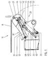
- the tail lift shown in Fig. 1 has a parallelogram-shaped lifting mechanism 20 with two parallel support arms 21 , to which a platform is articulated, and with a lifting cylinder (not shown) acting on a support arm 21 for lifting and lowering the platform and with a parallel cylinder (not shown) to tip the platform to the ground.
- the platform is pivotally mounted on the two support arms 21 about the upper platform pivot point 33 between a horizontal working position (FIG. 5) and a stowed position and has a platform fixed part 31 on which the platform tip is pivotally mounted as a platform folding part 32 . By folding over the platform folding part 32 by 180 °, the platform can be folded into a platform package 30 , as shown in FIG. 5.
- the support arm 21 forms the upper parallelogram strut indicated by dash-dotted lines in FIG. 1 and is rotatably mounted on the one hand on a fixed connection bracket 25 of the tail lift in the upper support arm pivot point 22 and on the other hand on the fixed platform part 31 in the upper platform pivot point 33 .
- the lower parallelogram strut which is also indicated by dash-dotted lines in FIG. 1, is rotatably mounted on the one hand on the connection bracket 25 in the lower parallelogram point 23 and on the other hand on the fixed platform part 31 in the lower platform pivot point, which coincidentally coincides with point 46 in FIG.
- the platform package 30 is shown in its stowed position raised under the loading floor 11 of a vehicle body 10 .
- the platform package 30 which is rotatably connected to the support arms 21 at the platform pivot point 33 rests on the roller 43 , which is angled upward at the pivot point 44
- Angle lever 40 is rotatably mounted.
- the first arm 41 of the angle lever 40 is fixedly mounted on the connection bracket 25 at the pivot point 45 and the second arm 42 on the support arm 21 at the pivot point 46 .
- the stowage position of the platform package 30 is reached when the fixed platform part 31 abuts the bottom of the rectangular tubular end of the vehicle body 10.
- the first arm 40 is designed as a telescopic arm with a plurality of adjustment holes 48 and the second arm 42 with an alternative bearing hole 47 .
- Fig. 2 shows the unfolding of the platform package 30, which is done by lowering the support arms 21 according to the support arm radius 24 .
- the distance between the two fulcrums 45, 46 is shortened, as a result of which the angle lever 40 rises upwards and raises the platform package 30 with respect to the support arms 21.
- the pivot curve 35 described here by the platform package 30 shows the required space for the unfolding process of the platform package 30.
- Fig. 3 the support arms 21 are lowered to the floor.
- the resulting further shortening of the distance between the two lever pivot points 45, 46 has raised the angle lever 40 further upward relative to the support arm 21, so that the roller 43 has set the platform package 30 up to just before the vertical pivot position (top dead center).
- the conditions are shown in a so-called deep tail lift extension, in which the distance E min of the support arm pivot point 22 to the ground is minimal.
- the maximum lever lengths of the two arms 41, 42 must be selected in order to bring the platform package 30 close to the top dead center.
- FIG. 4 corresponds to FIG. 3, but with the difference that the distance E max of the support arm pivot point 22 from the ground corresponds to the maximum distance.
- the first arm 41 is set to its maximum and the second arm 42 to its minimum lever length.
- the further pivoting of the platform package 30 beyond the top dead center into the horizontal working position is now carried out manually, in accordance with the pivot curve 36 described by the platform package 30.
- a corresponding spring relief is provided over this approximately 90 ° pivoting range, but this is not shown.
- FIG. 5 shows the unfolding of the platform package 30 by opening the platform folding part 32 in accordance with the pivoting curve 37 by 180 °, which results in the platform 34 shown in dashed lines in its horizontal working position.
- the foldable tail lift can be used for loading and unloading in a known manner. Folding and stowing after the work cycle is done in reverse order.
Landscapes
- Engineering & Computer Science (AREA)
- Transportation (AREA)
- Mechanical Engineering (AREA)
- Vehicle Step Arrangements And Article Storage (AREA)
Abstract
Description
- Die vorliegende Erfindung betrifft eine Hubladebühne für ein Fahrzeug, mit einem Hubwerk, das mindestens einen drehbar gelagerten Tragarm und eine an diesem verschwenkbar gelagerte Plattform aufweist, die zu einem Plattformpaket faltbar ist, welches nach Herumschwenken um mehr als 90° in Richtung Tragarm durch Anheben des Tragarms in eine Verstaustellung verfahrbar ist, sowie mit einem Führungselement, auf dem das herumgeschwenkte Plattformpaket beim Anheben und Absenken des Tragarms abgestützt ist.
- Faltbare Hubladebühnen haben wie Standard Hubladebühnen ein parallelogrammförmiges Hubwerk, welches fest am Fahrzeug montiert ist. Die Plattformspitze (Plattformfaltteil) ist einmal faltbar, und dieses zusammengefaltete Plattformpaket wird dann auf die beiden parallelen Tragarme des Hubwerks herumgeschwenkt und durch hydraulisches Hochschwenken der Tragarme unter dem Fahrzeugaufbau verstaut. Das 180°-Falten des Plattformfaltteils zum Plattformpaket erfolgt immer manuell, manchmal federunterstützt. Das Herumschwenken des Plattformpakets erfolgt in den ersten etwas mehr als 90° von der waagerechten Arbeitsposition in die Senkrechte (oberer Totpunkt) federunterstützt und ebenfalls von Hand.
- Bei bekannten Hubladebühnen wird das Plattformpaket über den oberen Totpunkt in Fahrtrichtung herumgeschwenkt, bis das Plattformpaket mit der Unterseite des Plattformfaltteils an einer fahrzeugseitig ortsfesten Rolle anliegt. Beim Hochschwenken der Tragarme legt sich das Plattformpaket dann auf der Rolle entsprechend waagrecht, um danach auf den Tragarmen aufzuliegen und vollends in seine Verstauposition verfahren zu werden. Sobald das Plattformpaket auf den Tragarmen aufliegt, beschreibt es den gleichen Radius wie die Tragarme. Solange das Plattformpaket durch die Rolle geführt wird, beschreibt die äußere Kante des Plattformpakets eine Schwenkkurve, die den benötigten Freiraum unter dem Fahrzeugaufbau vorgibt. Dabei sind Lage und Anstellwinkel des Plattformpakets an der ortsfesten Rolle abhängig vom Absenkwinkel der am Boden aufliegenden Tragarme. Da sich dieser Absenkwinkel entsprechend der Beladung (Einfederung) des Fahrzeugs oder aufgrund von Bodenunebenheiten ändert, ist bei stark eingefedertem Fahrzeug der Anstellwinkel des Plattformpakets an der Rolle sehr flach, so dass das Plattformpaket vom Bediener mit hohem Kraftaufwand in die Arbeitsposition geschwenkt werden muss.
- Da das Plattformpaket unter den Fahrzeugaufbau hochgeschwenkt wird, muss das Plattformpaket zwangsläufig niedriger sein als die Unterkante des Fahrzeugsaufbaus. Hierbei sind noch zusätzlich der Federweg der Fahrzeugfederung und ein unebenes Gelände zu berücksichtigen. Da heute einerseits Fahrzeuge zur Gewinnung von Volumen immer niedriger gebaut werden und andererseits größere Plattform zur Erhöhung der Ladesicherheit gefordert werden, besteht hier ein Zielkonflikt.
- Der Erfindung liegt daher die Aufgabe zugrunde, eine Hubladebühne der eingangs genannten Art dahingehend weiterzubilden, dass der für das Hochschwenken des Plattformpakets in seine Verstaustellung erforderliche Freiraum unterhalb des Fahrzeugaufbaus reduziert werden kann.
- Diese Aufgabe wird erfindungsgemäß dadurch gelöst, dass das Führungselement ortsveränderlich gelagert und mit dem Hubwerk derart bewegungsgekoppelt ist, dass bei abgesenktem Tragarm und zumindest im unteren Schwenkbereich des Tragarms das Plattformpaket am Führungselement abgestützt ist.
- Erfindungsgemäß ist das Führungselement nicht ortsfest angeordnet, sondern beispielsweise in einem ortsfesten Drehpunkt gelagert, wobei die Drehbewegung des Führungselements durch das Hubwerk, insbesondere den Tragarm, gesteuert wird. Der Anstellwinkel des Plattformpakets an das ortsveränderliche Führungselement ist erfindungsgemäß praktisch unabhängig vom Absenkwinkel der Tragarme und wird daher so steil eingestellt, dass das Plattformpaket vom Bediener mit dem stets gleichen geringen Kraftaufwand in die Arbeitsposition geschwenkt werden kann.
- Besonders bevorzugte Ausführungsformen der Erfindung zeichnen sich dadurch aus, dass das Führungselement bei abgesenktem Tragarm weiter in den Schwenkbereich des Plattformpakets eingreift als bei angehobenem Tragarm und dass das herumgeschwenkte Plattformpaket während des gesamten Anhebe- und Absenkvorgangs des Tragarms am Führungselement abgestützt ist.
- Vorzugsweise ist das Führungselement an einem nach oben abgewinkelten Winkelhebel vorgesehen, dessen erster Arm ortsfest an der Hubladebühne und dessen zweiter Arm am Hubwerk drehbar gelagert ist. Beim Hochschwenken des Tragarms wird der Winkelhebel gestreckt, so dass die vom Plattformpaket beim Anheben und Absenken des Tragarms beschriebene Schwenkkurve flacher als bei einem fest montierten Führungselement verläuft. Beim Absenken des Tragarms wird das Plattformpaket vom Führungselement in Richtung des oberen Totpunkts aufstellt. Damit wird erreicht, dass das Führungselement immer etwa in der Mitte des Plattformpakets angreift und daher immer eine genügend große, abwärts gerichtete Gewichtskomponente übrig bleibt, so dass sich das Plattformpaket sicher aufstellt.
- Die erfindungsgemäße Lagerung des Führungselements an einem Winkelhebel ist bei allen Hubladebühnen, auch solchen mit durchgehendem und mitfahrendem Unterfahrschutz, verwendbar.
- Besonders bevorzugt ist das Führungselement als Rolle ausgebildet und im Gelenkdrehpunkt des Winkelhebels drehbar gelagert. Diese Ausführung des Führungselements als Rolle im Gelenkdrehpunkt des Winkelhebels ist einfach und kostengünstig.
- Weiterhin bevorzugt ist einer oder beide Arme des Winkelhebels in der Länge verstellbar, um die optimalen Hebellängen des Winkelhebels einstellen zu können. Wenn die optimalen Hebellängen eingestellt sind, ist automatisch die optimale Schwenkkurve des Plattformpakets beim Anheben und Absenken des Tragarms erreicht.
- Weitere vorteilhafte Ausgestaltungen der Erfindung sind Gegenstand der Unteransprüche. Weitere Vorteile der Erfindung ergeben sich aus der Beschreibung und der Zeichnung. Ebenso können die vorstehend genannten und die noch weiter aufgeführten Merkmale je für sich oder zu mehreren in beliebigen Kombinationen Verwendung finden. Die gezeigte und beschriebene Ausführungsform ist nicht als abschließende Aufzählung zu verstehen, sondern hat vielmehr beispielhaften Charakter für die Schilderung der Erfindung.
- Es zeigen:
- Fig. 1
- eine Seitenansicht der erfindungsgemäßen Hubladebühne mit dem in seine Verstaustellung angehobenen Plattformpaket;
- Fig. 2
- die Hubladebühne der Fig. 1 mit dem etwa auf halbe Höhe abgesenkten Plattformpaket;
- Fig. 3
- die Hubladebühne der Fig. 1 mit dem auf den Boden abgesenkten Plattformpaket;
- Fig. 4
- die in Fig. 1 gezeigte Hubladebühne, jedoch montiert an einem Fahrzeug, bei dem die Hubladebühne in ihrer maximalen Entfernung zum Erdboden angeordnet ist; und
- Fig. 5
- das Plattformpaket der in Fig. 4 gezeigten Hubladebühne in seiner horizontalen Arbeitsstellung in zusammengefaltetem und entfaltetem Zustand.
- Die in Fig. 1 gezeigte Hubladebühne hat ein parallelogrammförmiges Hubwerk 20 mit zwei parallelen Tragarmen 21, an denen eine Plattform angelenkt ist, und mit einem am einem Tragarm 21 angreifenden Hubzylinder (nicht gezeigt) zum Heben und Senken der Plattform und mit einem Parallelzylinder (nicht gezeigt) zum Abkippen der Plattform auf den Boden. Die Plattform ist an den beiden Tragarmen 21 um den oberen Plattformdrehpunkt 33 zwischen einer horizontalen Arbeitsstellung (Fig. 5) und einer Verstaustellung verschwenkbar gelagert und hat ein Plattformfestteil 31, an dem die Plattformspitze als Plattformfaltteil 32 schwenkbar gelagert ist. Durch Umklappen des Plattformfaltteils 32 um 180° lässt sich die Plattform zu einem Plattformpaket 30 zusammenfalten, wie in Fig. 5 gezeigt ist.
- Der Tragarm 21 bildet die in Fig. 1 strichpunktiert angedeutete obere Parallelogrammstrebe und ist einerseits an einer ortsfesten Anschlusskonsole 25 der Hubladebühne im oberen Tragarmdrehpunkt 22 und andererseits am Plattformfestteil 31 im oberen Plattformdrehpunkt 33 drehbar gelagert. Die untere Parallelogrammstrebe, die in Fig. 1 ebenfalls strichpunktiert angedeutet ist, ist einerseits an der Anschlusskonsole 25 im unteren Parallelogrammpunkt 23 und andererseits am Plattformfestteil 31 im unteren Plattformdrehpunkt, der in Fig.1 zufällig mit dem Punkt 46 zusammenfällt, drehbar gelagert.
- In Fig. 1 ist das Plattformpaket 30 in seiner unter den Ladeboden 11 eines Fahrzeugaufbaus 10 angehobenen Verstaustellung gezeigt. Das im Plattformdrehpunkt 33 mit dem Tragarmen 21 drehbar verbundene Plattformpaket 30 liegt auf der Rolle 43 auf, die im Gelenkdrehpunkt 44 eines nach oben abgewinkelten Winkelhebels 40 drehbar gelagert ist. Der erste Arm 41 des Winkelhebels 40 ist an der Anschlusskonsole 25 ortsfest im Drehpunkt 45 und der zweite Arm 42 am Tragarm 21 im Drehpunkt 46 gelagert. Die Verstaustellung des Plattformpakets 30 ist erreicht, wenn das Plattformfestteils 31 unten am rechteckrohrförmigen Ende des Fahrzeugaufbaus 10 anliegt. Um die Hebellänge der Arme 41, 42 verstellen zu können, ist der erste Arm 40 als Teleskoparm mit mehreren Verstelllöchern 48 und der zweite Arm 42 mit einem alternativen Lagerloch 47 ausgebildet.
- Fig. 2 zeigt das Ausfalten des Plattformpakets 30, was durch Absenken der Tragarme 21 entsprechend dem Tragarmradius 24 erfolgt. Hierbei verkürzt sich der Abstand der beiden Hebeldrehpunkte 45, 46, wodurch sich der Winkelhebel 40 nach oben aufrichtet und das Plattformpaket 30 gegenüber den Tragarmen 21 anhebt. Die hierbei vom Plattformpaket 30 beschriebene Schwenkkurve 35 zeigt den benötigten Freiraum für den Ausfaltvorgang des Plattformpakets 30.
- In Fig. 3 sind die Tragarme 21 auf den Boden abgesenkt. Die hierbei erfolgte weitere Abstandsverkürzung der beiden Hebeldrehpunkte 45, 46 hat den Winkelhebel 40 gegenüber dem Tragarm 21 noch weiter nach oben aufgerichtet, so dass die Rolle 43 das Plattformpaket 30 bis kurz vor die senkrechte Schwenkstellung (oberer Totpunkt) aufgestellt hat. In Fig. 3 sind die Verhältnisse bei einem sogenannten tiefen Hubladebühnenanbau dargestellt, bei dem der Abstand Emin des Tragarmdrehpunktes 22 zum Boden minimal klein ist. Hierbei müssen die Hebellängen der beiden Arme 41, 42 maximal gewählt sein, um das Plattformpaket 30 nahe an den oberen Totpunkt heranzubringen.
- Fig. 4 entspricht Fig. 3, jedoch mit dem Unterschied, dass der Abstand Emax des Tragarmdrehpunktes 22 zum Erdboden der maximalen Entfernung entspricht. Um das Plattformpaket 30 nahe an den oberen Totpunkt zu bringen, ist der erste Arm 41 auf seine maximale und der zweite Arm 42 auf seine minimale Hebellänge eingestellt. Das weitere Verschwenken des Plattformpakets 30 über den oberen Totpunkt hinaus in die horizontale Arbeitsstellung erfolgt nunmehr von Hand, entsprechend der vom Plattformpaket 30 beschriebenen Schwenkkurve 36. Über diesen ca. 90°-Schwenkbereich ist eine entsprechende Federentlastung vorgesehen, die jedoch nicht dargestellt ist.
- Fig. 5 zeigt das Entfalten des Plattformpakets 30 durch Aufklappen des Plattformfaltteils 32 entsprechend der Schwenkkurve 37 um 180°, wodurch sich die gestrichelt dargestellte Plattform 34 in ihrer horizontalen Arbeitsstellung ergibt. Nunmehr kann die faltbare Hubladebühne auf bekannte Art und Weise zum Be- und Entladen eingesetzt werden. Das Einfalten und Verstauen nach dem Arbeitsspiel erfolgt in umgekehrter Reihenfolge.
- Alle Figuren zeigen weder die die Hub- und Senkfunktion ausführenden Hubzylinder noch das Widerlager, welches das Plattformfestteil 31 in der horizontalen Arbeitsstellung hält.
Claims (21)
- Hubladebühne für ein Fahrzeug, mit einem Hubwerk (20), das mindestens einen drehbar gelagerten Tragarm (21) und eine an diesem verschwenkbar gelagerte Plattform (34) aufweist, die zu einem Plattformpaket (30) faltbar ist, welches nach Herumschwenken um mehr als 90° in Richtung Tragarm (21) durch Anheben des Tragarms (21) in eine Verstaustellung verfahrbar ist, sowie mit einem Führungselement (43), auf dem das herumgeschwenkte Plattformpaket (30) beim Anheben und Absenken des Tragarms (21) abgestützt ist,
dadurch gekennzeichnet,
dass das Führungselement (43) ortsveränderlich gelagert und mit dem Hubwerk (20) derart bewegungsgekoppelt ist, dass bei abgesenktem Tragarm (21) und zumindest im unteren Schwenkbereich des Tragarms (21) das Plattformpaket (30) am Führungselement (43) abgestützt ist. - Hubladebühne nach Anspruch 1, dadurch gekennzeichnet, dass das Führungselement (43) bei abgesenktem Tragarm (21) weiter in den Schwenkbereich des Plattformpakets (30) eingreift als bei angehobenem Tragarm (21).
- Hubladebühne nach Anspruch 1 oder 2, dadurch gekennzeichnet, dass das Führungselement (43) um einen ortsfesten, insbesondere an der Hubladebühne vorgesehenen, Drehpunkt (45) verschwenkbar gelagert ist.
- Hubladebühne nach einem der vorhergehenden Ansprüche, dadurch gekennzeichnet, dass das herumgeschwenkte Plattformpaket (30) während des gesamten Anhebe- und Absenkvorgangs des Tragarms (21) am Führungselement (43) abgestützt ist.
- Hubladebühne nach einem der vorhergehenden Ansprüche, dadurch gekennzeichnet, dass das Führungselement (43) an einem nach oben abgewinkelten Winkelhebel (40) vorgesehen ist, dessen erster Arm (41) ortsfest an der Hubladebühne und dessen zweiter Arm (42) am Hubwerk (20) drehbar gelagert ist.
- Hubladebühne nach Anspruch 5, dadurch gekennzeichnet, dass der erste Arm (41) des Winkelhebels (40) an einer Flanschkonsole (25) des Hubwerks (20) drehbar gelagert ist.
- Hubladebühne nach Anspruch 5 oder 6, dadurch gekennzeichnet, dass der zweite Arm (42) des Winkelhebels (40) am Tragarm (21) oder an einem daran befestigten Teil drehbar gelagert ist.
- Hubladebühne nach einem der Ansprüche 5 bis 7, dadurch gekennzeichnet, dass sich der Abstand der Drehpunkte (45, 46) der beiden Arme (41, 42) des Winkelhebels (40) beim Anheben des Tragarms (21) vergrößert.
- Hubladebühne nach einem der Ansprüche 5 bis 8, dadurch gekennzeichnet, dass das Führungselement (43) im Bereich des Gelenkdrehpunktes (44) des Winkelhebels (40), insbesondere im Gelenkdrehpunkt (44), drehbar gelagert ist.
- Hubladebühne nach einem der Ansprüche 5 bis 9, dadurch gekennzeichnet, dass einer oder beide Arme (41, 42) des Winkelhebels (40) in der Hebellänge verstellbar sind.
- Hubladebühne nach einem der vorhergehenden Ansprüche, dadurch gekennzeichnet, dass das Führungselement (43) eine drehbar gelagerte Rolle ist.
- Hubladebühne für ein Fahrzeug, mit einem Hubwerk (20), das mindestens einen drehbar gelagerten Tragarm (21) und eine an diesem verschwenkbar gelagerte Plattform (34) aufweist, die zu einem Plattform paket (30) faltbar ist, welches nach Herumschwenken um mehr als 90° in Richtung Tragarm (21) durch Anheben des Tragarms (21) in eine Verstaustellung verfahrbar ist, sowie mit einem Führungselement (43), auf dem das herumgeschwenkte Plattformpaket (30) beim Anheben und Absenken des Tragarms (21) abgestützt ist, wobei das Führungselement (43) ortsveränderlich gelagert und mit dem Hubwerk (20) derart bewegungsgekoppelt ist, dass bei abgesenktem Tragarm (21) und zumindest im unteren Schwenkbereich des Tragarms (21) das Plattformpaket (30) am Führungselement (43) abgestützt ist,
dadurch gekennzeichnet,
dass das Führungselement (43) an einem nach oben abgewinkelten Winkelhebel (40) vorgesehen ist, dessen erster Arm (41) ortsfest an der Hubladebühne und dessen zweiter Arm (42) am Hubwerk (20) drehbar gelagert ist. - Hubladebühne nach Anspruch 1, dadurch gekennzeichnet, dass der erste Arm (41) des Winkelhebels (40) an einer Flanschkonsole (25) des Hubwerks (20) drehbar gelagert ist.
- Hubladebühne nach Anspruch 1 oder 2, dadurch gekennzeichnet, dass der zweite Arm (42) des Winkelhebels (40) am Tragarm (21) oder an einem daran befestigten Teil drehbar gelagert ist.
- Hubladebühne nach einem der vorhergehenden Ansprüche, dadurch gekennzeichnet, dass sich der Abstand der Drehpunkte (45, 46) der beiden Arme (41, 42) des Winkelhebels (40) beim Anheben des Tragarms (21) vergrößert.
- Hubladebühne nach einem der vorhergehenden Ansprüche, dadurch gekennzeichnet, dass das Führungselement (43) im Bereich des Gelenkdrehpunktes (44) des Winkelhebels (40), insbesondere im Gelenkdrehpunkt (44), drehbar gelagert ist.
- Hubladebühne nach einem der vorhergehenden Ansprüche, dadurch gekennzeichnet, dass einer oder beide Arme (41, 42) des Winkelhebels (40) in der Hebellänge verstellbar sind.
- Hubladebühne nach einem der vorhergehenden Ansprüche, dadurch gekennzeichnet, dass das Führungselement (43) eine drehbar gelagerte Rolle ist.
- Hubladebühne nach einem der vorhergehenden Ansprüche, dadurch gekennzeichnet, dass das Führungselement (43) bei abgesenktem Tragarm (21) weiter in den Schwenkbereich des Plattformpakets (30) eingreift als bei angehobenem Tragarm (21).
- Hubladebühne nach einem der vorhergehenden Ansprüche, dadurch gekennzeichnet, dass das Führungselement (43) um einen ortsfesten, insbesondere an der Hubladebühne vorgesehenen, Drehpunkt (45) verschwenkbar gelagert ist.
- Hubladebühne nach einem der vorhergehenden Ansprüche, dadurch gekennzeichnet, dass das herumgeschwenkte Plattformpaket (30) während des gesamten Anhebe- und Absenkvorgangs des Tragarms (21) am Führungselement (43) abgestützt ist.
Priority Applications (1)
| Application Number | Priority Date | Filing Date | Title |
|---|---|---|---|
| EP03014663A EP1491396A1 (de) | 2003-06-27 | 2003-06-27 | Hubladebühne mit faltbarer Plattform |
Applications Claiming Priority (1)
| Application Number | Priority Date | Filing Date | Title |
|---|---|---|---|
| EP03014663A EP1491396A1 (de) | 2003-06-27 | 2003-06-27 | Hubladebühne mit faltbarer Plattform |
Publications (1)
| Publication Number | Publication Date |
|---|---|
| EP1491396A1 true EP1491396A1 (de) | 2004-12-29 |
Family
ID=33395886
Family Applications (1)
| Application Number | Title | Priority Date | Filing Date |
|---|---|---|---|
| EP03014663A Withdrawn EP1491396A1 (de) | 2003-06-27 | 2003-06-27 | Hubladebühne mit faltbarer Plattform |
Country Status (1)
| Country | Link |
|---|---|
| EP (1) | EP1491396A1 (de) |
Cited By (1)
| Publication number | Priority date | Publication date | Assignee | Title |
|---|---|---|---|---|
| EP1609670A1 (de) * | 2004-06-22 | 2005-12-28 | MBB Liftsystems AG | Hubladebühne |
Citations (5)
| Publication number | Priority date | Publication date | Assignee | Title |
|---|---|---|---|---|
| DE3228829A1 (de) * | 1982-08-02 | 1984-02-09 | Emil Dautel GmbH, 7105 Leingarten | Ladevorrichtung fuer lastfahrzeugaufbauten |
| DE3737651A1 (de) * | 1987-11-06 | 1989-05-18 | Gerd Baer | Vorrichtung fuer eine unterfalt-ladebordwand |
| EP0361008A2 (de) * | 1988-09-29 | 1990-04-04 | MBB Förder- und Hebesysteme GmbH | Hubladebühne für Fahrzeuge |
| US4930973A (en) * | 1989-03-30 | 1990-06-05 | Waltco Truck Equipment Co., Inc. | Tiltable tailgate lift |
| BE1007254A3 (nl) * | 1993-06-30 | 1995-05-02 | Dhollandia Naamloze Vennootsch | Laadinrichting voor vrachtvoertuigen. |
-
2003
- 2003-06-27 EP EP03014663A patent/EP1491396A1/de not_active Withdrawn
Patent Citations (5)
| Publication number | Priority date | Publication date | Assignee | Title |
|---|---|---|---|---|
| DE3228829A1 (de) * | 1982-08-02 | 1984-02-09 | Emil Dautel GmbH, 7105 Leingarten | Ladevorrichtung fuer lastfahrzeugaufbauten |
| DE3737651A1 (de) * | 1987-11-06 | 1989-05-18 | Gerd Baer | Vorrichtung fuer eine unterfalt-ladebordwand |
| EP0361008A2 (de) * | 1988-09-29 | 1990-04-04 | MBB Förder- und Hebesysteme GmbH | Hubladebühne für Fahrzeuge |
| US4930973A (en) * | 1989-03-30 | 1990-06-05 | Waltco Truck Equipment Co., Inc. | Tiltable tailgate lift |
| BE1007254A3 (nl) * | 1993-06-30 | 1995-05-02 | Dhollandia Naamloze Vennootsch | Laadinrichting voor vrachtvoertuigen. |
Cited By (2)
| Publication number | Priority date | Publication date | Assignee | Title |
|---|---|---|---|---|
| EP1609670A1 (de) * | 2004-06-22 | 2005-12-28 | MBB Liftsystems AG | Hubladebühne |
| DE102004030075B4 (de) * | 2004-06-22 | 2014-09-11 | Mbb Palfinger Gmbh | Hubladebühne |
Similar Documents
| Publication | Publication Date | Title |
|---|---|---|
| DE69014523T2 (de) | Schwenkrampe mit Hebeplattform und Betriebsverfahren. | |
| EP1538271B1 (de) | Erweiterbarer Container | |
| EP0221911B1 (de) | Wagenheber | |
| DE8910933U1 (de) | Klapptritt für Wohnmobile und dgl. Fahrzeuge | |
| EP3609833B1 (de) | Hebebühne zum anheben von fahrzeugen | |
| DE1580662B2 (de) | Unterhalb einer ladeflaeche, insbesondere eines fahrzeuges, verstaubare ladebuehne | |
| DE2831286A1 (de) | Einrichtung zum vollstaendigen zusammenlegen oder ausfalten des aus zwei gelenkelementen bestehenden auslegers eines teleskopmastkrans | |
| DE2705979C3 (de) | Lastwagen mit in seiner Längsrichtung verschiebbarem Ladebodenabschnitt | |
| CH645580A5 (de) | Lastkraftwagen mit einer ladepritsche und einem aufbau. | |
| WO2019180167A1 (de) | Mobilkran mit zweiteiligem spitzenausleger sowie verfahren zum aufrichten des auslegersystems eines derartigen mobilkrans | |
| EP1491396A1 (de) | Hubladebühne mit faltbarer Plattform | |
| DE4113828C2 (de) | Fahrzeug zum Mähen | |
| WO2019243412A1 (de) | GROßKRAN MIT AUSLEGER | |
| DE2755986A1 (de) | Hebesystem fuer einen kran | |
| AT526869B1 (de) | Teleskopausleger mit ausklappbarem Mast | |
| DE3512940A1 (de) | Auffahrrampe fuer fahrzeuge | |
| DE2357839C3 (de) | Hebebühne | |
| DE2250562B2 (de) | Hebebuehne, insbesondere ladebordwand fuer kraftfahrzeuge | |
| DE2114402B2 (de) | Zusammenklappbarer Kran | |
| DE202019003552U1 (de) | Aus- und einfahrbare Trittstufenanordnung für einen Kastenwagen, Caravan oder dergleichen | |
| DE202009007142U1 (de) | Plattformlift zur Anbringung an einem Wasserfahrzeug | |
| DE9420228U1 (de) | Entbindungsbett | |
| CH679029A5 (de) | ||
| DE2444132B2 (de) | Wagenheber | |
| DE29608244U1 (de) | Frontkraftheber |
Legal Events
| Date | Code | Title | Description |
|---|---|---|---|
| PUAI | Public reference made under article 153(3) epc to a published international application that has entered the european phase |
Free format text: ORIGINAL CODE: 0009012 |
|
| 17P | Request for examination filed |
Effective date: 20040224 |
|
| AK | Designated contracting states |
Kind code of ref document: A1 Designated state(s): AT BE BG CH CY CZ DE DK EE ES FI FR GB GR HU IE IT LI LU MC NL PT RO SE SI SK TR |
|
| AX | Request for extension of the european patent |
Extension state: AL LT LV MK |
|
| AKX | Designation fees paid |
Designated state(s): DE FR GB |
|
| GRAP | Despatch of communication of intention to grant a patent |
Free format text: ORIGINAL CODE: EPIDOSNIGR1 |
|
| STAA | Information on the status of an ep patent application or granted ep patent |
Free format text: STATUS: THE APPLICATION IS DEEMED TO BE WITHDRAWN |
|
| 18D | Application deemed to be withdrawn |
Effective date: 20060613 |