EP1490570B1 - Verbessertes zuhaltungsscheibenschloss - Google Patents
Verbessertes zuhaltungsscheibenschloss Download PDFInfo
- Publication number
- EP1490570B1 EP1490570B1 EP03712155A EP03712155A EP1490570B1 EP 1490570 B1 EP1490570 B1 EP 1490570B1 EP 03712155 A EP03712155 A EP 03712155A EP 03712155 A EP03712155 A EP 03712155A EP 1490570 B1 EP1490570 B1 EP 1490570B1
- Authority
- EP
- European Patent Office
- Prior art keywords
- locking
- lock
- bolt
- disc
- lock case
- Prior art date
- Legal status (The legal status is an assumption and is not a legal conclusion. Google has not performed a legal analysis and makes no representation as to the accuracy of the status listed.)
- Expired - Lifetime
Links
- 230000033001 locomotion Effects 0.000 claims abstract description 16
- 238000006073 displacement reaction Methods 0.000 claims abstract description 9
- 230000001419 dependent effect Effects 0.000 claims abstract 2
- 238000004519 manufacturing process Methods 0.000 description 4
- 230000007812 deficiency Effects 0.000 description 1
- 238000009434 installation Methods 0.000 description 1
- 238000000034 method Methods 0.000 description 1
- 238000012986 modification Methods 0.000 description 1
- 230000004048 modification Effects 0.000 description 1
- 238000000465 moulding Methods 0.000 description 1
- 238000003825 pressing Methods 0.000 description 1
- 238000004080 punching Methods 0.000 description 1
- 239000000523 sample Substances 0.000 description 1
Images
Classifications
-
- E—FIXED CONSTRUCTIONS
- E05—LOCKS; KEYS; WINDOW OR DOOR FITTINGS; SAFES
- E05B—LOCKS; ACCESSORIES THEREFOR; HANDCUFFS
- E05B21/00—Locks with lamelliform tumblers which are not set by the insertion of the key and in which the tumblers do not follow the movement of the bolt e.g. Chubb-locks
-
- E—FIXED CONSTRUCTIONS
- E05—LOCKS; KEYS; WINDOW OR DOOR FITTINGS; SAFES
- E05B—LOCKS; ACCESSORIES THEREFOR; HANDCUFFS
- E05B63/00—Locks or fastenings with special structural characteristics
- E05B63/12—Locks or fastenings with special structural characteristics with means carried by the bolt for interlocking with the keeper
- E05B63/127—Locks or fastenings with special structural characteristics with means carried by the bolt for interlocking with the keeper the bolt having an additional rotating bolt or movement
-
- Y—GENERAL TAGGING OF NEW TECHNOLOGICAL DEVELOPMENTS; GENERAL TAGGING OF CROSS-SECTIONAL TECHNOLOGIES SPANNING OVER SEVERAL SECTIONS OF THE IPC; TECHNICAL SUBJECTS COVERED BY FORMER USPC CROSS-REFERENCE ART COLLECTIONS [XRACs] AND DIGESTS
- Y10—TECHNICAL SUBJECTS COVERED BY FORMER USPC
- Y10T—TECHNICAL SUBJECTS COVERED BY FORMER US CLASSIFICATION
- Y10T70/00—Locks
- Y10T70/50—Special application
- Y10T70/5093—For closures
- Y10T70/5155—Door
- Y10T70/5199—Swinging door
- Y10T70/5246—Dead bolts
- Y10T70/5296—Single
- Y10T70/5319—Sliding
- Y10T70/5341—Key operable only
-
- Y—GENERAL TAGGING OF NEW TECHNOLOGICAL DEVELOPMENTS; GENERAL TAGGING OF CROSS-SECTIONAL TECHNOLOGIES SPANNING OVER SEVERAL SECTIONS OF THE IPC; TECHNICAL SUBJECTS COVERED BY FORMER USPC CROSS-REFERENCE ART COLLECTIONS [XRACs] AND DIGESTS
- Y10—TECHNICAL SUBJECTS COVERED BY FORMER USPC
- Y10T—TECHNICAL SUBJECTS COVERED BY FORMER US CLASSIFICATION
- Y10T70/00—Locks
- Y10T70/70—Operating mechanism
- Y10T70/7441—Key
- Y10T70/7486—Single key
- Y10T70/7508—Tumbler type
- Y10T70/752—Sliding tumblers
- Y10T70/7531—Transverse
-
- Y—GENERAL TAGGING OF NEW TECHNOLOGICAL DEVELOPMENTS; GENERAL TAGGING OF CROSS-SECTIONAL TECHNOLOGIES SPANNING OVER SEVERAL SECTIONS OF THE IPC; TECHNICAL SUBJECTS COVERED BY FORMER USPC CROSS-REFERENCE ART COLLECTIONS [XRACs] AND DIGESTS
- Y10—TECHNICAL SUBJECTS COVERED BY FORMER USPC
- Y10T—TECHNICAL SUBJECTS COVERED BY FORMER US CLASSIFICATION
- Y10T70/00—Locks
- Y10T70/70—Operating mechanism
- Y10T70/7441—Key
- Y10T70/7486—Single key
- Y10T70/7508—Tumbler type
- Y10T70/7537—Rotary or swinging tumblers
- Y10T70/7542—Single set
- Y10T70/7548—Directly key engaged
Definitions
- the invention relates to a disc tumbler lock according to the preamble of claim 1.
- one desirable feature of locks is that they should be practically unpickable or picking the lock would be at least as difficult as possible.
- a known method, by which the lock type being object of the invention has been tried to be picked is based on the fact that the lock bolt is pushed inwards to the lock, whereby the locking pin is pressed against the edge of the locking channel of the locking disc preventing movement of the bolt. If the locking disc is then lifted through the keyhole, the location of the locking channel branch of the locking disc permitting displacement of the bolt into the lock case can be probed. By repeating the operation for the part of each locking disc the positions of locking discs permitting opening of the lock can be detected and the lock can be opened.
- the locking channels with different notches or hooks, into which the locking pin may grip when one tries to detect the right position of the locking discs.
- the gripping means are, instead of the locking channel, being arranged to the outer edge of the locking discs so that in a picklocking situation they cooperate with a separate gripping member arranged in the lock case.
- the guidance for the movement of the locking discs allows the movement caused by pressing in the bolt, as a result of which the said gripping means come into contact with each other.
- the movement of the locking discs is guided by two pins, which are arranged in guiding grooves in the locking discs. One of these pins is supported to the lock case in a stationary manner and the other in a displaceable manner.
- the solution is complicated and the entire structure disadvantageous from the viewpoint of manufacturing and assembling.
- An aim of the invention is to provide a new improved disc tumbler lock, of which the deficiencies appearing in the disclosed known solution are essentially eliminated.
- an aim of the invention is to provide a disc tumbler lock, which has excellent properties for resisting picklocking, the structure of which is as simple and reliable as possible and the manufacturing and assembling of which may be carried out more advantageously than before.
- the aims of the invention can be achieved in a way as is described in claim 1 and in the other claims.
- the invention is known of the combination that at least one of the locking discs is equipped, in a manner known per se, with gripping means, which, when the bolt is pressed inwards to the lock case, are arranged to cooperate with counter means arranged in the lock case for preventing the displacing of said at least one locking disc, and that the said at least one locking disc is spring-loaded to turn the locking disc around a first guiding member against a second guiding member so that the said second guiding member guides the said at least one locking disc substantially towards the head of the bolt to be pushed out from the lock case.
- the guiding members of the locking discs are firmly and reliably secured to the lock case, but the second guiding member is arranged to support the spring-loaded locking discs in a normal situation substantially only in the direction outwards from the lock case.
- the counter means arranged in the lock case advantageously comprise one or more gripping members provided at the bottom of the lock case. These may be provided already in the manufacturing stage of the structural elements and no separate installation measures are needed for them.
- the said second guiding member can advantageously be arranged to guide also the reciprocating motions of the bolt out from the lock case and into the lock case, which secures guiding of the bolt and further enables to minimize the number of components required.
- the locking pin and the locking channels of the locking discs are preferably arranged in the direction transversal with respect to the bolt's direction of displacement at the same position as the said gripping means and the counter means thereof. In this way it can be secured that the locking pin, as a result of the inward pushing movement exerted at the head of the bolt, presses the locking discs correspondingly so that the gripping members engage each other.
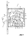
- the reference number 1 refers to a lock case, which comprises a front plate 2.
- the lock case includes a keyhole 7 as well as a bolt 3 movable to-and-fro through an opening in the front plate by means of a key of the lock (not shown).
- the displacement of the bolt takes place through guiding surfaces 6.
- the bolt is a so-called hook bolt, which includes a bolt body 3b, displaceable inside the lock case, in which a hook part 3a is turnably supported by means of a pin 4.
- the lock case includes a guiding groove 5 for the pin 4 in order to guide the movements of the hook part 3a.
- the operation of the hook bolt 3 as such is apparent from the publication WO 02/16716 A1.
- the hook bolt lock is one advantageous embodiment of the invention, but the invention is by no means limited to disc tumbler locks provided with hook bolts, but the invention can be applied as well to disc tumbler locks provided with other bolt types such as dead bolts.
- the lock case 1 is provided with a number of locking discs 13, which, in a manner known per se, are separated from each other by intermediate discs (only partly shown).
- the locking discs are equipped with a locking channel 17, which cooperates with a locking pin 12 secured to the bolt, and with a guiding surface 13a, that can be affected with a key of the lock to displace the locking discs upwards in the figures against the force of return springs 14 of the locking discs.
- This displacing movement is to arrange the locking discs 13 so that the locking pin 12 is located in each of the selecting situations at the position of transversal branches 17a of the locking channel, whereby the bolt may be moved from a protruding position inwards to open the lock or from a retracted position outwards in order to lock the lock.
- the lock case includes guiding members i.e. in this case guiding pins 8 and 9, which are arranged to guide the movements of the bolt via guiding grooves 10 and 11 arranged for the bolt.
- the guiding pins 8 and 9 are arranged to guide also the movements of the locking discs 13.
- the locking discs comprise a guiding groove 15, which is in cooperation with the guiding pin 8, and a guiding surface 16, which in a normal situation is pressed by the springs 14 in cooperation with the guiding pin 9.
- the locking discs further comprise gripping members 18 and the lock case includes gripping members 19, which in a certain picklocking situation of the lock are arranged to cooperate with each other as described below in more detail.
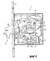
- the Figure 2 shows more precisely the operation of the solution according to the invention in a picklocking situation, when a force F is exerted at the bolt's 3 head pushing the bolt inwards.
- the locking pin 12 presses the locking discs 13 against the force of the springs 14 via the counter surfaces of the locking channels transversal with respect to the direction of movement of the bolt. Consequently, the locking discs turn around the guiding pin 8 so that the gripping members 18 and 19 grip to each other and thus prevent the displacement of the locking discs through the key hole 7 aimed to probe the right position for opening the lock.
- the springs 14 of the locking discs have in this case a double function, on the one hand they keep the locking discs normally in disorder, whereby the locking discs prevent the displacing of the bolt without the right key for the lock and, on the other hand, they urge the locking discs against the guiding pin 9 so that the gripping members 18 and 19 normally stay apart from each other and allow the displacement of the locking discs with the key of the lock in order to open the lock. From the viewpoint of the operation of the invention it is thus essential and sufficient that the locking discs have such a guiding surface 16, which cooperates with the guiding pin in the direction towards the bolt head to be protruded, but allows the displacement in the opposite direction.
- the gripping members 18 and 19 may be implemented in many different ways.
- the gripping members 19 may advantageously be arranged directly to the lock case during its manufacturing phase e.g. by pressure moulding or by punching.
- the location of the gripping members in the lock can be changed.
- the mutual role of the guiding pins 8 and 9 can be changed, as long as at the same time the placing and functioning of the springs 14 and the functional preconditions of other parts of the lock are taken into consideration.
Landscapes
- Lock And Its Accessories (AREA)
- Medicines Containing Antibodies Or Antigens For Use As Internal Diagnostic Agents (AREA)
- Steering Devices For Bicycles And Motorcycles (AREA)
- Amplifiers (AREA)
- Quick-Acting Or Multi-Walled Pipe Joints (AREA)
- Polishing Bodies And Polishing Tools (AREA)
- Acyclic And Carbocyclic Compounds In Medicinal Compositions (AREA)
- Transition And Organic Metals Composition Catalysts For Addition Polymerization (AREA)
- Switch Cases, Indication, And Locking (AREA)
- Supporting Of Heads In Record-Carrier Devices (AREA)
- Feeding And Guiding Record Carriers (AREA)
- Air Bags (AREA)
- Preventing Unauthorised Actuation Of Valves (AREA)
- Holding Or Fastening Of Disk On Rotational Shaft (AREA)
- Packaging For Recording Disks (AREA)
- Motorcycle And Bicycle Frame (AREA)
- Toys (AREA)
Claims (5)
- Zuhaltungsscheibenschloss, das einen Schlosskasten (1), welcher einen mit einem Schlüssel des Schlosses verschiebbaren Riegel (3) und mehrere mit Verriegelungskanälen (17) versehene Verriegelungsscheiben (13) enthält, die mit dem Schlüssel des Schlosses gegen die Kraft einer Feder (14) verschoben werden können, um das Schloss zu öffnen und die Bewegungen, die der Schlosskasten erfährt, mit stationären Führungsgliedern (8, 9) zu führen, und einen Verriegelungsstift (12) umfasst, der von den Bewegungen des Riegels abhängig ist und zum Zusammenwirken mit den Verriegelungskanälen (17) der Verriegelungsscheiben angeordnet ist, gekennzeichnet durch die Kombination, dass mindestens eine der Verriegelungsscheiben (13) auf an sich bekannte Weise mit Greifmitteln (18) versehen ist, die so angeordnet sind, dass sie beim Drücken des Riegels (3) nach innen zum Schlosskasten mit Gegenmitteln (19) zusammenwirken, die in dem Schlosskasten angeordnet sind, um das Verschieben der mindestens einen Verriegelungsscheibe (13) zu verhindern, und dass die mindestens eine Verriegelungsscheibe (13) federbelastet ist, um die Verriegelungsscheibe um ein erstes Führungsglied (8) gegen ein zweites Führungsglied (9)zu drehen, so dass das zweite Führungsglied (9) die mindestens eine Verriegelungsscheibe (13) im Wesentlichen in Richtung zum Kopf des Riegels (3) führt, so dass sie aus dem Schlosskasten herausragt.
- Zuhaltungsscheibenschloss nach Anspruch 1, dadurch gekennzeichnet, dass es sich bei der die Verriegelungsscheibe (13) drehenden Feder um eine Rückholfeder (14) für die Verriegelungsscheibe handelt.
- Zuhaltungsscheibenschloss nach Anspruch 1 oder 2, dadurch gekennzeichnet, dass die im Schlosskasten angeordneten Gegenmittel (19) ein oder mehrere Greifglieder (19) umfassen, die am Boden des Schlosskastens angeordnet sind.
- Zuhaltungsscheibenschloss nach einem der vorhergehenden Ansprüche, dadurch gekennzeichnet, dass das zweite Führungsglied (9) so angeordnet ist, dass es auch die Hin- und Herbewegungen des Riegels (3) aus dem Schlosskasten heraus und in den Schlosskasten führen kann.
- Zuhaltungsscheibenschloss nach einem der vorhergehenden Ansprüche, dadurch gekennzeichnet, dass der Verriegelungsstift (12) und die Verriegelungskanäle (17) der Verriegelungsscheiben in der quer zu der der Verschiebungsrichtung des Riegels verlaufenden Richtung in der gleichen Position wie die Greifmittel (18) und die Gegenmittel (19) davon angeordnet sind.
Priority Applications (1)
| Application Number | Priority Date | Filing Date | Title |
|---|---|---|---|
| SI200330096T SI1490570T1 (sl) | 2002-03-27 | 2003-03-14 | Izboljsana kolutna zaskocna kljucavnica |
Applications Claiming Priority (3)
| Application Number | Priority Date | Filing Date | Title |
|---|---|---|---|
| FI20020587 | 2002-03-27 | ||
| FI20020587A FI114330B (fi) | 2002-03-27 | 2002-03-27 | Haittalevylukko |
| PCT/FI2003/000196 WO2003080969A1 (en) | 2002-03-27 | 2003-03-14 | Improved disc tumbler lock |
Publications (2)
| Publication Number | Publication Date |
|---|---|
| EP1490570A1 EP1490570A1 (de) | 2004-12-29 |
| EP1490570B1 true EP1490570B1 (de) | 2005-08-17 |
Family
ID=8563656
Family Applications (1)
| Application Number | Title | Priority Date | Filing Date |
|---|---|---|---|
| EP03712155A Expired - Lifetime EP1490570B1 (de) | 2002-03-27 | 2003-03-14 | Verbessertes zuhaltungsscheibenschloss |
Country Status (17)
| Country | Link |
|---|---|
| US (1) | US7178371B2 (de) |
| EP (1) | EP1490570B1 (de) |
| KR (1) | KR100955162B1 (de) |
| AT (1) | ATE302315T1 (de) |
| AU (1) | AU2003216937A1 (de) |
| CA (1) | CA2477141A1 (de) |
| DE (1) | DE60301342T2 (de) |
| DK (1) | DK1490570T3 (de) |
| EA (1) | EA005745B1 (de) |
| ES (1) | ES2246469T3 (de) |
| FI (1) | FI114330B (de) |
| HR (1) | HRP20040831A2 (de) |
| IL (2) | IL163738A0 (de) |
| MX (1) | MXPA04008872A (de) |
| NO (1) | NO336799B1 (de) |
| PL (1) | PL208004B1 (de) |
| WO (1) | WO2003080969A1 (de) |
Families Citing this family (5)
| Publication number | Priority date | Publication date | Assignee | Title |
|---|---|---|---|---|
| TWD119818S1 (zh) * | 2006-06-05 | 2007-11-11 | 傑森納亞沙基蘇維塞 | 用於鎖具的制動栓片 |
| TWD119819S1 (zh) * | 2006-06-05 | 2007-11-11 | 傑森納亞沙基蘇維塞 | 用於鎖具的制動栓片 |
| PL2212493T3 (pl) * | 2007-10-31 | 2011-10-31 | Cisa Spa | Zamek odporny na włamanie |
| IT1403933B1 (it) * | 2011-02-11 | 2013-11-08 | Securemme S R L | Serratura di sicurezza |
| US10267064B2 (en) | 2011-10-12 | 2019-04-23 | Zephyr Lock, Llc | Lock with linearly operating latch |
Family Cites Families (6)
| Publication number | Priority date | Publication date | Assignee | Title |
|---|---|---|---|---|
| GB386502A (en) * | 1932-04-16 | 1933-01-19 | Feinstahlwerke Traisen Ag | Safety lock |
| US2617289A (en) * | 1946-10-11 | 1952-11-11 | Bell Telephone Labor Inc | Key actuated double custody lock |
| NL173782C (nl) * | 1970-10-30 | 1984-03-01 | Spaci Sa | Klavierslot met beveiligingsinrichting tegen inbraak. |
| US3762192A (en) * | 1971-10-27 | 1973-10-02 | Italiane Serrature Affini Sa C | Antilock-picking device |
| US3879968A (en) * | 1974-01-31 | 1975-04-29 | Bell Telephone Labor Inc | Key operated lock |
| IT1295184B1 (it) | 1997-09-18 | 1999-05-04 | Italiana Serrature Affini | Dispositivo antieffrazione per una serratura con nottolini a piastre. |
-
2002
- 2002-03-27 FI FI20020587A patent/FI114330B/fi not_active IP Right Cessation
-
2003
- 2003-03-14 MX MXPA04008872A patent/MXPA04008872A/es active IP Right Grant
- 2003-03-14 WO PCT/FI2003/000196 patent/WO2003080969A1/en not_active Ceased
- 2003-03-14 EA EA200401260A patent/EA005745B1/ru not_active IP Right Cessation
- 2003-03-14 IL IL16373803A patent/IL163738A0/xx unknown
- 2003-03-14 US US10/509,005 patent/US7178371B2/en not_active Expired - Fee Related
- 2003-03-14 HR HR20040831A patent/HRP20040831A2/xx not_active Application Discontinuation
- 2003-03-14 DK DK03712155T patent/DK1490570T3/da active
- 2003-03-14 DE DE60301342T patent/DE60301342T2/de not_active Expired - Lifetime
- 2003-03-14 PL PL371501A patent/PL208004B1/pl not_active IP Right Cessation
- 2003-03-14 AT AT03712155T patent/ATE302315T1/de not_active IP Right Cessation
- 2003-03-14 KR KR1020047015207A patent/KR100955162B1/ko not_active Expired - Fee Related
- 2003-03-14 AU AU2003216937A patent/AU2003216937A1/en not_active Abandoned
- 2003-03-14 ES ES03712155T patent/ES2246469T3/es not_active Expired - Lifetime
- 2003-03-14 CA CA002477141A patent/CA2477141A1/en not_active Abandoned
- 2003-03-14 EP EP03712155A patent/EP1490570B1/de not_active Expired - Lifetime
-
2004
- 2004-08-25 IL IL163738A patent/IL163738A/en not_active IP Right Cessation
- 2004-10-27 NO NO20044632A patent/NO336799B1/no not_active IP Right Cessation
Also Published As
| Publication number | Publication date |
|---|---|
| IL163738A0 (en) | 2005-12-18 |
| DE60301342D1 (de) | 2005-09-22 |
| WO2003080969A1 (en) | 2003-10-02 |
| PL208004B1 (pl) | 2011-02-28 |
| FI20020587A0 (fi) | 2002-03-27 |
| FI20020587A7 (fi) | 2003-09-28 |
| FI114330B (fi) | 2004-09-30 |
| DE60301342T2 (de) | 2006-06-08 |
| US7178371B2 (en) | 2007-02-20 |
| KR20040097218A (ko) | 2004-11-17 |
| ATE302315T1 (de) | 2005-09-15 |
| KR100955162B1 (ko) | 2010-04-28 |
| HRP20040831A2 (en) | 2005-06-30 |
| IL163738A (en) | 2009-12-24 |
| MXPA04008872A (es) | 2005-06-20 |
| AU2003216937A1 (en) | 2003-10-08 |
| ES2246469T3 (es) | 2006-02-16 |
| EA200401260A1 (ru) | 2005-02-24 |
| PL371501A1 (en) | 2005-06-27 |
| CA2477141A1 (en) | 2003-10-02 |
| DK1490570T3 (da) | 2005-11-14 |
| EA005745B1 (ru) | 2005-06-30 |
| NO20044632L (no) | 2004-10-27 |
| EP1490570A1 (de) | 2004-12-29 |
| US20050126237A1 (en) | 2005-06-16 |
| NO336799B1 (no) | 2015-11-02 |
Similar Documents
| Publication | Publication Date | Title |
|---|---|---|
| JP2526317B2 (ja) | 磁石カ―ド錠 | |
| CN110499962B (zh) | 家用电器的门锁 | |
| CA2096488C (en) | Mechanism for releasably locking sashes in door- or window frames | |
| US8161783B2 (en) | Quickly rekeyable lock cylinder and plug assembly thereof | |
| US10738505B2 (en) | Door lock with door switch | |
| CA2519391A1 (en) | Arrangement for guiding the deadlocking of a latch bolt in a door lock | |
| WO2015130668A1 (en) | Sidebit operated interchangeable core control lug | |
| EP1490570B1 (de) | Verbessertes zuhaltungsscheibenschloss | |
| CA2345690C (en) | Improved pushbutton lock | |
| KR100722125B1 (ko) | 키 스위치 | |
| JP5764019B2 (ja) | スライド式門扉 | |
| KR20200053356A (ko) | 안전잠금식 퀵커플러 | |
| JP3984168B2 (ja) | シリンダケースを備えたシリンダ錠とシリンダ錠用平鍵 | |
| GB2268221A (en) | Multi-point lock | |
| CN210685638U (zh) | 具有防误触发机构的锁体 | |
| EP1377720B1 (de) | Zuhaltungsschloss | |
| EP0668424B1 (de) | Türschloss mit Riegel und Falle | |
| CN219733064U (zh) | 锁具闭锁装置 | |
| AU2011255903A1 (en) | Lock cylinder with L shaped wafer tumblers | |
| CN86201523U (zh) | 自动抽屉锁 |
Legal Events
| Date | Code | Title | Description |
|---|---|---|---|
| PUAI | Public reference made under article 153(3) epc to a published international application that has entered the european phase |
Free format text: ORIGINAL CODE: 0009012 |
|
| 17P | Request for examination filed |
Effective date: 20041004 |
|
| AK | Designated contracting states |
Kind code of ref document: A1 Designated state(s): AT BE BG CH CY CZ DE DK EE ES FI FR GB GR HU IE IT LI LU MC NL PT RO SE SI SK TR |
|
| AX | Request for extension of the european patent |
Extension state: AL LT LV MK |
|
| GRAP | Despatch of communication of intention to grant a patent |
Free format text: ORIGINAL CODE: EPIDOSNIGR1 |
|
| GRAS | Grant fee paid |
Free format text: ORIGINAL CODE: EPIDOSNIGR3 |
|
| GRAA | (expected) grant |
Free format text: ORIGINAL CODE: 0009210 |
|
| AK | Designated contracting states |
Kind code of ref document: B1 Designated state(s): AT BE BG CH CY CZ DE DK EE ES FI FR GB GR HU IE IT LI LU MC NL PT RO SE SI SK TR |
|
| AX | Request for extension of the european patent |
Extension state: AL LT LV MK |
|
| PG25 | Lapsed in a contracting state [announced via postgrant information from national office to epo] |
Ref country code: CH Free format text: LAPSE BECAUSE OF FAILURE TO SUBMIT A TRANSLATION OF THE DESCRIPTION OR TO PAY THE FEE WITHIN THE PRESCRIBED TIME-LIMIT Effective date: 20050817 Ref country code: LI Free format text: LAPSE BECAUSE OF FAILURE TO SUBMIT A TRANSLATION OF THE DESCRIPTION OR TO PAY THE FEE WITHIN THE PRESCRIBED TIME-LIMIT Effective date: 20050817 Ref country code: BE Free format text: LAPSE BECAUSE OF FAILURE TO SUBMIT A TRANSLATION OF THE DESCRIPTION OR TO PAY THE FEE WITHIN THE PRESCRIBED TIME-LIMIT Effective date: 20050817 Ref country code: RO Free format text: LAPSE BECAUSE OF FAILURE TO SUBMIT A TRANSLATION OF THE DESCRIPTION OR TO PAY THE FEE WITHIN THE PRESCRIBED TIME-LIMIT Effective date: 20050817 Ref country code: AT Free format text: LAPSE BECAUSE OF FAILURE TO SUBMIT A TRANSLATION OF THE DESCRIPTION OR TO PAY THE FEE WITHIN THE PRESCRIBED TIME-LIMIT Effective date: 20050817 Ref country code: FI Free format text: LAPSE BECAUSE OF FAILURE TO SUBMIT A TRANSLATION OF THE DESCRIPTION OR TO PAY THE FEE WITHIN THE PRESCRIBED TIME-LIMIT Effective date: 20050817 |
|
| REG | Reference to a national code |
Ref country code: GB Ref legal event code: FG4D |
|
| REG | Reference to a national code |
Ref country code: CH Ref legal event code: EP |
|
| REG | Reference to a national code |
Ref country code: IE Ref legal event code: FG4D |
|
| REF | Corresponds to: |
Ref document number: 60301342 Country of ref document: DE Date of ref document: 20050922 Kind code of ref document: P |
|
| REG | Reference to a national code |
Ref country code: DK Ref legal event code: T3 |
|
| PG25 | Lapsed in a contracting state [announced via postgrant information from national office to epo] |
Ref country code: GR Free format text: LAPSE BECAUSE OF FAILURE TO SUBMIT A TRANSLATION OF THE DESCRIPTION OR TO PAY THE FEE WITHIN THE PRESCRIBED TIME-LIMIT Effective date: 20051117 Ref country code: BG Free format text: LAPSE BECAUSE OF FAILURE TO SUBMIT A TRANSLATION OF THE DESCRIPTION OR TO PAY THE FEE WITHIN THE PRESCRIBED TIME-LIMIT Effective date: 20051117 |
|
| REG | Reference to a national code |
Ref country code: SE Ref legal event code: TRGR |
|
| REG | Reference to a national code |
Ref country code: EE Ref legal event code: FG4A Ref document number: E000176 Country of ref document: EE Effective date: 20051011 |
|
| PG25 | Lapsed in a contracting state [announced via postgrant information from national office to epo] |
Ref country code: PT Free format text: LAPSE BECAUSE OF FAILURE TO SUBMIT A TRANSLATION OF THE DESCRIPTION OR TO PAY THE FEE WITHIN THE PRESCRIBED TIME-LIMIT Effective date: 20060117 |
|
| REG | Reference to a national code |
Ref country code: ES Ref legal event code: FG2A Ref document number: 2246469 Country of ref document: ES Kind code of ref document: T3 |
|
| PG25 | Lapsed in a contracting state [announced via postgrant information from national office to epo] |
Ref country code: HU Free format text: LAPSE BECAUSE OF FAILURE TO SUBMIT A TRANSLATION OF THE DESCRIPTION OR TO PAY THE FEE WITHIN THE PRESCRIBED TIME-LIMIT Effective date: 20060218 |
|
| REG | Reference to a national code |
Ref country code: CH Ref legal event code: PL |
|
| PG25 | Lapsed in a contracting state [announced via postgrant information from national office to epo] |
Ref country code: LU Free format text: LAPSE BECAUSE OF NON-PAYMENT OF DUE FEES Effective date: 20060331 Ref country code: MC Free format text: LAPSE BECAUSE OF NON-PAYMENT OF DUE FEES Effective date: 20060331 |
|
| ET | Fr: translation filed | ||
| PLBE | No opposition filed within time limit |
Free format text: ORIGINAL CODE: 0009261 |
|
| STAA | Information on the status of an ep patent application or granted ep patent |
Free format text: STATUS: NO OPPOSITION FILED WITHIN TIME LIMIT |
|
| 26N | No opposition filed |
Effective date: 20060518 |
|
| PG25 | Lapsed in a contracting state [announced via postgrant information from national office to epo] |
Ref country code: CY Free format text: LAPSE BECAUSE OF FAILURE TO SUBMIT A TRANSLATION OF THE DESCRIPTION OR TO PAY THE FEE WITHIN THE PRESCRIBED TIME-LIMIT Effective date: 20050817 |
|
| PGFP | Annual fee paid to national office [announced via postgrant information from national office to epo] |
Ref country code: SI Payment date: 20090223 Year of fee payment: 7 |
|
| REG | Reference to a national code |
Ref country code: SI Ref legal event code: KO00 Effective date: 20101018 |
|
| PG25 | Lapsed in a contracting state [announced via postgrant information from national office to epo] |
Ref country code: SI Free format text: LAPSE BECAUSE OF NON-PAYMENT OF DUE FEES Effective date: 20100315 |
|
| PGFP | Annual fee paid to national office [announced via postgrant information from national office to epo] |
Ref country code: DK Payment date: 20110315 Year of fee payment: 9 Ref country code: IE Payment date: 20110328 Year of fee payment: 9 |
|
| PGFP | Annual fee paid to national office [announced via postgrant information from national office to epo] |
Ref country code: CZ Payment date: 20110222 Year of fee payment: 9 Ref country code: TR Payment date: 20110223 Year of fee payment: 9 Ref country code: SK Payment date: 20110221 Year of fee payment: 9 Ref country code: FR Payment date: 20110404 Year of fee payment: 9 Ref country code: NL Payment date: 20110316 Year of fee payment: 9 |
|
| PGFP | Annual fee paid to national office [announced via postgrant information from national office to epo] |
Ref country code: DE Payment date: 20110325 Year of fee payment: 9 Ref country code: ES Payment date: 20110322 Year of fee payment: 9 |
|
| PGFP | Annual fee paid to national office [announced via postgrant information from national office to epo] |
Ref country code: IT Payment date: 20110329 Year of fee payment: 9 |
|
| REG | Reference to a national code |
Ref country code: NL Ref legal event code: V1 Effective date: 20121001 |
|
| REG | Reference to a national code |
Ref country code: LT Ref legal event code: MM9D Effective date: 20120314 |
|
| PG25 | Lapsed in a contracting state [announced via postgrant information from national office to epo] |
Ref country code: CZ Free format text: LAPSE BECAUSE OF NON-PAYMENT OF DUE FEES Effective date: 20120314 |
|
| REG | Reference to a national code |
Ref country code: DK Ref legal event code: EBP |
|
| REG | Reference to a national code |
Ref country code: SK Ref legal event code: MM4A Ref document number: E 267 Country of ref document: SK Effective date: 20120314 |
|
| REG | Reference to a national code |
Ref country code: FR Ref legal event code: ST Effective date: 20121130 |
|
| REG | Reference to a national code |
Ref country code: IE Ref legal event code: MM4A |
|
| PG25 | Lapsed in a contracting state [announced via postgrant information from national office to epo] |
Ref country code: SK Free format text: LAPSE BECAUSE OF NON-PAYMENT OF DUE FEES Effective date: 20120314 Ref country code: FR Free format text: LAPSE BECAUSE OF NON-PAYMENT OF DUE FEES Effective date: 20120402 Ref country code: IE Free format text: LAPSE BECAUSE OF NON-PAYMENT OF DUE FEES Effective date: 20120314 |
|
| REG | Reference to a national code |
Ref country code: DE Ref legal event code: R119 Ref document number: 60301342 Country of ref document: DE Effective date: 20121002 |
|
| PG25 | Lapsed in a contracting state [announced via postgrant information from national office to epo] |
Ref country code: IT Free format text: LAPSE BECAUSE OF NON-PAYMENT OF DUE FEES Effective date: 20120314 |
|
| PG25 | Lapsed in a contracting state [announced via postgrant information from national office to epo] |
Ref country code: NL Free format text: LAPSE BECAUSE OF NON-PAYMENT OF DUE FEES Effective date: 20121001 |
|
| PG25 | Lapsed in a contracting state [announced via postgrant information from national office to epo] |
Ref country code: DK Free format text: LAPSE BECAUSE OF NON-PAYMENT OF DUE FEES Effective date: 20120331 |
|
| REG | Reference to a national code |
Ref country code: ES Ref legal event code: FD2A Effective date: 20130710 |
|
| PG25 | Lapsed in a contracting state [announced via postgrant information from national office to epo] |
Ref country code: ES Free format text: LAPSE BECAUSE OF NON-PAYMENT OF DUE FEES Effective date: 20120315 |
|
| PG25 | Lapsed in a contracting state [announced via postgrant information from national office to epo] |
Ref country code: TR Free format text: LAPSE BECAUSE OF NON-PAYMENT OF DUE FEES Effective date: 20120314 |
|
| PG25 | Lapsed in a contracting state [announced via postgrant information from national office to epo] |
Ref country code: DE Free format text: LAPSE BECAUSE OF NON-PAYMENT OF DUE FEES Effective date: 20121002 |
|
| PGFP | Annual fee paid to national office [announced via postgrant information from national office to epo] |
Ref country code: EE Payment date: 20210227 Year of fee payment: 19 |
|
| PGFP | Annual fee paid to national office [announced via postgrant information from national office to epo] |
Ref country code: SE Payment date: 20210311 Year of fee payment: 19 Ref country code: GB Payment date: 20210308 Year of fee payment: 19 |
|
| GBPC | Gb: european patent ceased through non-payment of renewal fee |
Effective date: 20220314 |
|
| PG25 | Lapsed in a contracting state [announced via postgrant information from national office to epo] |
Ref country code: SE Free format text: LAPSE BECAUSE OF NON-PAYMENT OF DUE FEES Effective date: 20220315 Ref country code: GB Free format text: LAPSE BECAUSE OF NON-PAYMENT OF DUE FEES Effective date: 20220314 |
|
| PG25 | Lapsed in a contracting state [announced via postgrant information from national office to epo] |
Ref country code: EE Free format text: LAPSE BECAUSE OF NON-PAYMENT OF DUE FEES Effective date: 20220331 |