EP1489726A2 - Horizontalachsige elektrische Maschine - Google Patents
Horizontalachsige elektrische Maschine Download PDFInfo
- Publication number
- EP1489726A2 EP1489726A2 EP04102715A EP04102715A EP1489726A2 EP 1489726 A2 EP1489726 A2 EP 1489726A2 EP 04102715 A EP04102715 A EP 04102715A EP 04102715 A EP04102715 A EP 04102715A EP 1489726 A2 EP1489726 A2 EP 1489726A2
- Authority
- EP
- European Patent Office
- Prior art keywords
- spring
- base frame
- support ring
- support
- machine according
- Prior art date
- Legal status (The legal status is an assumption and is not a legal conclusion. Google has not performed a legal analysis and makes no representation as to the accuracy of the status listed.)
- Granted
Links
Images

Classifications
-
- H—ELECTRICITY
- H02—GENERATION; CONVERSION OR DISTRIBUTION OF ELECTRIC POWER
- H02K—DYNAMO-ELECTRIC MACHINES
- H02K1/00—Details of the magnetic circuit
- H02K1/06—Details of the magnetic circuit characterised by the shape, form or construction
- H02K1/12—Stationary parts of the magnetic circuit
- H02K1/18—Means for mounting or fastening magnetic stationary parts on to, or to, the stator structures
- H02K1/185—Means for mounting or fastening magnetic stationary parts on to, or to, the stator structures to outer stators
-
- H—ELECTRICITY
- H02—GENERATION; CONVERSION OR DISTRIBUTION OF ELECTRIC POWER
- H02K—DYNAMO-ELECTRIC MACHINES
- H02K5/00—Casings; Enclosures; Supports
- H02K5/24—Casings; Enclosures; Supports specially adapted for suppression or reduction of noise or vibrations
Definitions
- the present invention relates to the field of electrical machines. It relates to a horizontal-axis electrical machine according to the generic term of claim 1.
- Such a machine is e.g. known from DE-A1 -43 22 268.
- stator sheet metal body has a larger horizontal axis electrical machine in a plurality of one behind the other in the axial direction arranged and spaced apart support rings to store, each on two opposite sides by means of a support structure on the one below Base frame or floor are attached.
- a machine with one constructive structure is e.g. known from CH-A5-665 507. She draws is characterized by the fact that vibrations and thermal stresses occur be kept small during operation.
- the well-known attachment of the Stator sheet metal body allows easy assembly, easy accessibility of the to be welded construction parts and ensures a good quality of Welds.
- a disadvantage of the known type of mounting of the built-in stator is that for other types of vibration of the built-in stator, where vertical components occur, decoupling takes place only to a limited extent.
- the object is achieved by the entirety of the features of claim 1.
- the essence of the invention is between the ends of the spring and the associated one To provide support ring acting in the vertical direction spring elements. Due to the additional spring elements acting in the vertical direction even more complex vibrations are safely decoupled. Due to the compact arrangement the spring and the spring elements within the supporting structures is a simple one Coordination or detuning of the spring characteristics possible.
- a first preferred embodiment of the invention is characterized in that that the connecting elements each stand vertically on the base frame U-shaped support element and a horizontal between the spring and the Support element extending pipe section comprise, and that the pipe section Rectangular tube is.
- a further development of this embodiment is characterized in that the Pipe piece or rectangular tube welded to the spring and the support element and that the support element is welded to the base frame.
- a second preferred embodiment of the invention is characterized in that that the support ring, the spring elements and the spring are welded together are.
- Another advantageous embodiment of the machine according to the invention is distinguished is characterized in that the spring elements are horizontal between the spring and the associated support ring and encompass the support ring on both sides.
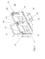
- FIG. 1 shows a section of a horizontal-axis electrical machine 10 according to FIG reproduced a preferred embodiment of the invention, the the resilient attachment of the built-in stator 11 of the machine 10 to an underlying one Base frame 18 shows.
- the built-in stator 11 with its stator laminated core is in a plurality of support rings arranged one behind the other in the axial direction 12 stored (see also Fig. 3), which in turn on opposite sides by means of individual vertical support structures 21 (19, 20, 21 in FIG. 3) on the base frame 18 are attached.
- the internal structure of the support structures 19, 20, 21 is shown in Fig. 1 in longitudinal section, in Fig. 2 in cross section, and in Fig. 3 in different Assembly steps (19 -> 20 -> 21) shown.
- a vertically standing spring 15 in Form an elongated rectangular plate at both ends with the associated one Support ring 12 firmly connected (see support structure 19 in Fig. 3).
- the connection is made via an upper spring element 13 and a lower spring element 17.
- the spring elements 13, 17 are horizontal plates that support the support ring 12 on both Reach sides (see Fig. 2).
- You are on the one hand with the support ring 12 and welded to the spring 15 on its outer end face.
- On the outside the spring 15 is welded to a piece of tube in the form of a rectangular tube 14, that has an elongated rectangular cross-section.
- the tube axis of the rectangular tube 14 is perpendicular to the surface of the spring 15.
- a support element 16 with a U-shaped Cross-sectional profile is vertical on the horizontal Base frame 18 welded that the support member 16, the spring 15 at three Encloses sides and the bottom plate of the Support element 16 is parallel to the spring 15 at a distance.
- this bottom plate is a rectangular recess 22 is provided, which the outer dimensions of the Rectangular tube 14 is adapted (see support structure 20 in Fig. 3).
- the state of the support structure projects from the rectangular tube 14 through the recess 22 and is welded to the base plate.
- Rectangular tube 14 can connect the spring 15 and bottom plate of the Support element 16 also over several round pieces of pipe or through a vertical Standing solid steel plate are made, as is similar in the beginning mentioned document DE-A1 -43 22 268 is shown.
- the spring 15 is asymmetrical to a horizontal central plane passing through the machine axis, i.e. the predominant length portion of the spring 15 is below the median plane.
- the two spring elements 13 and 17 are different are long and thick.
- the spring 15 lies symmetrically to the central plane. In this case, the spring elements are largely equal.
Landscapes
- Engineering & Computer Science (AREA)
- Power Engineering (AREA)
- Motor Or Generator Frames (AREA)
- Iron Core Of Rotating Electric Machines (AREA)
Abstract
Description
- Fig. 1
- in einem Ausschnitt den Längsschnitt durch eine federnde Befestigung eines Tragringes am Grundrahmen gemäss einem bevorzugten Ausführungsbeispiel der Erfindung;
- Fig. 2
- den Querschnitt durch die Befestigung aus Fig. 1; und
- Fig. 3
- in einem Ausschnitt die perspektivische Seitenansicht einer Maschine mit der Befestigung aus Fig. 1, wobei an verschiedenen Tragringen unterschiedliche Montageschritte bei der Tragstruktur 19, 20 und 21 dargestellt sind.
- Die Kombination aus Tragring 12 mit Feder 15 und U-förmigem Tragelement 16 bewirkt eine Entkopplung zwischen dem Einbaustator 11 und dem Grundrahmen 18 in horizontaler Richtung.
- Die horizontal angeordneten Federelemente 13, 17 bewirken eine vertikale Entkopplung zwischen Einbaustator 11 und Grundrahmen 18.
- Die Verbindung zwischen dem Tragelement 16 und dem Tragring mit Feder mittels des Rechteckrohres 14 gewährleistet eine steife Verbindung.
- Die Vertikalsteifigkeit wird durch die horizontal liegenden Federelemente 13, 17 beeinflusst.
- Die doppelte Federung durch die Feder 15 und die Federelemente 13, 17 ergibt eine verbesserte Entkopplung der Vier-Knoten-Schwingungen des Einbaustators 11 vom Grundrahmen 18.
- Es ist eine einfache Verstimmung (Abstimmung) der Federcharakteristik möglich.
- Es ist auch denkbar, anstelle der Schweissverbindungen Schraubverbindungen oder dgl. einzusetzen.
- 10
- elektrische Maschine (horizontalachsig)
- 11
- Einbaustator
- 12
- Tragring (mit Feder)
- 13,17
- Federelement
- 14
- Rechteckrohr (Rohrstück)
- 15
- Feder
- 16
- Tragelement (U-förmig)
- 18
- Grundrahmen
- 19,20,21
- Tragstruktur
- 22
- Aussparung (rechteckig)
Claims (7)
- Horizontalachsige elektrische Maschine (10) mit einem Einbaustator (11), welcher von einer Mehrzahl von parallelen, in axialer Richtung voneinander beabstandeten Tragringen (12) konzentrisch umgeben ist, die an ihrem Aussenumfang auf gegenüberliegenden Seiten jeweils mittels Tragstrukturen (19, 20, 21) mit einem sich in Achsrichtung erstreckenden Grundrahmen (18) verbunden sind, wobei innerhalb der Tragstrukturen (19, 20, 21) jeweils eine in horizontaler Richtung wirkende Feder (15) vorgesehen ist, welche die Form einer senkrecht stehenden länglichen Platte aufweist, die einerseits mit ihren Enden am zugehörigen Tragring (12) befestigt ist, und die andererseits mit ihrem frei durchbiegbaren Mittelteil über Verbindungselemente (14, 16) mit dem Grundrahmen (18) fest verbunden ist, dadurch gekennzeichnet, dass zwischen den Enden der Feder (15) und dem zugehörigen Tragring (12) in vertikaler Richtung wirkende Federelemente (13, 17) angeordnet sind.
- Maschine nach Anspruch 1, dadurch gekennzeichnet, dass die Verbindungselemente (14, 16) jeweils ein senkrecht auf dem Grundrahmen (18) stehendes U-förmiges Tragelement (16) und ein horizontal zwischen der Feder (15) und dem Tragelement (16) sich erstreckendes Rohrstück (14) umfassen.
- Maschine nach Anspruch 2, dadurch gekennzeichnet, dass das Rohrstück ein Rechteckrohr (14) ist.
- Maschine nach Anspruch 1, dadurch gekennzeichnet, dass der Tragring (12), die Federelemente (13, 17) und die Feder (15) miteinander verschweisst sind.
- Maschine nach einem der Ansprüche 2 oder 3, dadurch gekennzeichnet, dass das Rohrstück bzw. Rechteckrohr (14) mit der Feder (15) und dem Tragelement (16) verschweisst ist.
- Maschine nach Anspruch 5, dadurch gekennzeichnet, dass Tragelement (16) mit dem Grundrahmen (18) verschweisst ist.
- Maschine nach einem der Ansprüche 1 bis 6, dadurch gekennzeichnet, dass die Federelemente (13, 17) sich horizontal zwischen der Feder (15) und dem zugehörigen Tragring (12) erstrecken und den Tragring (12) beidseitig umgreifen.
Applications Claiming Priority (2)
| Application Number | Priority Date | Filing Date | Title |
|---|---|---|---|
| DE10327508A DE10327508A1 (de) | 2003-06-17 | 2003-06-17 | Horizontalachsige elektrische Maschine |
| DE10327508 | 2003-06-17 |
Publications (3)
| Publication Number | Publication Date |
|---|---|
| EP1489726A2 true EP1489726A2 (de) | 2004-12-22 |
| EP1489726A3 EP1489726A3 (de) | 2007-05-09 |
| EP1489726B1 EP1489726B1 (de) | 2015-04-01 |
Family
ID=33394874
Family Applications (1)
| Application Number | Title | Priority Date | Filing Date |
|---|---|---|---|
| EP04102715.2A Expired - Lifetime EP1489726B1 (de) | 2003-06-17 | 2004-06-15 | Horizontalachsige elektrische Maschine |
Country Status (3)
| Country | Link |
|---|---|
| US (1) | US6911761B2 (de) |
| EP (1) | EP1489726B1 (de) |
| DE (1) | DE10327508A1 (de) |
Cited By (3)
| Publication number | Priority date | Publication date | Assignee | Title |
|---|---|---|---|---|
| EP2456047A1 (de) * | 2010-11-22 | 2012-05-23 | Siemens AG | Elektrische Maschine mit mehreren Momentenstützelementen |
| CN106464042A (zh) * | 2014-03-26 | 2017-02-22 | Abb瑞士股份有限公司 | 电机 |
| EP3764517A1 (de) * | 2018-06-15 | 2021-01-13 | GE Energy Power Conversion Technology Ltd. | Gehäuse für eine elektrisch umlaufende maschine, stator und verfahren zum einsetzen eines stators in ein solches gehäuse |
Families Citing this family (1)
| Publication number | Priority date | Publication date | Assignee | Title |
|---|---|---|---|---|
| EP2924848A1 (de) * | 2014-03-26 | 2015-09-30 | ABB Technology AG | Abstützungsanordnung einer elektrischen Maschine |
Family Cites Families (15)
| Publication number | Priority date | Publication date | Assignee | Title |
|---|---|---|---|---|
| US1416371A (en) * | 1920-11-10 | 1922-05-16 | Minich Railway Appliance Corp | Car brake |
| GB540573A (en) * | 1939-04-18 | 1941-10-22 | Westinghouse Electric Int Co | Improvements in or relating to dynamo-electric machines |
| US2456612A (en) * | 1947-06-19 | 1948-12-21 | Westinghouse Electric Corp | Dynamoelectric machine |
| DE1083647B (de) * | 1954-12-16 | 1960-06-15 | Studio Ges Fuer Ind Und Modeph | Einrichtung an einem photographischen Apparat zur gemeinsamen Blenden- und Entfernungseinstellung |
| DE2158209C3 (de) * | 1971-11-18 | 1980-01-17 | Licentia Patent-Verwaltungs-Gmbh, 6000 Frankfurt | Befestigung des Ständerblechpakets im Gehäuse einer großen elektrischen Maschine |
| DE2301243A1 (de) | 1972-01-24 | 1973-08-02 | Gen Electric | Kernhalterung fuer dynamoelektrische maschine |
| SE404739B (sv) * | 1977-03-18 | 1978-10-23 | Asea Ab | Roterande elektrisk maskin |
| FR2521793A1 (fr) * | 1982-02-18 | 1983-08-19 | Alsthom Atlantique | Stator a suspension elastique pour machine dynamoelectrique synchrone |
| US4425523A (en) * | 1982-06-04 | 1984-01-10 | Westinghouse Electric Corp. | Core spring support system for a dynamoelectric machine |
| CH665507A5 (de) * | 1984-06-12 | 1988-05-13 | Bbc Brown Boveri & Cie | Horizontalachsige elektrische maschine mit einer einrichtung zur statorblechpaketbefestigung. |
| DE3920785A1 (de) * | 1988-09-23 | 1990-03-29 | Asea Brown Boveri | Horizontalachsige elektrische maschine |
| DE4322268A1 (de) * | 1993-07-05 | 1995-01-12 | Abb Management Ag | Horizontalachsige elektrische Maschine |
| US6091177A (en) * | 1999-03-22 | 2000-07-18 | Siemens Westinghouse Power Corporation | Spring mounting for an electric generator |
| DE19940630A1 (de) * | 1999-08-27 | 2001-03-01 | Asea Brown Boveri | Horizontalachsige elektrische Maschine |
| DE10013375A1 (de) * | 2000-03-17 | 2001-09-20 | Alstom Power Nv | Elektrische Maschine |
-
2003
- 2003-06-17 DE DE10327508A patent/DE10327508A1/de not_active Withdrawn
-
2004
- 2004-06-15 EP EP04102715.2A patent/EP1489726B1/de not_active Expired - Lifetime
- 2004-06-17 US US10/871,168 patent/US6911761B2/en not_active Expired - Lifetime
Cited By (6)
| Publication number | Priority date | Publication date | Assignee | Title |
|---|---|---|---|---|
| EP2456047A1 (de) * | 2010-11-22 | 2012-05-23 | Siemens AG | Elektrische Maschine mit mehreren Momentenstützelementen |
| US8917002B2 (en) | 2010-11-22 | 2014-12-23 | Siemens Aktiengesellschaft | Electric machine having a plurality of torque-support elements |
| CN106464042A (zh) * | 2014-03-26 | 2017-02-22 | Abb瑞士股份有限公司 | 电机 |
| US10110087B2 (en) | 2014-03-26 | 2018-10-23 | Abb Schweiz Ag | Electric machine |
| CN106464042B (zh) * | 2014-03-26 | 2018-11-02 | Abb瑞士股份有限公司 | 电机 |
| EP3764517A1 (de) * | 2018-06-15 | 2021-01-13 | GE Energy Power Conversion Technology Ltd. | Gehäuse für eine elektrisch umlaufende maschine, stator und verfahren zum einsetzen eines stators in ein solches gehäuse |
Also Published As
| Publication number | Publication date |
|---|---|
| US6911761B2 (en) | 2005-06-28 |
| DE10327508A1 (de) | 2005-01-27 |
| EP1489726B1 (de) | 2015-04-01 |
| EP1489726A3 (de) | 2007-05-09 |
| US20040256946A1 (en) | 2004-12-23 |
Similar Documents
| Publication | Publication Date | Title |
|---|---|---|
| CH665507A5 (de) | Horizontalachsige elektrische maschine mit einer einrichtung zur statorblechpaketbefestigung. | |
| EP3051668B1 (de) | Rotorsegment und Rotor einer elektrischen Maschine | |
| DE102012110147A1 (de) | Rotor für einen Asynchronmotor in gebauter Ausführung | |
| DE102011121584A1 (de) | Modulares Tragsystem zur Fixierung von Bauteilen | |
| DE2617388B2 (de) | Gekapselter Motorverdichter für Kältemaschinen | |
| DE102007013700A1 (de) | Dentalgeräterüttelvorrichtung | |
| DE3539298A1 (de) | Vorrichtung zur lagerung des staenders eines drehstromgenerators | |
| EP0633643B1 (de) | Horizontalachsige elektrische Maschine | |
| EP1489726B1 (de) | Horizontalachsige elektrische Maschine | |
| DE8717761U1 (de) | Walze für landwirtschaftliche Zwecke | |
| DE102016206206A1 (de) | Statorlamellenpaket für eine Elektromaschine bzw. Elektromaschine mit einem derartigen Statorlamellenpaket und Verfahren zur Herstellung einer solchen Elektromaschine | |
| EP2925545B1 (de) | Kopflageranordnung zur anbindung eines federbeins an einen fahrzeugaufbau | |
| DE2948148C2 (de) | ||
| DE102004060591A1 (de) | Tank für kryogene Medien sowie Verfahren und Vorrichtung zu dessen Zusammenbau | |
| DE102020114748A1 (de) | Elektrische Maschine mit gehäuseseitiger Anbindung eines Stators | |
| DE4109814C2 (de) | ||
| DE20309455U1 (de) | Verbundlenkerachse für eine hintere Radaufhängung eines Kraftfahrzeugs | |
| DE202018006147U1 (de) | Getriebesystem mit einem Motor | |
| DE202011003613U1 (de) | Zusammensetzbarer Leichtbauprofilträger | |
| DE102007062956B3 (de) | Montagehilfe für das Montieren von wenigstens zwei Kabelschuhen | |
| DE3039322C2 (de) | Stoßisolationsvorrichtung für eine Erdverdichtertrommel | |
| DE202014101667U1 (de) | Umschlingungsband zur Befestigung eines Tanks und Fahrzeug mit einem solchen Umschlingungsband | |
| DE2408743A1 (de) | Traggehaeuse fuer elektromagneten | |
| DE102005060063A1 (de) | Träger für ein Fahrzeug | |
| DE102018207885B4 (de) | Brechwalze und Verfahren zu deren Herstellung |
Legal Events
| Date | Code | Title | Description |
|---|---|---|---|
| PUAI | Public reference made under article 153(3) epc to a published international application that has entered the european phase |
Free format text: ORIGINAL CODE: 0009012 |
|
| AK | Designated contracting states |
Kind code of ref document: A2 Designated state(s): AT BE BG CH CY CZ DE DK EE ES FI FR GB GR HU IE IT LI LU MC NL PL PT RO SE SI SK TR |
|
| AX | Request for extension of the european patent |
Extension state: AL HR LT LV MK |
|
| PUAL | Search report despatched |
Free format text: ORIGINAL CODE: 0009013 |
|
| AK | Designated contracting states |
Kind code of ref document: A3 Designated state(s): AT BE BG CH CY CZ DE DK EE ES FI FR GB GR HU IE IT LI LU MC NL PL PT RO SE SI SK TR |
|
| AX | Request for extension of the european patent |
Extension state: AL HR LT LV MK |
|
| 17P | Request for examination filed |
Effective date: 20071016 |
|
| 17Q | First examination report despatched |
Effective date: 20071120 |
|
| AKX | Designation fees paid |
Designated state(s): DE GB |
|
| GRAP | Despatch of communication of intention to grant a patent |
Free format text: ORIGINAL CODE: EPIDOSNIGR1 |
|
| INTG | Intention to grant announced |
Effective date: 20141024 |
|
| GRAS | Grant fee paid |
Free format text: ORIGINAL CODE: EPIDOSNIGR3 |
|
| GRAA | (expected) grant |
Free format text: ORIGINAL CODE: 0009210 |
|
| AK | Designated contracting states |
Kind code of ref document: B1 Designated state(s): DE GB |
|
| REG | Reference to a national code |
Ref country code: GB Ref legal event code: FG4D Free format text: NOT ENGLISH |
|
| REG | Reference to a national code |
Ref country code: DE Ref legal event code: R096 Ref document number: 502004014871 Country of ref document: DE Effective date: 20150513 |
|
| REG | Reference to a national code |
Ref country code: DE Ref legal event code: R119 Ref document number: 502004014871 Country of ref document: DE |
|
| PLBE | No opposition filed within time limit |
Free format text: ORIGINAL CODE: 0009261 |
|
| STAA | Information on the status of an ep patent application or granted ep patent |
Free format text: STATUS: NO OPPOSITION FILED WITHIN TIME LIMIT |
|
| 26N | No opposition filed |
Effective date: 20160105 |
|
| GBPC | Gb: european patent ceased through non-payment of renewal fee |
Effective date: 20150701 |
|
| PG25 | Lapsed in a contracting state [announced via postgrant information from national office to epo] |
Ref country code: DE Free format text: LAPSE BECAUSE OF NON-PAYMENT OF DUE FEES Effective date: 20160101 Ref country code: GB Free format text: LAPSE BECAUSE OF NON-PAYMENT OF DUE FEES Effective date: 20150701 |