EP1489371B1 - Konditionierer - Google Patents
Konditionierer Download PDFInfo
- Publication number
- EP1489371B1 EP1489371B1 EP04019766A EP04019766A EP1489371B1 EP 1489371 B1 EP1489371 B1 EP 1489371B1 EP 04019766 A EP04019766 A EP 04019766A EP 04019766 A EP04019766 A EP 04019766A EP 1489371 B1 EP1489371 B1 EP 1489371B1
- Authority
- EP
- European Patent Office
- Prior art keywords
- mixer
- retainer
- conditioner according
- rotor
- product
- Prior art date
- Legal status (The legal status is an assumption and is not a legal conclusion. Google has not performed a legal analysis and makes no representation as to the accuracy of the status listed.)
- Expired - Lifetime
Links
Images

Classifications
-
- A—HUMAN NECESSITIES
- A23—FOODS OR FOODSTUFFS; TREATMENT THEREOF, NOT COVERED BY OTHER CLASSES
- A23N—MACHINES OR APPARATUS FOR TREATING HARVESTED FRUIT, VEGETABLES OR FLOWER BULBS IN BULK, NOT OTHERWISE PROVIDED FOR; PEELING VEGETABLES OR FRUIT IN BULK; APPARATUS FOR PREPARING ANIMAL FEEDING- STUFFS
- A23N17/00—Apparatus specially adapted for preparing animal feeding-stuffs
- A23N17/005—Apparatus specially adapted for preparing animal feeding-stuffs for shaping by moulding, extrusion, pressing, e.g. pellet-mills
-
- F—MECHANICAL ENGINEERING; LIGHTING; HEATING; WEAPONS; BLASTING
- F26—DRYING
- F26B—DRYING SOLID MATERIALS OR OBJECTS BY REMOVING LIQUID THEREFROM
- F26B17/00—Machines or apparatus for drying materials in loose, plastic, or fluidised form, e.g. granules, staple fibres, with progressive movement
- F26B17/18—Machines or apparatus for drying materials in loose, plastic, or fluidised form, e.g. granules, staple fibres, with progressive movement with movement performed by rotating helical blades or other rotary conveyors which may be heated moving materials in stationary chambers, e.g. troughs
- F26B17/20—Machines or apparatus for drying materials in loose, plastic, or fluidised form, e.g. granules, staple fibres, with progressive movement with movement performed by rotating helical blades or other rotary conveyors which may be heated moving materials in stationary chambers, e.g. troughs the axis of rotation being horizontal or slightly inclined
- F26B17/205—Machines or apparatus for drying materials in loose, plastic, or fluidised form, e.g. granules, staple fibres, with progressive movement with movement performed by rotating helical blades or other rotary conveyors which may be heated moving materials in stationary chambers, e.g. troughs the axis of rotation being horizontal or slightly inclined with multiple chambers, e.g. troughs, in superimposed arrangement
-
- F—MECHANICAL ENGINEERING; LIGHTING; HEATING; WEAPONS; BLASTING
- F26—DRYING
- F26B—DRYING SOLID MATERIALS OR OBJECTS BY REMOVING LIQUID THEREFROM
- F26B21/00—Arrangements for supplying or controlling air or other gases for drying solid materials or objects
- F26B21/20—Circulating air or gases in closed cycles, e.g. wholly within the drying enclosure
- F26B21/25—Circulating air or gases in closed cycles, e.g. wholly within the drying enclosure partly outside the drying enclosure
Definitions
- the invention relates to a conditioner, in particular for the production of conditioned feed or food.
- Conditioners are used individually as processors or in conjunction with press or expander systems in the processing of feed or food. Generally, these are mixing units in which a product to be treated is thermally or hydrothermally treated for a certain residence time. This treatment serves to sanitize the products, to improve the nutritional value and / or the product structure.
- Such mixing units are for example from the EP-B-231 764 and EP-B-610789 known.
- a mixer is connected in a modular manner to a metering device and in turn a mold or an expander is fed from the mixer.
- the mixing unit is provided with a heating jacket and contains a rotating shaft, which is equipped with mixing and conveying elements.
- Such aggregates are either tailored for use in press or expander systems or solitary usable, since the adjustment effort is high.
- an air circuit with a fan, a connecting line, an air heater, a laterally arranged on the product outlet duct bottom air connection with an air inlet channel, an air inlet channel with a laterally arranged on the product supply duct upper air port, the air duct from the product outlet channel on the Press mold, the product supply channel, the feed and mixing unit to the product inlet channel.
- the document GB 1 106 445 A discloses a conditioner having all the features of the preamble of claim 1.
- the invention has for its object to provide a conditioner that is adaptable with little effort for different applications and allows simple means reliable sanitation. This object is achieved with the features of claim 1.
- the conditioner is constructed strictly modular, so that capacity adjustments or the like are made exclusively by changing the number of individual units and / or their length and / or diameter variation.
- a conditioner comprises a doser, at least one mixer and also at least one dwarf. All units are interchangeable after the solution of end plates and preferably completely provided with heat insulation or heating elements.
- the conditioner is preferably designed for continuous operation.
- the heating is preferably carried out in the concentricity with inclusion of press or expander.
- the press is equipped with a bypass to heat also the transition area to a downstream cooler, in order to achieve the greatest possible salmonella freedom, etc.
- Both mixers and dwellers can be supplied with steam or hot air for heating and / or sanitizing product. Hot air can also be fed past dosing devices and dwellers in operating mode if the product to be conditioned is otherwise impaired in taste and / or structure.
- a conditioner 1 includes a doser 2 (screw feeder), a mixer 3 and, in the concrete case, two containers 4, which are arranged one above the other and form a conditioning module.
- the mixer 3 and the Verweiler 4 each have similar end plates 5 and 6, via which the module assembly is made.
- the product is guided via the corresponding product supply openings 7, 9 or product discharge openings 8, 10.
- the product discharge opening 10 of the lower dwellers 4 is used to transfer the product to a cube press.
- the metering device 2 is flanged to the product feed opening 7 of the mixer 3.
- the mixer 3 has a high-speed rotor for intensive product mixing with steam, gases and / or liquids.
- the Verweiler 4 is provided with a slow-running rotor. In Verweiler 4, the heated, mixed product is held for a predetermined time at a defined temperature.
- the Mixer 3 and Verweiler 4 have tightly closable openings 11 and 12 in the respective jacket 13 and 14, respectively.
- the coats 13 and 14 are tubular and as well as the openings 11, 12 and end plates 5, 6 fully occupied with heating mats and insulation means.
- the inner sides of the shells 13, 14, including the product transfer openings (reference numerals 7 to 10) are completely smooth.
- Mixer 3 and Verweiler 4 contain rotors 15 and 16 with working elements. These can be helical or paddle-shaped. Paddles are formed overlapping, which prevents caking of product on the housing inner wall of mixer 3 or manifold 4. On the outside, drive units 19, 20 are flanged to the rotors 15, 16.
- the rotors 15, 16 consist of similar segments, so that an easy exchange is given and only little space for removal and replacement is needed.
- the rotor shafts are preferably designed as hollow shafts.
- the drive unit 19 and 20 resp. to remove a face plate 5, 6 and pull out the rotor after loosening the opposite storage.
- the drives 19, 20 can be arranged either right or left.
- the Verweiler 4 has compared to the mixer 3 and the meter 2 lower speeds of the rotor, so that the capacity of the individual units is tuned for continuous operation.
- the rotor 16 of the dwellers 4 is equipped in the region of the Artsab technologicalö réelle with helically twisted, band-shaped mixing and conveying elements (baffle 40), which allow a continuous and high, uniform flow of product to the dice press 30. In particular, should be distorted by a slight overblown of the product whose movement and a pulsation of the same.
- the guide plates 40 are arranged between wheels 41, 42 and form with these preferably an assembly.
- the wheels 41, 42 have spokes, not shown, which allow an unobstructed flow of product.
- the wheels 41, 42 are arranged by means of conventional bushes 43 on the rotor 16 of the dwellers 4.
- baffles 40 may vary with the capacity or design of the conditioner 1. Minimal 4 baffles are provided, are also possible to about 16 such baffles 40th
- additional paddles can be provided on the rotor shaft.
- the pellets are cooled after leaving the die press in a conventional manner in a cooler and then fed in a conventional manner to other stations.
Landscapes
- Engineering & Computer Science (AREA)
- Mechanical Engineering (AREA)
- General Engineering & Computer Science (AREA)
- Life Sciences & Earth Sciences (AREA)
- Chemical & Material Sciences (AREA)
- Food Science & Technology (AREA)
- Polymers & Plastics (AREA)
- Fodder In General (AREA)
- Apparatuses For Bulk Treatment Of Fruits And Vegetables And Apparatuses For Preparing Feeds (AREA)
- Mixers Of The Rotary Stirring Type (AREA)
- Magnetic Treatment Devices (AREA)
- General Preparation And Processing Of Foods (AREA)
- Devices That Are Associated With Refrigeration Equipment (AREA)
- Steam Or Hot-Water Central Heating Systems (AREA)
- Food-Manufacturing Devices (AREA)
- Compression-Type Refrigeration Machines With Reversible Cycles (AREA)
- Confectionery (AREA)
- Food Preservation Except Freezing, Refrigeration, And Drying (AREA)
- Accessories For Mixers (AREA)
- Formation And Processing Of Food Products (AREA)
- Manufacturing And Processing Devices For Dough (AREA)
Description
- Die Erfindung betrifft einen Konditionierer, insbesondere zur Herstellung konditionierter Futter- oder Lebensmittel.
- Konditionierer werden einzeln als Prozessoren oder in Verbindung mit Press- bzw. Expanderanlagen bei der Aufbereitung von Futtermitteln oder Lebensmitteln verwendet. Allgemein handelt es sich um Mischaggregate, in denen ein zu behandelndes Produkt über eine gewisse Verweildauer thermisch oder hydrothermisch behandelt wird. Diese Behandlung dient zur Hygienisierung der Produkte, der Verbesserung des Nährwertes und/oder der Produktstruktur.
- Derartige Mischaggregate sind zum Beispiel aus den
EP-B-231764 EP-B-610789 - Derartige Aggregate sind dabei entweder auf den Einsatz in Press- oder Expanderanlagen zugeschnitten oder nur solitär verwendbar, da der Anpassungsaufwand hoch ist.
- Gemäss der
EP-B-610789 - Bekannt sind auch Lösungen zur Energierückgewinnung bei Prozessoren, in denen zum Beispiel die Abwärme einer Expanderanlage genutzt wird.
- Das Dokument
GB 1 106 445 A - Der Erfindung liegt die Aufgabe zugrunde, einen Konditionierer zu schaffen, der mit geringem Aufwand für unterschiedliche Einsatzbereiche anpassbar ist und mit einfachen Mitteln eine zuverlässige Hygienisierung ermöglicht. Diese Aufgabe ist mit den Merkmalen des Anspruchs 1 gelöst.
- Der Konditionierer ist strikt modular aufgebaut, so dass Kapazitätsanpassungen oder dergleichen ausschliesslich durch Veränderung der Zahl der Einzelaggregate und/oder deren Längen- und/oder Durchmesservariation erfolgen. Bevorzugt umfasst ein Konditionierer einen Dosierer, mindestens einen Mischer und auch mindestens einen Verweiler. Sämtliche Aggregate sind nach der Lösung von Stirnplatten austauschbar und bevorzugt vollständig mit Wärmeisolationen bzw. Heizelementen versehen.
- Über die Stirnplatten auf beiden Seiten von Mischer und Verweiler können Antriebe, Rotoren und Arbeitselemente unkompliziert gewechselt werden. Möglich sind auch Ausführungen ohne Verweiler oder die nur einen Verweiler umfassen und/oder die nur mit einem Mischer oder Dosierer kombiniert sind.
- Der Konditionierer ist bevorzugt für einen kontinuierlichen Betrieb ausgelegt.
- Das Aufheizen erfolgt bevorzugt im Rundlauf unter Einschluss von Presse oder Expander. Die Presse ist mit einem Bypass versehen, um auch den Übergangsbereich zu einem nachgeordneten Kühler mit zu erhitzen, um grösstmögliche Salmonellenfreiheit etc. zu erreichen.
- Sowohl Mischer wie Verweiler können Dampf bzw. Heissluft zugeführt werden zum Aufheizen und/oder Hygienisieren von Produkt. Heissluft kann auch an Dosierer und Verweiler im Betriebsmodus vorbeigeführt werden, falls das zu konditionierende Produkt sonst geschmacklich und/oder strukturell beeinträchtigt wird.
- Die Erfindung wird nachfolgend in einem Ausführungsbeispiel an Hand einer Zeichnung näher beschrieben. In der Zeichnung zeigen die
- Fig. 1:
- einen vollständigen Konditionierer in einer Prinzipdarstellung,
- Fig. 2:
- den Konditionierer aus
Figur 1 im Schnitt, - Fig. 3:
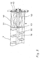
- einen Verweiler (Ausschnitt).
- Ein Konditionierer 1 beinhaltet einen Dosierer 2 (Schneckendosierer), einen Mischer 3 und im konkreten Fall zwei Verweiler 4, die übereinander angeordnet sind und ein Konditioniermodul bilden. Der Mischer 3 und die Verweiler 4 weisen jeweils gleichartige Stirnplatten 5 bzw. 6 auf, über die auch die Modulanordnung erfolgt.
- Die Produktführung erfolgt über die entsprechenden Produktzuführöffnungen 7, 9 bzw. Produktabführöffnungen 8, 10. Über die Produktabführöffnung 10 des unteren Verweilers 4 erfolgt die Übergabe des Produkts in eine Würfelpresse. Der Dosierer 2 ist an der Produktzuführöffnung 7 des Mischers 3 angeflanscht.
- Der Mischer 3 weist einen schnelllaufenden Rotor zur intensiven Produktdurchmischung mit Dampf, Gasen und/oder Flüssigkeiten auf. Der Verweiler 4 ist hingegen mit einem langsam laufenden Rotor versehen. Im Verweiler 4 wird das erhitzte, gemischte Produkt über eine vorbestimmte Zeit auf einer definierten Temperatur gehalten.
- Mischer 3 und Verweiler 4 weisen dicht verschliessbare Öffnungen 11 bzw. 12 im jeweiligen Mantel 13 bzw. 14 auf. Die Mäntel 13 bzw. 14 sind rohrförmig und wie auch die Öffnungen 11, 12 und Stirnplatten 5, 6 vollständig mit Heizmatten und Isolationsmitteln belegt. Bevorzugt sind die Innenseiten der Mäntel 13, 14, einschliesslich der Produktübergabeöffnungen (Bezugszeichen 7 bis 10) vollkommen glatt.
- Mischer 3 und Verweiler 4 enthalten Rotoren 15 bzw. 16 mit Arbeitselementen. Diese können schneckenförmig oder paddelförmig ausgebildet sein. Paddel sind überdeckend ausgebildet, was ein Anbacken von Produkt an der Gehäuseinnenwand von Mischer 3 oder Verteiler 4 unterbindet. Aussen sind an den Rotoren 15, 16 Antriebseinheiten 19, 20 angeflanscht. Die Rotoren 15, 16 bestehen aus gleichartigen Segmenten, so dass ein leichter Austausch gegeben ist und nur wenig Platz für Ausbau und Wechsel benötigt wird. Die Rotorwellen sind bevorzugt als Hohlwellen ausgebildet.
- Für einen Wechsel eines Rotors 15, 16 o. a. genügt es, die Antriebseinheit 19 bzw. 20 resp. eine Stirnplatte 5, 6 zu entfernen und den Rotor nach lösen der gegenüber liegenden Lagerung herauszuziehen. Die Antriebe 19, 20 können wahlweise rechts oder links angeordnet sein.
- Sämtliche Bauteile sind bevorzugt kompatibel und kombinierbar.
- Der/die Verweiler 4 weist gegenüber dem Mischer 3 und dem Dosierer 2 geringere Drehzahlen des Rotors auf, so dass für einen kontinuierlichen Betrieb das Fassungsvermögen der Einzelaggregate abzustimmen ist.
- Der Rotor 16 des Verweilers 4 ist im Bereich der Produktabführöffnung mit schraubenförmig verdrehten, bandförmigen Misch- und Förderelementen (Leitblech 40) ausgerüstet, die einen kontinuierlichen und hohen, gleichmässigen Produktfluss zur Würfelpresse 30 ermöglichen. Insbesondere soll durch eine leichte Überhebung des Produkts dessen Bewegung verzerrt und ein pulsieren desselben gedämpft werden.
- Die Leitbleche 40 sind zwischen Rädern 41, 42 angeordnet und bilden mit diesen bevorzugt eine Baugruppe. Die Räder 41, 42 weisen nicht dargestellte Speichen auf, die einen ungehinderten Produktfluss ermöglichen. Die Räder 41, 42 sind mittels üblicher Buchsen 43 auf dem Rotor 16 des Verweilers 4 angeordnet.
- Die Ausführung der Leitbleche 40 und deren Anzahl kann mit der Kapazität bzw. Bauform des Konditionierers 1 variieren. Minimal sind 4 Leitbleche vorgesehen, möglich sind auch bis ca. 16 derartige Leitbleche 40.
- Bedarfsweise können auf der Rotorwelle noch zusätzliche Paddel vorgesehen sein.
- Die Pellets werden nach verlassen der Würfelpresse in üblicher Weise in einem Kühlergekühlt und anschliessend in üblicher Weise weiteren Stationen zugeführt.
-
- 1.
- Konditionierer
- 2.
- Dosierer
- 3.
- Mischer
- 4.
- Verweiler
- 5.
- Stirnplatte
- 6.
- Stirnplatte
- 7.
- Produktzuführöffnung
- 8.
- Produktabführöffnung
- 9.
- Produktzuführöffnung
- 10.
- Produktabführöffnung
- 11.
- Öffnung
- 12.
- Öffnung
- 13.
- Mantel
- 14.
- Mantel
- 15.
- Rotor
- 16.
- Rotor
- 19.
- Antriebseinheit
- 20.
- Antriebseinheit
- 41
- Rad
- 42
- Rad
- 43
- Buchse
- 44
- Paddel
Claims (9)
- Konditionierer (1) mit mindestens einem Aggregat (4) zum Mischen von Produkten, wobei das Aggregat (4) einen Mantel (14) aufweist, in dem ein drehbarer Rotor (16) mit Arbeitselementen (44) angeordnet ist, wobei die Arbeitselemente (44) schneckenförmig oder paddelförmig ausgebildet sind und wobei das Aggregat ein Verweiler (4) mit einem Rotor (16) ist und der Verweiler (4) im Bereich einer Produktabführöffnung (10) mit Misch- und Förderelementen (40) versehen ist, dadurch gekennzeichnet, dass die Misch- und Förderelemente bandförmige Leitbleche (40) sind, die zwischen radförmigen Elementen (41, 42) angeordnet und über diese mit dem Rotor (16) des Verweilers (4) verbunden sind.
- Konditionierer nach Anspruch 1, dadurch gekennzeichnet, dass die Misch- und Förderelemente (40) schraubenförmig verdreht angeordneten sind.
- Konditionierer nach Anspruch 2, dadurch gekennzeichnet, dass 4 bis 16 Leitbleche (40), bevorzugt 12 Leitbleche (40) angeordnet sind.
- Konditionierer nach Anspruch 1, dadurch gekennzeichnet, dass ein Mischer (3) dem Verweiler (4) vorgeschaltet ist und Mischer (3) und Verweiler (4) an beiden Stirnseiten durch Stirnplatten (5, 6) verschlossen sind.
- Konditionierer nach Anspruch 4, dadurch gekenntzeichnet, dass die Aggregate (3, 4) mindestens an den Stirnplatten (5, 6) einer Stirnseite so verbindbar sind, dass eine Modulanordnung gegeben ist.
- Konditionierer nach einem der Ansprüche 4 oder 5, dadurch gekennzeichnet, dass die Rotoren (15, 16) von Mischer (3) und Verweiler (4) aus je mindestens einem Segment bestehen und bevorzugt als Hohlwellen ausgebildete Rotorwellen aufweisen.
- Konditionierer nach mindestens einem der Ansprüche 4 bis 6, dadurch gekennzeichnet, dass zumindest Mäntel (13, 14) von Mischer (3) und Verweiler (4) sowie deren Stirnplatten (5, 6) und Produktübergabeöffnungen (7-10) mit Heizmitteln bzw. wärmeisolierenden Mitteln versehen sind.
- Konditionierer nach Anspruch 4, dadurch gekennzeichnet, dass dem Mischer (3) ein Dosierer (2) vorangestellt ist und diese Aggregate so miteinander verbunden sind, dass ein Produktdurchlauf gegeben ist.
- Konditionierer nach Anspruch 8, dadurch gekennzeichnet, dass dem mindestens einem Verweiler (4) eine Presse oder ein Expander nachgeordnet ist.
Applications Claiming Priority (5)
| Application Number | Priority Date | Filing Date | Title |
|---|---|---|---|
| DE10213737A DE10213737A1 (de) | 2002-03-26 | 2002-03-26 | Konditionierer |
| DE10213737 | 2002-03-26 | ||
| DE2002130817 DE10230817A1 (de) | 2002-07-08 | 2002-07-08 | Konditionierer |
| DE10230817 | 2002-07-08 | ||
| EP03744753A EP1478892B1 (de) | 2002-03-26 | 2003-03-26 | Konditionierer |
Related Parent Applications (1)
| Application Number | Title | Priority Date | Filing Date |
|---|---|---|---|
| EP03744753.9 Division | 2003-03-26 |
Publications (3)
| Publication Number | Publication Date |
|---|---|
| EP1489371A2 EP1489371A2 (de) | 2004-12-22 |
| EP1489371A3 EP1489371A3 (de) | 2011-03-30 |
| EP1489371B1 true EP1489371B1 (de) | 2012-12-26 |
Family
ID=28455545
Family Applications (2)
| Application Number | Title | Priority Date | Filing Date |
|---|---|---|---|
| EP04019766A Expired - Lifetime EP1489371B1 (de) | 2002-03-26 | 2003-03-26 | Konditionierer |
| EP03744753A Expired - Lifetime EP1478892B1 (de) | 2002-03-26 | 2003-03-26 | Konditionierer |
Family Applications After (1)
| Application Number | Title | Priority Date | Filing Date |
|---|---|---|---|
| EP03744753A Expired - Lifetime EP1478892B1 (de) | 2002-03-26 | 2003-03-26 | Konditionierer |
Country Status (11)
| Country | Link |
|---|---|
| EP (2) | EP1489371B1 (de) |
| JP (1) | JP2005528093A (de) |
| CN (1) | CN100526777C (de) |
| AT (1) | ATE299578T1 (de) |
| AU (1) | AU2003210117A1 (de) |
| BR (1) | BR0307805B1 (de) |
| DE (1) | DE50300766D1 (de) |
| DK (2) | DK1489371T3 (de) |
| NO (1) | NO20044278L (de) |
| RU (1) | RU2319913C2 (de) |
| WO (1) | WO2003081155A1 (de) |
Families Citing this family (6)
| Publication number | Priority date | Publication date | Assignee | Title |
|---|---|---|---|---|
| DE102004055792A1 (de) * | 2004-11-18 | 2006-05-24 | Bühler AG | Verfahren zur Herstellung von Futtermitteln |
| DE102006002199B4 (de) * | 2006-01-16 | 2011-03-10 | Bühler AG | Verfahren und Vorrichtung zur kontinuierlichen, hygienisierenden Behandlung von Futtermitteln |
| DE102006026511A1 (de) * | 2006-06-06 | 2007-12-13 | Bühler AG | Verfahren zur Herstellung einer Futterzusammensetzung für Rinder |
| CN104997144B (zh) * | 2015-08-26 | 2017-03-29 | 通威股份有限公司 | 一种罗非鱼颗粒饲料的生产工艺 |
| CN107140764B (zh) * | 2017-05-30 | 2018-07-03 | 浙江华腾牧业有限公司 | 一种饲料搅拌器的污水循环再利用设备及其使用方法 |
| CN112438414A (zh) * | 2019-08-29 | 2021-03-05 | 布勒(常州)机械有限公司 | 一种粉料热处理工艺和装置 |
Family Cites Families (7)
| Publication number | Priority date | Publication date | Assignee | Title |
|---|---|---|---|---|
| US1449280A (en) * | 1922-03-24 | 1923-03-20 | Carrellvernon B Ginn | Sterilizer and seed drier |
| US1690753A (en) * | 1926-04-17 | 1928-11-06 | Edw Renneburg & Sons Co | Combination cooker drier |
| US1793638A (en) * | 1928-04-26 | 1931-02-24 | Rowton Harold Stanley | Construction of fish-meal plants |
| GB1106445A (en) * | 1966-11-22 | 1968-03-20 | Ralston Purina Co | Preparation of food |
| SU991115A1 (ru) * | 1979-06-15 | 1983-01-23 | Головной Экспериментально-Конструкторский Институт По Машинам Для Переработки Травы И Соломы | Барабан дл сушки сельскохоз йственных продуктов |
| US4659299A (en) * | 1985-10-23 | 1987-04-21 | California Pellet Mill Company | Mash pelleting apparatus |
| DK0610789T3 (da) * | 1993-02-10 | 2001-04-23 | Buehler Ag | Indretning til eliminering af bakterier og kim |
-
2003
- 2003-03-26 EP EP04019766A patent/EP1489371B1/de not_active Expired - Lifetime
- 2003-03-26 DK DK04019766.7T patent/DK1489371T3/da active
- 2003-03-26 AU AU2003210117A patent/AU2003210117A1/en not_active Abandoned
- 2003-03-26 DK DK03744753T patent/DK1478892T3/da active
- 2003-03-26 WO PCT/CH2003/000198 patent/WO2003081155A1/de not_active Ceased
- 2003-03-26 AT AT03744753T patent/ATE299578T1/de not_active IP Right Cessation
- 2003-03-26 RU RU2004131562/06A patent/RU2319913C2/ru not_active IP Right Cessation
- 2003-03-26 BR BRPI0307805-1A patent/BR0307805B1/pt active IP Right Grant
- 2003-03-26 EP EP03744753A patent/EP1478892B1/de not_active Expired - Lifetime
- 2003-03-26 JP JP2003578843A patent/JP2005528093A/ja not_active Withdrawn
- 2003-03-26 CN CNB03806944XA patent/CN100526777C/zh not_active Expired - Lifetime
- 2003-03-26 DE DE50300766T patent/DE50300766D1/de not_active Expired - Lifetime
-
2004
- 2004-10-08 NO NO20044278A patent/NO20044278L/no not_active Application Discontinuation
Also Published As
| Publication number | Publication date |
|---|---|
| DK1478892T3 (da) | 2005-11-14 |
| EP1478892A1 (de) | 2004-11-24 |
| CN100526777C (zh) | 2009-08-12 |
| EP1478892B1 (de) | 2005-07-13 |
| WO2003081155A1 (de) | 2003-10-02 |
| RU2004131562A (ru) | 2005-08-27 |
| EP1489371A2 (de) | 2004-12-22 |
| ATE299578T1 (de) | 2005-07-15 |
| BR0307805B1 (pt) | 2014-07-22 |
| RU2319913C2 (ru) | 2008-03-20 |
| JP2005528093A (ja) | 2005-09-22 |
| DE50300766D1 (de) | 2005-08-18 |
| BR0307805A (pt) | 2004-12-21 |
| AU2003210117A1 (en) | 2003-10-08 |
| DK1489371T3 (da) | 2013-02-25 |
| NO20044278L (no) | 2004-10-08 |
| CN1643319A (zh) | 2005-07-20 |
| EP1489371A3 (de) | 2011-03-30 |
Similar Documents
| Publication | Publication Date | Title |
|---|---|---|
| EP2154980B1 (de) | Pasteurisierungsanlage zum pasteuriseren von tierfutter | |
| EP0853491B1 (de) | Mischkneter | |
| EP2114465B1 (de) | Pasteurisierungsvorrichtung mit integrierter wärmepumpe und verfahren hierzu | |
| DE69223816T2 (de) | Kontinuierlicher, unterteilter mixer | |
| EP2255869B1 (de) | Horizontalmischer | |
| DE2124010C3 (de) | Wärmeaustauscher zum Erhitzen, Trocknen oder Abkühlen | |
| DE102013022092A1 (de) | Trocknungsbehälter für Schüttgüter, insbesondere Kunststoffgranulat, sowie Verfahren zum Trocknen und/oder Kristallisieren von Schüttgut | |
| EP2114176B1 (de) | Vorrichtung und verfahren zur wärmebehandlung eines schüttfähigen pflanzlichen gutes | |
| EP1478892B1 (de) | Konditionierer | |
| EP0610789B1 (de) | Vorrichtung zur Eliminierung von Bakterien und Keimen | |
| US2611590A (en) | Method and apparatus for stage kneading | |
| DE10213737A1 (de) | Konditionierer | |
| EP1164876B1 (de) | Verfahren und vorrichtung zur hygienisierenden, thermischen behandlung von mehl | |
| US7396151B2 (en) | Conditioner | |
| DE20220986U1 (de) | Konditionierer | |
| DE19530806C2 (de) | Sterilisiergerät und Gerät zum Herstellen eines Flüssigproduktes | |
| EP1285586B1 (de) | Verfahren und Vorrichtung zur kontinuierlichen Förderung von Süsswarenmassen | |
| DE10230817A1 (de) | Konditionierer | |
| EP4354060B1 (de) | Querstromwärmetauscher zur thermischen behandlung von granulatförmigen stoffen | |
| EP0940087B1 (de) | Anlage zur Herstellung von Schokoladenartikeln mit mehreren Kühlabschnitten | |
| DE2402940A1 (de) | Vorrichtung zum mischen, kuehlen und erwaermen von fluids | |
| DE1751728A1 (de) | Waermetauscher fuer die Behandlung von hochviskosen Fluessigkeiten,vorzugsweise Loesungen von Viskose | |
| CH686993A5 (de) | Verfahren zur thermischen Behandlung von fliessfaehigem Gut in fester Form, Mischvorrichtung zu dessen Durchfuehrung und danach hergestelltes Gut. | |
| DE528628C (de) | Verfahren und Vorrichtung zur Herstellung von Kaese | |
| DE102006002199B4 (de) | Verfahren und Vorrichtung zur kontinuierlichen, hygienisierenden Behandlung von Futtermitteln |
Legal Events
| Date | Code | Title | Description |
|---|---|---|---|
| PUAI | Public reference made under article 153(3) epc to a published international application that has entered the european phase |
Free format text: ORIGINAL CODE: 0009012 |
|
| AC | Divisional application: reference to earlier application |
Ref document number: 1478892 Country of ref document: EP Kind code of ref document: P |
|
| AK | Designated contracting states |
Kind code of ref document: A2 Designated state(s): AT BE BG CH CY CZ DE DK EE ES FI FR GB GR HU IE IT LI LU MC NL PT RO SE SI SK TR |
|
| AX | Request for extension of the european patent |
Extension state: AL LT LV MK |
|
| RIN1 | Information on inventor provided before grant (corrected) |
Inventor name: HANIMANN, PHILIPP Inventor name: HERMSMEYER, ANDREA |
|
| PUAL | Search report despatched |
Free format text: ORIGINAL CODE: 0009013 |
|
| AK | Designated contracting states |
Kind code of ref document: A3 Designated state(s): AT BE BG CH CY CZ DE DK EE ES FI FR GB GR HU IE IT LI LU MC NL PT RO SE SI SK TR |
|
| AX | Request for extension of the european patent |
Extension state: AL LT LV MK |
|
| RTI1 | Title (correction) |
Free format text: CONDITIONER |
|
| 17P | Request for examination filed |
Effective date: 20110614 |
|
| 17Q | First examination report despatched |
Effective date: 20110922 |
|
| AKX | Designation fees paid |
Designated state(s): AT BE BG CH CY CZ DE DK EE ES FI FR GB GR HU IE IT LI LU MC NL PT RO SE SI SK TR |
|
| GRAP | Despatch of communication of intention to grant a patent |
Free format text: ORIGINAL CODE: EPIDOSNIGR1 |
|
| GRAS | Grant fee paid |
Free format text: ORIGINAL CODE: EPIDOSNIGR3 |
|
| GRAA | (expected) grant |
Free format text: ORIGINAL CODE: 0009210 |
|
| AC | Divisional application: reference to earlier application |
Ref document number: 1478892 Country of ref document: EP Kind code of ref document: P |
|
| AK | Designated contracting states |
Kind code of ref document: B1 Designated state(s): AT BE BG CH CY CZ DE DK EE ES FI FR GB GR HU IE IT LI LU MC NL PT RO SE SI SK TR |
|
| REG | Reference to a national code |
Ref country code: GB Ref legal event code: FG4D Free format text: NOT ENGLISH |
|
| REG | Reference to a national code |
Ref country code: CH Ref legal event code: EP |
|
| REG | Reference to a national code |
Ref country code: AT Ref legal event code: REF Ref document number: 590700 Country of ref document: AT Kind code of ref document: T Effective date: 20130115 |
|
| REG | Reference to a national code |
Ref country code: DK Ref legal event code: T3 |
|
| REG | Reference to a national code |
Ref country code: DE Ref legal event code: R096 Ref document number: 50314644 Country of ref document: DE Effective date: 20130228 |
|
| REG | Reference to a national code |
Ref country code: NL Ref legal event code: T3 |
|
| PG25 | Lapsed in a contracting state [announced via postgrant information from national office to epo] |
Ref country code: SE Free format text: LAPSE BECAUSE OF FAILURE TO SUBMIT A TRANSLATION OF THE DESCRIPTION OR TO PAY THE FEE WITHIN THE PRESCRIBED TIME-LIMIT Effective date: 20121226 Ref country code: FI Free format text: LAPSE BECAUSE OF FAILURE TO SUBMIT A TRANSLATION OF THE DESCRIPTION OR TO PAY THE FEE WITHIN THE PRESCRIBED TIME-LIMIT Effective date: 20121226 |
|
| PG25 | Lapsed in a contracting state [announced via postgrant information from national office to epo] |
Ref country code: SI Free format text: LAPSE BECAUSE OF FAILURE TO SUBMIT A TRANSLATION OF THE DESCRIPTION OR TO PAY THE FEE WITHIN THE PRESCRIBED TIME-LIMIT Effective date: 20121226 Ref country code: GR Free format text: LAPSE BECAUSE OF FAILURE TO SUBMIT A TRANSLATION OF THE DESCRIPTION OR TO PAY THE FEE WITHIN THE PRESCRIBED TIME-LIMIT Effective date: 20130327 |
|
| PG25 | Lapsed in a contracting state [announced via postgrant information from national office to epo] |
Ref country code: EE Free format text: LAPSE BECAUSE OF FAILURE TO SUBMIT A TRANSLATION OF THE DESCRIPTION OR TO PAY THE FEE WITHIN THE PRESCRIBED TIME-LIMIT Effective date: 20121226 Ref country code: CZ Free format text: LAPSE BECAUSE OF FAILURE TO SUBMIT A TRANSLATION OF THE DESCRIPTION OR TO PAY THE FEE WITHIN THE PRESCRIBED TIME-LIMIT Effective date: 20121226 Ref country code: ES Free format text: LAPSE BECAUSE OF FAILURE TO SUBMIT A TRANSLATION OF THE DESCRIPTION OR TO PAY THE FEE WITHIN THE PRESCRIBED TIME-LIMIT Effective date: 20130406 Ref country code: SK Free format text: LAPSE BECAUSE OF FAILURE TO SUBMIT A TRANSLATION OF THE DESCRIPTION OR TO PAY THE FEE WITHIN THE PRESCRIBED TIME-LIMIT Effective date: 20121226 Ref country code: BG Free format text: LAPSE BECAUSE OF FAILURE TO SUBMIT A TRANSLATION OF THE DESCRIPTION OR TO PAY THE FEE WITHIN THE PRESCRIBED TIME-LIMIT Effective date: 20130326 Ref country code: CY Free format text: LAPSE BECAUSE OF FAILURE TO SUBMIT A TRANSLATION OF THE DESCRIPTION OR TO PAY THE FEE WITHIN THE PRESCRIBED TIME-LIMIT Effective date: 20121226 |
|
| PG25 | Lapsed in a contracting state [announced via postgrant information from national office to epo] |
Ref country code: PT Free format text: LAPSE BECAUSE OF FAILURE TO SUBMIT A TRANSLATION OF THE DESCRIPTION OR TO PAY THE FEE WITHIN THE PRESCRIBED TIME-LIMIT Effective date: 20130426 Ref country code: RO Free format text: LAPSE BECAUSE OF FAILURE TO SUBMIT A TRANSLATION OF THE DESCRIPTION OR TO PAY THE FEE WITHIN THE PRESCRIBED TIME-LIMIT Effective date: 20121226 |
|
| BERE | Be: lapsed |
Owner name: BUHLER A.G. Effective date: 20130331 |
|
| PG25 | Lapsed in a contracting state [announced via postgrant information from national office to epo] |
Ref country code: MC Free format text: LAPSE BECAUSE OF NON-PAYMENT OF DUE FEES Effective date: 20130331 |
|
| REG | Reference to a national code |
Ref country code: CH Ref legal event code: PL |
|
| PLBE | No opposition filed within time limit |
Free format text: ORIGINAL CODE: 0009261 |
|
| STAA | Information on the status of an ep patent application or granted ep patent |
Free format text: STATUS: NO OPPOSITION FILED WITHIN TIME LIMIT |
|
| GBPC | Gb: european patent ceased through non-payment of renewal fee |
Effective date: 20130326 |
|
| 26N | No opposition filed |
Effective date: 20130927 |
|
| PG25 | Lapsed in a contracting state [announced via postgrant information from national office to epo] |
Ref country code: IT Free format text: LAPSE BECAUSE OF FAILURE TO SUBMIT A TRANSLATION OF THE DESCRIPTION OR TO PAY THE FEE WITHIN THE PRESCRIBED TIME-LIMIT Effective date: 20121226 |
|
| REG | Reference to a national code |
Ref country code: IE Ref legal event code: MM4A |
|
| REG | Reference to a national code |
Ref country code: DE Ref legal event code: R097 Ref document number: 50314644 Country of ref document: DE Effective date: 20130927 |
|
| PG25 | Lapsed in a contracting state [announced via postgrant information from national office to epo] |
Ref country code: GB Free format text: LAPSE BECAUSE OF NON-PAYMENT OF DUE FEES Effective date: 20130326 Ref country code: IE Free format text: LAPSE BECAUSE OF NON-PAYMENT OF DUE FEES Effective date: 20130326 Ref country code: LI Free format text: LAPSE BECAUSE OF NON-PAYMENT OF DUE FEES Effective date: 20130331 Ref country code: CH Free format text: LAPSE BECAUSE OF NON-PAYMENT OF DUE FEES Effective date: 20130331 Ref country code: BE Free format text: LAPSE BECAUSE OF NON-PAYMENT OF DUE FEES Effective date: 20130331 |
|
| REG | Reference to a national code |
Ref country code: AT Ref legal event code: MM01 Ref document number: 590700 Country of ref document: AT Kind code of ref document: T Effective date: 20130326 |
|
| PG25 | Lapsed in a contracting state [announced via postgrant information from national office to epo] |
Ref country code: AT Free format text: LAPSE BECAUSE OF NON-PAYMENT OF DUE FEES Effective date: 20130326 |
|
| PG25 | Lapsed in a contracting state [announced via postgrant information from national office to epo] |
Ref country code: TR Free format text: LAPSE BECAUSE OF FAILURE TO SUBMIT A TRANSLATION OF THE DESCRIPTION OR TO PAY THE FEE WITHIN THE PRESCRIBED TIME-LIMIT Effective date: 20121226 |
|
| PG25 | Lapsed in a contracting state [announced via postgrant information from national office to epo] |
Ref country code: LU Free format text: LAPSE BECAUSE OF NON-PAYMENT OF DUE FEES Effective date: 20130326 Ref country code: HU Free format text: LAPSE BECAUSE OF FAILURE TO SUBMIT A TRANSLATION OF THE DESCRIPTION OR TO PAY THE FEE WITHIN THE PRESCRIBED TIME-LIMIT; INVALID AB INITIO Effective date: 20030326 |
|
| REG | Reference to a national code |
Ref country code: FR Ref legal event code: PLFP Year of fee payment: 14 |
|
| REG | Reference to a national code |
Ref country code: FR Ref legal event code: PLFP Year of fee payment: 15 |
|
| REG | Reference to a national code |
Ref country code: FR Ref legal event code: PLFP Year of fee payment: 16 |
|
| PGFP | Annual fee paid to national office [announced via postgrant information from national office to epo] |
Ref country code: DK Payment date: 20220322 Year of fee payment: 20 Ref country code: DE Payment date: 20220322 Year of fee payment: 20 |
|
| PGFP | Annual fee paid to national office [announced via postgrant information from national office to epo] |
Ref country code: NL Payment date: 20220322 Year of fee payment: 20 Ref country code: FR Payment date: 20220323 Year of fee payment: 20 |
|
| REG | Reference to a national code |
Ref country code: DE Ref legal event code: R071 Ref document number: 50314644 Country of ref document: DE |
|
| REG | Reference to a national code |
Ref country code: DK Ref legal event code: EUP Expiry date: 20230326 |
|
| REG | Reference to a national code |
Ref country code: NL Ref legal event code: MK Effective date: 20230325 |
|
| P01 | Opt-out of the competence of the unified patent court (upc) registered |
Effective date: 20230523 |