EP1489370A1 - Regeleinheit für einen Kühlkreislauf - Google Patents
Regeleinheit für einen Kühlkreislauf Download PDFInfo
- Publication number
- EP1489370A1 EP1489370A1 EP04253518A EP04253518A EP1489370A1 EP 1489370 A1 EP1489370 A1 EP 1489370A1 EP 04253518 A EP04253518 A EP 04253518A EP 04253518 A EP04253518 A EP 04253518A EP 1489370 A1 EP1489370 A1 EP 1489370A1
- Authority
- EP
- European Patent Office
- Prior art keywords
- compressor
- discharge pressure
- refrigeration cycle
- control unit
- limit value
- Prior art date
- Legal status (The legal status is an assumption and is not a legal conclusion. Google has not performed a legal analysis and makes no representation as to the accuracy of the status listed.)
- Granted
Links
Images


Classifications
-
- F—MECHANICAL ENGINEERING; LIGHTING; HEATING; WEAPONS; BLASTING
- F25—REFRIGERATION OR COOLING; COMBINED HEATING AND REFRIGERATION SYSTEMS; HEAT PUMP SYSTEMS; MANUFACTURE OR STORAGE OF ICE; LIQUEFACTION SOLIDIFICATION OF GASES
- F25B—REFRIGERATION MACHINES, PLANTS OR SYSTEMS; COMBINED HEATING AND REFRIGERATION SYSTEMS; HEAT PUMP SYSTEMS
- F25B27/00—Machines, plants or systems, using particular sources of energy
-
- B—PERFORMING OPERATIONS; TRANSPORTING
- B60—VEHICLES IN GENERAL
- B60H—ARRANGEMENTS OF HEATING, COOLING, VENTILATING OR OTHER AIR-TREATING DEVICES SPECIALLY ADAPTED FOR PASSENGER OR GOODS SPACES OF VEHICLES
- B60H1/00—Heating, cooling or ventilating [HVAC] devices
- B60H1/32—Cooling devices
- B60H1/3204—Cooling devices using compression
- B60H1/3205—Control means therefor
- B60H1/3211—Control means therefor for increasing the efficiency of a vehicle refrigeration cycle
-
- F—MECHANICAL ENGINEERING; LIGHTING; HEATING; WEAPONS; BLASTING
- F25—REFRIGERATION OR COOLING; COMBINED HEATING AND REFRIGERATION SYSTEMS; HEAT PUMP SYSTEMS; MANUFACTURE OR STORAGE OF ICE; LIQUEFACTION SOLIDIFICATION OF GASES
- F25B—REFRIGERATION MACHINES, PLANTS OR SYSTEMS; COMBINED HEATING AND REFRIGERATION SYSTEMS; HEAT PUMP SYSTEMS
- F25B49/00—Arrangement or mounting of control or safety devices
- F25B49/02—Arrangement or mounting of control or safety devices for compression type machines, plants or systems
- F25B49/022—Compressor control arrangements
-
- B—PERFORMING OPERATIONS; TRANSPORTING
- B60—VEHICLES IN GENERAL
- B60H—ARRANGEMENTS OF HEATING, COOLING, VENTILATING OR OTHER AIR-TREATING DEVICES SPECIALLY ADAPTED FOR PASSENGER OR GOODS SPACES OF VEHICLES
- B60H1/00—Heating, cooling or ventilating [HVAC] devices
- B60H1/32—Cooling devices
- B60H2001/3236—Cooling devices information from a variable is obtained
- B60H2001/3239—Cooling devices information from a variable is obtained related to flow
- B60H2001/3242—Cooling devices information from a variable is obtained related to flow of a refrigerant
-
- B—PERFORMING OPERATIONS; TRANSPORTING
- B60—VEHICLES IN GENERAL
- B60H—ARRANGEMENTS OF HEATING, COOLING, VENTILATING OR OTHER AIR-TREATING DEVICES SPECIALLY ADAPTED FOR PASSENGER OR GOODS SPACES OF VEHICLES
- B60H1/00—Heating, cooling or ventilating [HVAC] devices
- B60H1/32—Cooling devices
- B60H2001/3236—Cooling devices information from a variable is obtained
- B60H2001/3248—Cooling devices information from a variable is obtained related to pressure
- B60H2001/325—Cooling devices information from a variable is obtained related to pressure of the refrigerant at a compressing unit
-
- B—PERFORMING OPERATIONS; TRANSPORTING
- B60—VEHICLES IN GENERAL
- B60H—ARRANGEMENTS OF HEATING, COOLING, VENTILATING OR OTHER AIR-TREATING DEVICES SPECIALLY ADAPTED FOR PASSENGER OR GOODS SPACES OF VEHICLES
- B60H1/00—Heating, cooling or ventilating [HVAC] devices
- B60H1/32—Cooling devices
- B60H2001/3236—Cooling devices information from a variable is obtained
- B60H2001/3255—Cooling devices information from a variable is obtained related to temperature
- B60H2001/3261—Cooling devices information from a variable is obtained related to temperature of the air at an evaporating unit
-
- B—PERFORMING OPERATIONS; TRANSPORTING
- B60—VEHICLES IN GENERAL
- B60H—ARRANGEMENTS OF HEATING, COOLING, VENTILATING OR OTHER AIR-TREATING DEVICES SPECIALLY ADAPTED FOR PASSENGER OR GOODS SPACES OF VEHICLES
- B60H1/00—Heating, cooling or ventilating [HVAC] devices
- B60H1/32—Cooling devices
- B60H2001/3236—Cooling devices information from a variable is obtained
- B60H2001/3266—Cooling devices information from a variable is obtained related to the operation of the vehicle
-
- B—PERFORMING OPERATIONS; TRANSPORTING
- B60—VEHICLES IN GENERAL
- B60H—ARRANGEMENTS OF HEATING, COOLING, VENTILATING OR OTHER AIR-TREATING DEVICES SPECIALLY ADAPTED FOR PASSENGER OR GOODS SPACES OF VEHICLES
- B60H1/00—Heating, cooling or ventilating [HVAC] devices
- B60H1/32—Cooling devices
- B60H2001/3269—Cooling devices output of a control signal
- B60H2001/327—Cooling devices output of a control signal related to a compressing unit
- B60H2001/3275—Cooling devices output of a control signal related to a compressing unit to control the volume of a compressor
-
- F—MECHANICAL ENGINEERING; LIGHTING; HEATING; WEAPONS; BLASTING
- F25—REFRIGERATION OR COOLING; COMBINED HEATING AND REFRIGERATION SYSTEMS; HEAT PUMP SYSTEMS; MANUFACTURE OR STORAGE OF ICE; LIQUEFACTION SOLIDIFICATION OF GASES
- F25B—REFRIGERATION MACHINES, PLANTS OR SYSTEMS; COMBINED HEATING AND REFRIGERATION SYSTEMS; HEAT PUMP SYSTEMS
- F25B2500/00—Problems to be solved
- F25B2500/19—Calculation of parameters
-
- F—MECHANICAL ENGINEERING; LIGHTING; HEATING; WEAPONS; BLASTING
- F25—REFRIGERATION OR COOLING; COMBINED HEATING AND REFRIGERATION SYSTEMS; HEAT PUMP SYSTEMS; MANUFACTURE OR STORAGE OF ICE; LIQUEFACTION SOLIDIFICATION OF GASES
- F25B—REFRIGERATION MACHINES, PLANTS OR SYSTEMS; COMBINED HEATING AND REFRIGERATION SYSTEMS; HEAT PUMP SYSTEMS
- F25B2600/00—Control issues
- F25B2600/02—Compressor control
-
- F—MECHANICAL ENGINEERING; LIGHTING; HEATING; WEAPONS; BLASTING
- F25—REFRIGERATION OR COOLING; COMBINED HEATING AND REFRIGERATION SYSTEMS; HEAT PUMP SYSTEMS; MANUFACTURE OR STORAGE OF ICE; LIQUEFACTION SOLIDIFICATION OF GASES
- F25B—REFRIGERATION MACHINES, PLANTS OR SYSTEMS; COMBINED HEATING AND REFRIGERATION SYSTEMS; HEAT PUMP SYSTEMS
- F25B2700/00—Sensing or detecting of parameters; Sensors therefor
- F25B2700/21—Temperatures
- F25B2700/2106—Temperatures of fresh outdoor air
-
- F—MECHANICAL ENGINEERING; LIGHTING; HEATING; WEAPONS; BLASTING
- F25—REFRIGERATION OR COOLING; COMBINED HEATING AND REFRIGERATION SYSTEMS; HEAT PUMP SYSTEMS; MANUFACTURE OR STORAGE OF ICE; LIQUEFACTION SOLIDIFICATION OF GASES
- F25B—REFRIGERATION MACHINES, PLANTS OR SYSTEMS; COMBINED HEATING AND REFRIGERATION SYSTEMS; HEAT PUMP SYSTEMS
- F25B2700/00—Sensing or detecting of parameters; Sensors therefor
- F25B2700/21—Temperatures
- F25B2700/2117—Temperatures of an evaporator
- F25B2700/21171—Temperatures of an evaporator of the fluid cooled by the evaporator
- F25B2700/21173—Temperatures of an evaporator of the fluid cooled by the evaporator at the outlet
-
- F—MECHANICAL ENGINEERING; LIGHTING; HEATING; WEAPONS; BLASTING
- F25—REFRIGERATION OR COOLING; COMBINED HEATING AND REFRIGERATION SYSTEMS; HEAT PUMP SYSTEMS; MANUFACTURE OR STORAGE OF ICE; LIQUEFACTION SOLIDIFICATION OF GASES
- F25B—REFRIGERATION MACHINES, PLANTS OR SYSTEMS; COMBINED HEATING AND REFRIGERATION SYSTEMS; HEAT PUMP SYSTEMS
- F25B2700/00—Sensing or detecting of parameters; Sensors therefor
- F25B2700/21—Temperatures
- F25B2700/2117—Temperatures of an evaporator
- F25B2700/21175—Temperatures of an evaporator of the refrigerant at the outlet of the evaporator
Definitions
- the present invention relates to a control unit for a refrigeration cycle having a variable displacement compressor controlled by an external control signal, and, more specifically, to a refrigeration cycle control unit which can control a discharge pressure of the compressor by controlling a displacement of the compressor by estimating the discharge pressure of the compressor.
- a refrigeration cycle control unit in which, in a refrigeration cycle having an external signal control type variable displacement compressor, a high-pressure side pressure of the refrigeration cycle, that is, a discharge pressure of the compressor, is estimated, thereby controlling the discharge pressure at an optimum value. Further, it would be desirable to make it unnecessary to detect a high-pressure side pressure of the refrigeration cycle with a sensor, etc., by estimating a discharge pressure of the compressor, thereby making a more inexpensive system.
- a refrigeration cycle control unit comprises a suction pressure estimation or detection means for estimating or detecting a physical value with a correlation with a suction pressure of a compressor and a pressure difference estimation or detection means for estimating or detecting a physical value with a correlation with a pressure difference between a discharge pressure and the suction pressure of the compressor, for a refrigeration cycle having the compressor, which is a variable displacement compressor a displacement of which is controlled by an external control signal, a condenser of refrigerant, an evaporator of refrigerant, and is characterized in that the control unit comprises a discharge pressure estimation means for estimating the discharge pressure of the compressor by referring to the physical value with a correlation with the suction pressure of the compressor estimated or detected by the suction pressure estimation or detection means, and the physical value with a correlation with a pressure difference between the discharge pressure and the suction pressure of the compressor estimated or detected by the pressure difference estimation or detection means. Namely, without providing a pressure detection sensor, the discharge pressure of the compressor is estimated from the physical value
- a refrigeration cycle control unit comprises a suction pressure estimation or detection means for estimating or detecting a physical value with a correlation with a suction pressure of a compressor and an input signal calculation means for calculating an input signal to a compressor with a correlation with a pressure difference between a discharge pressure and the suction pressure of the compressor, for a refrigeration cycle having the compressor, which is a variable displacement compressor a displacement of which is controlled by controlling the pressure difference between the discharge pressure and the suction pressure of the compressor by an external control signal, a condenser of refrigerant, an evaporator of refrigerant, and is characterized in that the control unit comprises a discharge pressure estimation means for estimating the discharge pressure of the compressor by referring to the physical value with a correlation with the suction pressure of the compressor estimated or detected by the suction pressure estimation or detection means, and a displacement control signal as the input signal with a correlation with the pressure difference between the discharge pressure and the suction pressure of the compressor calculated by the input signal calculation means.
- control unit further comprises a compressor displacement control means for controlling a displacement of the variable displacement compressor, and a discharge pressure limit value calculation means for calculating an upper limit value of the discharge pressure of the compressor, and the discharge pressure of the compressor may be adjusted by controlling the displacement of the compressor by the compressor displacement control means, referring to the discharge pressure of the compressor estimated by the discharge pressure estimation means and the discharge pressure limit value of the compressor calculated by the discharge pressure limit value calculation means.
- the displacement of the compressor or the pressure difference between the discharge pressure and the suction pressure of the compressor may be controlled so as to be decreased by the compressor displacement control means.
- the discharge pressure of the compressor estimated by the discharge pressure estimation means decreases to a value of a predetermined value A, which is lower than the discharge pressure limit value, or less, the control for decreasing the displacement of the compressor or the pressure difference between the discharge pressure and the suction pressure of the compressor is cancelled, and control of the control unit is returned to a usual control.
- control unit further comprises a compressor stop means for interrupting a displacement control signal to the compressor or stopping drive of the compressor, and referring to the discharge pressure limit value of the compressor calculated by the discharge pressure limit value calculation means and the discharge pressure of the compressor estimated by the discharge pressure estimation means, immediately after or after a predetermined time expires after the estimated discharge pressure exceeds the discharge pressure limit value, the displacement control signal to the compressor is interrupted or the drive of the compressor is stopped by the compressor stop means.
- the control for interrupting the displacement control signal to the compressor or stopping the drive of the compressor by the compressor stop means is cancelled, and control of the control unit is returned to a usual control.
- the discharge pressure of the compressor is controlled by controlling the displacement of the compressor comparing the permissible discharge pressure 1 and the estimated discharge pressure or referring to a deviation therebetween.
- the control unit further comprises a compressor stop means for interrupting a displacement control signal to the compressor or stopping drive of the compressor, and a discharge pressure detection means for detecting the discharge pressure of the compressor, and when a detected discharge pressure exceeds the discharge pressure limit value, the compressor stop means interrupts the displacement control signal or stops drive of the compressor.
- control unit further comprises a compressor rotational speed detection or estimation means for detecting or estimating a physical value having a correlation with a rotational speed of the compressor, and the discharge pressure limit value calculation means calculates the discharge pressure limit value by referring to the rotational speed of the compressor detected or estimated by the compressor rotational speed detection or estimation means.
- control unit further comprises a refrigeration cycle load detection means for detecting a thermal load of the refrigeration cycle
- discharge pressure limit value calculation means calculates the discharge pressure limit value by referring to the thermal load of the refrigeration cycle detected by the refrigeration cycle load detection means in addition to the rotational speed of the compressor.
- the following thermal load of the refrigeration cycle can be employed. Namely, a structure may be employed wherein the refrigeration cycle is a refrigeration cycle provided in an air conditioning system for vehicles, and the refrigeration cycle load detection means detects the thermal load from any combination of an outside air temperature and a vehicle running speed, or a condensation temperature of refrigerant, or an outside air sensor.
- the control unit further comprises a blower sending air to the evaporator
- the suction pressure estimation means estimates a suction pressure by referring to an evaporator temperature and/or a physical value having a correlation with a refrigerant flow rate.
- the evaporator temperature may be a temperature of air immediately after passing through the evaporator, or a temperature of refrigerant near the evaporator, or a temperature at a position between fins of the evaporator, or a temperature at a surface of a refrigerant tube from an entrance of the evaporator to a suction port of the compressor.
- a refrigerant pressure is determined univocally from a refrigerant temperature in the evaporator. Therefore, it is possible to estimate a refrigerant pressure in the evaporator by determining a refrigerant temperature by detecting the above-described evaporator temperature. Further, in an actual refrigeration cycle, there occurs a pressure reduction of refrigerant due to a pressure loss in a circuit from the evaporator to a compressor. Since this pressure loss becomes greater as a refrigerant flow rate increases, it is possible to estimate the pressure loss by detecting the refrigerant flow rate.
- the refrigerant suction pressure of the compressor has a close correlation with the refrigerant temperature and the refrigerant flow rate in the evaporator, and by detecting or estimating these two values, it becomes possible to adequately estimate the refrigerant suction pressure.
- the refrigerant suction pressure is estimated by using the following equation.
- Ps' a • Gr + b • Teva + c
- Ps' an estimated value of refrigerant suction pressure
- Gr a refrigerant flow rate
- Teva an air temperature at an evaporator exit
- a, b, c a constant determined by an examination.
- the refrigeration cycle control unit it is possible to adequately estimate the discharge pressure of the compressor, and to properly protect the compressor by controlling the discharge pressure of the compressor at a preferable value or within a preferable range based on the estimated value. Further, because the discharge pressure is estimated, it is not necessary to detect a high-pressure side pressure of the refrigeration cycle by a sensor, etc., and the whole of the system may be simplified and a more inexpensive system may be made.
- FIG. 1 depicts an air conditioning system for vehicles having a refrigeration cycle control unit according to an embodiment of the present invention.
- an air conditioning system for vehicles 1 has an air duct 2 opening toward a vehicle interior, and a blower 6 is provided at an upstream position in air duct 2. Blower 6 sends air sucked from outside air introduction port 4 and inside air introduction port which are adjusted by outside air/inside air switching damper 3.
- An evaporator 7 is provided as a cooler for cooling the sent air at a position downstream of blower 6, and at a position downstream thereof, a heater core as a heater 8 is provided. To heater 8, for example, engine cooling water is circulated.
- An air mixing damper 10 which is adjusted in opening degree by an air mixing damper actuator 9, is disposed at a position immediately upstream of heater 8.
- the temperature-controlled air is discharged through respective air discharge ports 14, 15 and 16 such as DEF, VENT and FOOT mode air discharge ports having respective dampers 11, 12 and 13.
- Refrigeration cycle 17 is structured as a refrigerant circuit connected via refrigerant tubes.
- a variable displacement compressor 18 the displacement of which is controlled by an external displacement control signal
- a condenser 19 which condenses high-temperature and high-pressure refrigerant compressed by compressor 18,
- a receiver 20 which separates the condensed refrigerant into gas and liquid phases
- an expansion valve 21 which reduces in pressure the refrigerant sent from receiver 20 and expand the refrigerant
- evaporator 7 which evaporates the refrigerant sent from expansion valve 21 and cools air sent through air duct 2 by heat exchange with the air, are disposed in this order, and the refrigerant from evaporator 7 is sucked into compressor 18 and served to be compressed again.
- compressor 18 is driven by an engine 22 for driving a vehicle via a clutch. On/off operation of this clutch is carried out via a clutch controller 30, and in this embodiment, a pressure switch 31 is provided in a clutch control signal circuit from a main controller 23.
- Main controller 23 is a controller for air conditioning, and a refrigeration cycle control unit according to the present invention is incorporated into main controller 23.
- the displacement control system of compressor 18 is different from a conventional compressor suction pressure control system, and it is a pressure difference control type-displacement control system controlling a pressure difference between a discharge pressure and a suction pressure of compressor 18, and an external displacement control signal ( ⁇ PdPs) is given from main controller 23 as an input signal having a correlation with the above-described pressure difference. Further, in this compressor, when the displacement control signal ( ⁇ PdPs) is set at a certain value ( ⁇ PdPsmin), the displacement is controlled at minimum. Fig.
- ⁇ PdPs displacement control signal
- ⁇ PdPsmin and ⁇ PdPs1 are displacement control signals for the following control.
- ⁇ PdPsmin a displacement control signal controlling the compressor at a minimum displacement
- ⁇ PdPs1 a displacement control signal controlling the compressor at a certain pressure difference
- a clutch is provided for connecting/disconnecting the drive force transmission from a drive source for the compressor, and a clutch signal for controlling this connection/disconnection of the clutch is sent from main controller 23.
- the control according to the present invention can be applied to a system having no clutch.
- an evaporator exit air temperature sensor 24 is provided at a position downstream of evaporator 7, and a signal of detected evaporator exit air temperature Teva is sent to main controller 23. Further, a detection signal of a vehicle interior temperature Tin from vehicle interior temperature sensor 25, a detection signal of an outside air temperature Tamb from outside air temperature sensor 26, and as needed, a detection signal of a sunshine amount from sunshine sensor 27, a signal 28 of an engine rotational speed Ne (or a compressor rotational speed) and a signal BLV of a voltage of a motor 29 for driving blower 6 (a blower voltage), are sent to main controller 23, respectively. From main controller 23, an opening degree control signal of air mixing damper 10 is sent to air mixing damper actuator 9, and a clutch control signal is sent to clutch controller 30.
- control is carried out as shown in Fig. 3.
- a displacement control is carried out by setting the evaporator exit air temperature control as a usual control in this embodiment. Further, it is possible to avoid an inconvenience such as a trouble of the compressor due to an increase in high-pressure side pressure by performing the discharge pressure control of the refrigeration cycle.
- a calculation value of displacement control signal for evaporator temperature control is calculated from signals of evaporator exit air temperature target value Toff and evaporator exit air temperature Teva by an evaporator exit air temperature control means. For example, the calculation is carried out by the following proportional integral calculation by using a deviation between evaporator exit air temperature target value Toff and evaporator exit air temperature Teva. In this embodiment, this control is set as a usual control.
- SIGte P (proportional calculation) + I (integral calculation) Where, P and I are calculated as follows.
- P Kp x (Toff - Teva)
- I Kp/Ki x (Toff - Teva) + I n-1
- control is an ability control of an evaporator in this embodiment, except this, as usual controls there are an ability control of a condenser, a torque control of a compressor, etc.
- estimation or calculation of an input information used for discharge pressure control of a compressor is carried out, for example, as follows.
- the suction pressure of a compressor is estimated by using an evaporator temperature and a refrigerant flow rate as aforementioned.
- Ps f(Teva, Gr) (in this embodiment)
- Ps f (Te, Gr) (as another embodiment)
- Te an evaporator temperature
- Teva an evaporator exit air temperature
- Gr a refrigerant flow rate
- evaporator temperature Te As the evaporator temperature Te, as aforementioned, a temperature of air immediately after passing through an evaporator (namely, the above-described evaporator exit air temperature Teva), or a temperature of refrigerant near the evaporator, or a temperature at a position between fins of the evaporator, or a temperature at a surface of a refrigerant tube from an entrance of the evaporator to a suction port of a compressor.
- the discharge pressure of a compressor is estimated by using a compressor refrigerant suction pressure (Ps) and a pressure difference ( ⁇ PdPs) between the refrigerant suction pressure and a discharge pressure.
- Ps refrigerant suction pressure
- ⁇ PdPs pressure difference
- ⁇ PdPs has a correlation with a displacement control signal of an external control signal type compressor, and the estimation can be carried out by the displacement control signal.
- the discharge pressure limit value is calculated by using an engine rotational speed (Ne) or a compressor rotational speed (Nc), an outside air temperature (Tamb), a vehicle speed (VS), a condensation temperature (Tcond), etc.
- Pdu1 f(Ne) (in this embodiment)
- Pdu1 f (Ne, Tamb)
- Pdu1 f (Ne, Tamb, VS)
- Pdu1 f (Tcond)
- the permissible discharge pressure of a compressor is calculated, for example, by subtracting a predetermined value (B) from the discharge pressure limit value (Pdu1).
- Pdh Pdul - B
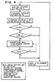
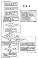
- the control of compressor discharge pressure in the refrigeration cycle is carried out, for example, by the flows as shown in Figs. 4 to 6 based on the above-described estimated and calculated information.
- This compressor small displacement control is a control for achieving a predetermined pressure difference by controlling the compressor displacement control signal ( ⁇ PdPs) at ⁇ PdPs1 based on Fig. 2.
- ⁇ PdPs compressor displacement control signal
- the compressor small displacement control is carried out immediately after the estimated discharge pressure (Pd) exceeds the discharge pressure limit value (Pdu1) or after the predetermined time T expires, instead of such a compressor small displacement control, the following controls may be employed as other examples.
- a discharge pressure restriction control No. 2 shown in Fig. 5 estimation of suction pressure, estimation of discharge pressure, calculation of discharge pressure limit value and calculation of permissible discharge pressure are carried out, and referring to a deviation between the permissible discharge pressure (Pdh) and the estimated discharge pressure, the following integral calculation is carried out and a displacement control signal for controlling a discharge pressure (SIGp) is calculated, and the discharge pressure of the compressor is controlled by outputting the calculated displacement control signal.
- a discharge pressure restriction control No. 3 shown in Fig. 6 estimation of suction pressure, estimation of discharge pressure, calculation of discharge pressure limit value and calculation of permissible discharge pressure are carried out, and when, for example, a pressure switch provided to a tube in a refrigerant circuit detects a predetermined discharge pressure (Pdoff), the connection between a compressor and a drive source thereof is interrupted. Further, when the pressure switch does not operate, referring to a deviation between the permissible discharge pressure (Pdh) and the estimated discharge pressure, proportional or/and integral calculation is carried out, a displacement control signal for controlling a discharge pressure is calculated, and the discharge pressure of the compressor is controlled by outputting the calculated displacement control signal.
- Pdh permissible discharge pressure
- this compressor small displacement control is a control for achieving a predetermined pressure difference by controlling the compressor displacement control signal ( ⁇ PdPs) at ⁇ PdPs1 based on Fig. 2. Also in this embodiment, although the compressor small displacement control is carried out immediately after the estimated discharge pressure (Pd) exceeds the discharge pressure limit value (Pdu1) or after the predetermined time T expires, instead of such a compressor small displacement control, the following controls may be employed as other examples.
Landscapes
- Engineering & Computer Science (AREA)
- Physics & Mathematics (AREA)
- Mechanical Engineering (AREA)
- Thermal Sciences (AREA)
- General Engineering & Computer Science (AREA)
- Control Of Positive-Displacement Pumps (AREA)
- Air-Conditioning For Vehicles (AREA)
- Air Conditioning Control Device (AREA)
Applications Claiming Priority (2)
| Application Number | Priority Date | Filing Date | Title |
|---|---|---|---|
| JP2003175705 | 2003-06-20 | ||
| JP2003175705A JP2005009794A (ja) | 2003-06-20 | 2003-06-20 | 冷凍サイクル制御装置 |
Publications (2)
| Publication Number | Publication Date |
|---|---|
| EP1489370A1 true EP1489370A1 (de) | 2004-12-22 |
| EP1489370B1 EP1489370B1 (de) | 2007-01-24 |
Family
ID=33410997
Family Applications (1)
| Application Number | Title | Priority Date | Filing Date |
|---|---|---|---|
| EP04253518A Expired - Lifetime EP1489370B1 (de) | 2003-06-20 | 2004-06-11 | Regeleinheit für einen Kühlkreislauf |
Country Status (4)
| Country | Link |
|---|---|
| EP (1) | EP1489370B1 (de) |
| JP (1) | JP2005009794A (de) |
| CN (1) | CN100538218C (de) |
| DE (1) | DE602004004443T2 (de) |
Cited By (6)
| Publication number | Priority date | Publication date | Assignee | Title |
|---|---|---|---|---|
| EP1887292A1 (de) * | 2005-05-30 | 2008-02-13 | Daikin Industries, Ltd. | Feuchtigkeitsregler |
| EP1995095A1 (de) * | 2007-05-22 | 2008-11-26 | Delphi Technologies, Inc. | Steuerverfahren für einen Verdichter mit variabler Verdrängung in einer leistungsoptimierten Klimaanlage |
| US8042347B2 (en) | 2007-05-28 | 2011-10-25 | Denso Corporation | Compressor inlet pressure estimation apparatus for refrigeration cycle system |
| US20120324927A1 (en) * | 2010-02-24 | 2012-12-27 | Kenichi Suzuki | Air conditioning system for vehicles |
| US9885508B2 (en) | 2011-12-28 | 2018-02-06 | Carrier Corporation | Discharge pressure calculation from torque in an HVAC system |
| US10471793B2 (en) | 2016-10-12 | 2019-11-12 | Ford Global Technologies, Llc | Seat mounts for side load spring on a twist beam axle |
Families Citing this family (21)
| Publication number | Priority date | Publication date | Assignee | Title |
|---|---|---|---|---|
| JP4375437B2 (ja) * | 2007-05-28 | 2009-12-02 | 株式会社デンソー | 冷凍サイクル装置のコンプレッサの吸入圧力推定装置 |
| JP5360006B2 (ja) | 2009-07-16 | 2013-12-04 | 株式会社デンソー | 車両用空調装置 |
| FR2951669B1 (fr) * | 2009-10-26 | 2011-10-28 | Valeo Systemes Thermiques | Procede de controle du fonctionnement d'une boucle de climatisation d'un vehicule |
| FR2969044B1 (fr) * | 2010-12-17 | 2012-12-28 | Renault Sa | Systeme et procede de commande d'un systeme d'air climatise pour vehicule automobile |
| US20130094972A1 (en) * | 2011-10-18 | 2013-04-18 | Ford Global Technologies, Llc | Climate Thermal Load Based Minimum Flow Rate Water Pump Control |
| JP5859299B2 (ja) * | 2011-12-15 | 2016-02-10 | 株式会社ヴァレオジャパン | 圧縮機の駆動トルク推定装置及びこれに用いる凝縮器 |
| CN102767886B (zh) * | 2012-07-26 | 2014-12-03 | 宁波奥克斯电气有限公司 | 判断多联式空调机组的冷媒是否适量的方法 |
| US10451325B2 (en) | 2012-08-24 | 2019-10-22 | Carrier Corporation | Transcritical refrigerant vapor compression system high side pressure control |
| IN2014MU01491A (de) * | 2014-04-01 | 2015-10-09 | Emerson Climate Technologies | |
| US10371426B2 (en) | 2014-04-01 | 2019-08-06 | Emerson Climate Technologies, Inc. | System and method of controlling a variable-capacity compressor |
| WO2015191553A1 (en) | 2014-06-09 | 2015-12-17 | Emerson Climate Technologies, Inc. | System and method for controlling a variable-capacity compressor |
| US10507707B2 (en) * | 2015-06-12 | 2019-12-17 | Ford Global Technologies, Llc | Controlling HVAC compressor speed in a vehicle |
| CN105466093B (zh) * | 2015-11-17 | 2017-12-19 | 广东美的制冷设备有限公司 | 压缩机的排气压力和回气压力的虚拟检测方法及装置 |
| CN105299845B (zh) * | 2015-11-20 | 2018-03-13 | 广东美的制冷设备有限公司 | 空调系统运行参数虚拟检测方法及装置 |
| EP3414499B1 (de) * | 2016-02-10 | 2021-07-07 | Carrier Corporation | Leistungsmanagement für co2-transportkälteanlage |
| CN105841413B (zh) * | 2016-03-29 | 2018-06-26 | 广东美的制冷设备有限公司 | 空调器控制方法及装置 |
| CN110733314A (zh) * | 2018-07-18 | 2020-01-31 | 广东威灵汽车部件有限公司 | 汽车空调压缩机控制方法及装置 |
| CN110422189B (zh) * | 2019-08-27 | 2020-05-12 | 石家庄国祥运输设备有限公司 | 轨道车辆空调机组中压缩机故障的在线预测方法 |
| CN112146227B (zh) * | 2020-08-31 | 2022-04-12 | 珠海格力电器股份有限公司 | 压力检测开关、空调控制方法、装置、空调及存储介质 |
| CN114992925A (zh) * | 2021-03-02 | 2022-09-02 | 广东美的暖通设备有限公司 | 压缩机的控制方法、装置、设备、存储介质及制冷系统 |
| CN113007862B (zh) * | 2021-04-20 | 2022-07-12 | 宁波奥克斯电气股份有限公司 | 吸气侧压力确定方法、模块、空调控制方法、装置和多联机空调 |
Citations (7)
| Publication number | Priority date | Publication date | Assignee | Title |
|---|---|---|---|---|
| US4841736A (en) * | 1987-06-29 | 1989-06-27 | Kabushiki Kaisha Toyoda Jidoshokki Seisakusho | Method for controlling the operation of a variable displacement refrigerant compressor for a car air-conditioner |
| US5172563A (en) * | 1990-06-20 | 1992-12-22 | Zexel Corporation | Apparatus for controlling automobile air-conditioner |
| JPH11201596A (ja) * | 1998-01-14 | 1999-07-30 | Matsushita Electric Ind Co Ltd | 冷凍サイクル装置の圧力検出手段および冷凍サイクル装置 |
| EP1162419A1 (de) * | 2000-06-05 | 2001-12-12 | Denso Corporation | Heisswasserversorgungssystem mit Wärmepumpenkreislauf |
| US20030051495A1 (en) * | 2001-09-17 | 2003-03-20 | Hiromi Ohta | Vehicle air conditioning system |
| WO2003036184A1 (fr) * | 2001-10-25 | 2003-05-01 | Zexel Valeo Climate Control Corporation | Dispositif de commande d'un compresseur a deplacement variable et dispositif de commande a deplacement variable d'un cycle de refrigeration |
| EP1367344A2 (de) * | 2002-05-30 | 2003-12-03 | Praxair Technology, Inc. | Verfahren zum Betreiben einer überkritischen Kälteanlage |
-
2003
- 2003-06-20 JP JP2003175705A patent/JP2005009794A/ja active Pending
-
2004
- 2004-06-11 EP EP04253518A patent/EP1489370B1/de not_active Expired - Lifetime
- 2004-06-11 DE DE602004004443T patent/DE602004004443T2/de not_active Expired - Lifetime
- 2004-06-18 CN CNB200410059298XA patent/CN100538218C/zh not_active Expired - Fee Related
Patent Citations (7)
| Publication number | Priority date | Publication date | Assignee | Title |
|---|---|---|---|---|
| US4841736A (en) * | 1987-06-29 | 1989-06-27 | Kabushiki Kaisha Toyoda Jidoshokki Seisakusho | Method for controlling the operation of a variable displacement refrigerant compressor for a car air-conditioner |
| US5172563A (en) * | 1990-06-20 | 1992-12-22 | Zexel Corporation | Apparatus for controlling automobile air-conditioner |
| JPH11201596A (ja) * | 1998-01-14 | 1999-07-30 | Matsushita Electric Ind Co Ltd | 冷凍サイクル装置の圧力検出手段および冷凍サイクル装置 |
| EP1162419A1 (de) * | 2000-06-05 | 2001-12-12 | Denso Corporation | Heisswasserversorgungssystem mit Wärmepumpenkreislauf |
| US20030051495A1 (en) * | 2001-09-17 | 2003-03-20 | Hiromi Ohta | Vehicle air conditioning system |
| WO2003036184A1 (fr) * | 2001-10-25 | 2003-05-01 | Zexel Valeo Climate Control Corporation | Dispositif de commande d'un compresseur a deplacement variable et dispositif de commande a deplacement variable d'un cycle de refrigeration |
| EP1367344A2 (de) * | 2002-05-30 | 2003-12-03 | Praxair Technology, Inc. | Verfahren zum Betreiben einer überkritischen Kälteanlage |
Non-Patent Citations (1)
| Title |
|---|
| PATENT ABSTRACTS OF JAPAN vol. 1999, no. 12 29 October 1999 (1999-10-29) * |
Cited By (11)
| Publication number | Priority date | Publication date | Assignee | Title |
|---|---|---|---|---|
| EP1887292A1 (de) * | 2005-05-30 | 2008-02-13 | Daikin Industries, Ltd. | Feuchtigkeitsregler |
| EP1887292A4 (de) * | 2005-05-30 | 2009-04-08 | Daikin Ind Ltd | Feuchtigkeitsregler |
| AU2006253454B2 (en) * | 2005-05-30 | 2009-09-24 | Daikin Industries, Ltd. | Humidity controller |
| EP1995095A1 (de) * | 2007-05-22 | 2008-11-26 | Delphi Technologies, Inc. | Steuerverfahren für einen Verdichter mit variabler Verdrängung in einer leistungsoptimierten Klimaanlage |
| US8042347B2 (en) | 2007-05-28 | 2011-10-25 | Denso Corporation | Compressor inlet pressure estimation apparatus for refrigeration cycle system |
| US20120324927A1 (en) * | 2010-02-24 | 2012-12-27 | Kenichi Suzuki | Air conditioning system for vehicles |
| EP2540541A1 (de) * | 2010-02-24 | 2013-01-02 | Sanden Corporation | Klimaanlagenvorrichtung für ein fahrzeug |
| EP2540541A4 (de) * | 2010-02-24 | 2013-08-28 | Sanden Corp | Klimaanlagenvorrichtung für ein fahrzeug |
| US9885508B2 (en) | 2011-12-28 | 2018-02-06 | Carrier Corporation | Discharge pressure calculation from torque in an HVAC system |
| US10619903B2 (en) | 2011-12-28 | 2020-04-14 | Carrier Corporation | Discharge pressure calculation from torque in an HVAC system |
| US10471793B2 (en) | 2016-10-12 | 2019-11-12 | Ford Global Technologies, Llc | Seat mounts for side load spring on a twist beam axle |
Also Published As
| Publication number | Publication date |
|---|---|
| CN1573261A (zh) | 2005-02-02 |
| CN100538218C (zh) | 2009-09-09 |
| EP1489370B1 (de) | 2007-01-24 |
| JP2005009794A (ja) | 2005-01-13 |
| DE602004004443D1 (de) | 2007-03-15 |
| DE602004004443T2 (de) | 2007-11-15 |
Similar Documents
| Publication | Publication Date | Title |
|---|---|---|
| EP1489370B1 (de) | Regeleinheit für einen Kühlkreislauf | |
| US6978632B2 (en) | Air conditioning system for vehicles | |
| EP1700725A1 (de) | Kraftfahrzeugklimaanlage | |
| US6523361B2 (en) | Air conditioning systems | |
| US6681582B2 (en) | Vapor compression type refrigeration apparatus including leak detection and method for detecting refrigerant leaks | |
| US7891204B2 (en) | Refrigeration cycle device for vehicle | |
| US20070028633A1 (en) | Air Conditioning Systems For Vehicles | |
| JP3356142B2 (ja) | 冷凍サイクル装置 | |
| US7775059B2 (en) | Air conditioner | |
| EP1489369A1 (de) | Einheit in einer Klimaanlage, zur Berechnung des Saugdruckes des Kompressors | |
| EP1491375A2 (de) | Einheit zur Berechnung der Kompressorarbeit und Kontrolleinheit zur deren Verwendung | |
| EP1717073A1 (de) | Fahrzeugklimaanlage | |
| US20080196424A1 (en) | Rear evaporator core freeze protection method | |
| CA2440533C (en) | Air conditioning systems for vehicles, vehicles comprising such air conditioning systems, and methods for driving hybrid compressors of such air conditioning systems | |
| EP1609642A1 (de) | Klimasystem für Fahrzeuge | |
| US20080223058A1 (en) | Air Conditioner | |
| JP2007253901A (ja) | 車両用空調装置 | |
| JP3961107B2 (ja) | 外部制御式可変容量コンプレッサのトルク予測装置およびこれを用いた自動車エンジン制御装置 | |
| US6826919B2 (en) | Vapor-compression refrigerant cycle and lock detection device of compressor | |
| EP1491374A2 (de) | Einheit zur Berechnung des Drehmoments in einem Kühlungskreislauf und Kontrolleinheit zur deren Verwendung | |
| US20070137232A1 (en) | Air conditioner | |
| JP2822764B2 (ja) | 空気調和装置の室外ファンの運転制御装置 | |
| EP1640195A2 (de) | Steuerungseinrichtung | |
| JPH04230415A (ja) | 車両用冷房装置における圧縮機の起動制御方法 |
Legal Events
| Date | Code | Title | Description |
|---|---|---|---|
| PUAI | Public reference made under article 153(3) epc to a published international application that has entered the european phase |
Free format text: ORIGINAL CODE: 0009012 |
|
| AK | Designated contracting states |
Kind code of ref document: A1 Designated state(s): AT BE BG CH CY CZ DE DK EE ES FI FR GB GR HU IE IT LI LU MC NL PL PT RO SE SI SK TR |
|
| AX | Request for extension of the european patent |
Extension state: AL HR LT LV MK |
|
| 17P | Request for examination filed |
Effective date: 20050610 |
|
| AKX | Designation fees paid |
Designated state(s): DE FR |
|
| GRAP | Despatch of communication of intention to grant a patent |
Free format text: ORIGINAL CODE: EPIDOSNIGR1 |
|
| GRAS | Grant fee paid |
Free format text: ORIGINAL CODE: EPIDOSNIGR3 |
|
| GRAA | (expected) grant |
Free format text: ORIGINAL CODE: 0009210 |
|
| AK | Designated contracting states |
Kind code of ref document: B1 Designated state(s): DE FR |
|
| REF | Corresponds to: |
Ref document number: 602004004443 Country of ref document: DE Date of ref document: 20070315 Kind code of ref document: P |
|
| ET | Fr: translation filed | ||
| PLBE | No opposition filed within time limit |
Free format text: ORIGINAL CODE: 0009261 |
|
| STAA | Information on the status of an ep patent application or granted ep patent |
Free format text: STATUS: NO OPPOSITION FILED WITHIN TIME LIMIT |
|
| 26N | No opposition filed |
Effective date: 20071025 |
|
| PGFP | Annual fee paid to national office [announced via postgrant information from national office to epo] |
Ref country code: FR Payment date: 20130618 Year of fee payment: 10 |
|
| PGFP | Annual fee paid to national office [announced via postgrant information from national office to epo] |
Ref country code: DE Payment date: 20140619 Year of fee payment: 11 |
|
| REG | Reference to a national code |
Ref country code: FR Ref legal event code: ST Effective date: 20150227 |
|
| PG25 | Lapsed in a contracting state [announced via postgrant information from national office to epo] |
Ref country code: FR Free format text: LAPSE BECAUSE OF NON-PAYMENT OF DUE FEES Effective date: 20140630 |
|
| REG | Reference to a national code |
Ref country code: DE Ref legal event code: R119 Ref document number: 602004004443 Country of ref document: DE |
|
| PG25 | Lapsed in a contracting state [announced via postgrant information from national office to epo] |
Ref country code: DE Free format text: LAPSE BECAUSE OF NON-PAYMENT OF DUE FEES Effective date: 20160101 |