EP1717073A1 - Fahrzeugklimaanlage - Google Patents
Fahrzeugklimaanlage Download PDFInfo
- Publication number
- EP1717073A1 EP1717073A1 EP05709727A EP05709727A EP1717073A1 EP 1717073 A1 EP1717073 A1 EP 1717073A1 EP 05709727 A EP05709727 A EP 05709727A EP 05709727 A EP05709727 A EP 05709727A EP 1717073 A1 EP1717073 A1 EP 1717073A1
- Authority
- EP
- European Patent Office
- Prior art keywords
- displacement
- value
- compressor
- temperature
- variable displacement
- Prior art date
- Legal status (The legal status is an assumption and is not a legal conclusion. Google has not performed a legal analysis and makes no representation as to the accuracy of the status listed.)
- Withdrawn
Links
Images


Classifications
-
- F—MECHANICAL ENGINEERING; LIGHTING; HEATING; WEAPONS; BLASTING
- F25—REFRIGERATION OR COOLING; COMBINED HEATING AND REFRIGERATION SYSTEMS; HEAT PUMP SYSTEMS; MANUFACTURE OR STORAGE OF ICE; LIQUEFACTION SOLIDIFICATION OF GASES
- F25B—REFRIGERATION MACHINES, PLANTS OR SYSTEMS; COMBINED HEATING AND REFRIGERATION SYSTEMS; HEAT PUMP SYSTEMS
- F25B49/00—Arrangement or mounting of control or safety devices
- F25B49/02—Arrangement or mounting of control or safety devices for compression type machines, plants or systems
- F25B49/022—Compressor control arrangements
-
- B—PERFORMING OPERATIONS; TRANSPORTING
- B60—VEHICLES IN GENERAL
- B60H—ARRANGEMENTS OF HEATING, COOLING, VENTILATING OR OTHER AIR-TREATING DEVICES SPECIALLY ADAPTED FOR PASSENGER OR GOODS SPACES OF VEHICLES
- B60H1/00—Heating, cooling or ventilating [HVAC] devices
- B60H1/32—Cooling devices
- B60H1/3204—Cooling devices using compression
-
- B—PERFORMING OPERATIONS; TRANSPORTING
- B60—VEHICLES IN GENERAL
- B60H—ARRANGEMENTS OF HEATING, COOLING, VENTILATING OR OTHER AIR-TREATING DEVICES SPECIALLY ADAPTED FOR PASSENGER OR GOODS SPACES OF VEHICLES
- B60H1/00—Heating, cooling or ventilating [HVAC] devices
- B60H1/32—Cooling devices
- B60H2001/3236—Cooling devices information from a variable is obtained
- B60H2001/3255—Cooling devices information from a variable is obtained related to temperature
- B60H2001/3261—Cooling devices information from a variable is obtained related to temperature of the air at an evaporating unit
-
- B—PERFORMING OPERATIONS; TRANSPORTING
- B60—VEHICLES IN GENERAL
- B60H—ARRANGEMENTS OF HEATING, COOLING, VENTILATING OR OTHER AIR-TREATING DEVICES SPECIALLY ADAPTED FOR PASSENGER OR GOODS SPACES OF VEHICLES
- B60H1/00—Heating, cooling or ventilating [HVAC] devices
- B60H1/32—Cooling devices
- B60H2001/3269—Cooling devices output of a control signal
- B60H2001/327—Cooling devices output of a control signal related to a compressing unit
-
- F—MECHANICAL ENGINEERING; LIGHTING; HEATING; WEAPONS; BLASTING
- F25—REFRIGERATION OR COOLING; COMBINED HEATING AND REFRIGERATION SYSTEMS; HEAT PUMP SYSTEMS; MANUFACTURE OR STORAGE OF ICE; LIQUEFACTION SOLIDIFICATION OF GASES
- F25B—REFRIGERATION MACHINES, PLANTS OR SYSTEMS; COMBINED HEATING AND REFRIGERATION SYSTEMS; HEAT PUMP SYSTEMS
- F25B2400/00—General features or devices for refrigeration machines, plants or systems, combined heating and refrigeration systems or heat-pump systems, i.e. not limited to a particular subgroup of F25B
- F25B2400/07—Details of compressors or related parts
- F25B2400/075—Details of compressors or related parts with parallel compressors
- F25B2400/0751—Details of compressors or related parts with parallel compressors the compressors having different capacities
-
- F—MECHANICAL ENGINEERING; LIGHTING; HEATING; WEAPONS; BLASTING
- F25—REFRIGERATION OR COOLING; COMBINED HEATING AND REFRIGERATION SYSTEMS; HEAT PUMP SYSTEMS; MANUFACTURE OR STORAGE OF ICE; LIQUEFACTION SOLIDIFICATION OF GASES
- F25B—REFRIGERATION MACHINES, PLANTS OR SYSTEMS; COMBINED HEATING AND REFRIGERATION SYSTEMS; HEAT PUMP SYSTEMS
- F25B2500/00—Problems to be solved
- F25B2500/19—Calculation of parameters
Definitions
- the present invention relates to an air conditioning system for vehicles with a refrigeration cycle having refrigerant compressors, and more specifically, to control of an air conditioning system for vehicles having a variable displacement compressor.
- an object of the present invention is to provide an air conditioning system for vehicles capable of suppressing deterioration of the thermally comfortable feeling of passengers, in an air conditioning for a vehicle wherein a cooler temperature varies greatly by an overshoot in a feedback control when compressor operation is switched.
- an air conditioning system for vehicles comprises compressors different from each other, displacement control system switching means for switching a displacement control system A to a variable displacement control system B with respect to the displacement control system A controlled by a displacement control value "a" among displacement control values "a” and “b” for the compressors different from each other and the variable displacement control system B controlled by the displacement control value "b”, and feedforward displacement value calculation means for the variable displacement control system B for calculating a displacement control value of the variable displacement control system B as an input to a control object so as to obtain a target control displacement after the displacement control system is switched.
- the variable displacement control system B is started based on a feedforward displacement value calculated by the feedforward displacement value calculation means for the variable displacement control system B.
- a structure may be employed wherein the system further comprises an air duct, a blower for sending air into a vehicle interior through the air duct, a cooler connected to the refrigeration cycle for cooling the air sent to the vehicle interior, cooler temperature recognition means for estimating or detecting a physical value having a correlation with a temperature of the cooler or a temperature of air passing through the cooler, target cooler temperature calculation means for calculating a target cooler temperature referring to a refrigeration cycle load, variable displacement compressor feedback displacement value calculation means for calculating a feedback displacement value so as to control the displacement of the variable displacement compressor at a predetermined displacement referring to a deviation between the target cooler temperature and the value recognized as cooler temperature, and time calculation means for calculating a time having a correlation with the refrigeration cycle load, until that the temperature of the cooler or the temperature of air passing through the cooler reaches a predetermined temperature.
- variable displacement compressor after the operation is switched from the compressor to the variable displacement compressor, the variable displacement compressor is started based on the feedforward displacement value calculated by the variable displacement compressor feedforward displacement value calculation means, and after the time calculated by the time calculation means passes, the operation of the variable displacement compressor is controlled based on the feedforward displacement value and the feedback displacement value calculated by the variable displacement compressor feedback displacement value calculation means.
- the variable displacement compressor may be started based on only the feedforward displacement value calculated by the variable displacement compressor feedforward displacement value calculation means without referring to the cooler temperature value recognized by the cooler temperature recognition means.
- a structure may be employed wherein the system further comprises an air duct, a blower for sending air into a vehicle interior through the air duct, a cooler connected to the refrigeration cycle for cooling the air sent to the vehicle interior, and at least one of cooler temperature recognition means for estimating or detecting a physical value having a correlation with a temperature of the cooler or a temperature of air passing through the cooler, outside air temperature recognition means for estimating or detecting a physical value having a correlation with a temperature of outside air, vehicle interior air temperature recognition means for estimating or detecting a physical value having a correlation with a temperature of vehicle interior air, cooler entrance air temperature recognition means for estimating or detecting a physical value having a correlation with a temperature of air at an entrance of the cooler, sunshine amount recognition means for estimating or detecting a physical value having a correlation with an amount of sunshine, blown air amount recognition means for estimating or detecting a physical value having a correlation with an amount of air blown by the blower, target cooler temperature calculation means for calculating a target value of the air
- a load of the refrigeration cycle is estimated or detected by referring to at least one of a cooler temperature recognized value, an outside air temperature recognized value, a vehicle interior air temperature recognized value, a cooler entrance air temperature recognized value, a sunshine amount recognized value, a blown air amount recognized value, a target cooler temperature, and a vehicle running speed recognized value.
- a displacement varying compression mechanism of the variable displacement compressor a displacement varying compression mechanism controlled by a displacement control signal or a displacement varying compression mechanism controlled by rotational speed control may be employed.
- variable displacement compressor when the compressor operation is switched, because the variable displacement compressor is started based on an optimum feedforward displacement value corresponding to a refrigeration cycle load at that time, it is possible to suppress a great variation of the cooler temperature, thereby suppressing a variation of the temperature of air blown into a vehicle interior and the temperature of the vehicle interior.
- the compressor operation when the compressor operation is switched, even in a case where the refrigerant flow rate in the refrigeration cycle varies greatly, the cooler temperature does not vary greatly, the variation in temperature of air blown into a vehicle interior and the vehicle interior may be suppressed, and ultimately, the thermally comfortable feeling of passengers may be prevented from being injured.
- Fig. 1 depicts a schematic equipment disposition diagram of an air conditioning system for vehicles according to an embodiment of the present invention.
- air conditioning system for vehicles 1 depicted in Fig. 1 a blower 4 for sending air sucked through an introduction port 3 for outside air or/and inside air is provided at an upstream position in an air duct 2 opening toward a vehicle interior.
- the blower 4 is driven by a motor 5 for driving the blower.
- An evaporator 6 is provided at a position downstream blower 4 as a cooler for cooling air sent.
- a heater core may be provided at a position downstream evaporator 6 as a heater, although it is not depicted.
- the air having passed through evaporator 6 and having been cooled by the evaporator 6 is blown into a vehicle interior.
- Refrigeration cycle 7 is constructed as a refrigerant circuit in which respective equipment are connected to each other via refrigerant tubes, and in this refrigeration cycle 7, a compressor 11 which can be controlled in displacement by a compressor displacement control signal 9 sent from a main controller 8, and a variable displacement compressor 12 which can be controlled in displacement variably by a variable displacement compressor displacement control signal 10, are provided.
- the drive force may be taken, for example, from an engine of a vehicle, or, it may be driven by a motor and the displacement may be controlled variably by the control of the rotational speed.
- a condenser 14 which condenses the high-temperature and highpressure refrigerant compressed by compressor 11 and to which a cooling fan 13 is provided, a liquid receiver 15 for separating the condensed refrigerant into gas/liquid phases, an expansion valve 16 for reducing in pressure and expanding the refrigerant sent from the liquid receiver 15, and evaporator 6 for evaporating the refrigerant sent from the expansion valve 16 and cooling the air sent through air duct 2 by heat exchange between the refrigerant and the air, are disposed in this order.
- the refrigerant sent from evaporator 6 is sucked to the above-described compressor 11 or the above-described variable displacement compressor 12, and compressed again.
- a signal detected by a cooler exit air temperature sensor 18 provided as an evaporator temperature detection means for detecting a temperature of the evaporator or a temperature of air at an exit of the evaporator (Te), and a signal of an evaporator entrance air temperature (Tein) detected by a cooler entrance air temperature sensor 17, are sent to main controller 8. Further, a signal of a vehicle interior temperature (Tr) detected by a vehicle interior temperature sensor 19, a signal of an outside air temperature (Tamb) detected by an outside air temperature sensor 20, and a signal of a sunshine amount (Rsun) detected by a sunshine sensor 21, are also sent to main controller 8, respectively. Further, a voltage signal (a signal of rotational speed) (Vblw) is outputted from main controller 8 to blower driving motor 5 for controlling the amount of air sent by blower 4.
- Vblw a voltage signal (a signal of rotational speed)
- step S1 main controller 8 reads the information inputted from the aforementioned respective sensors (step S2), a feedforward displacement value (Nmff) for variable displacement compressor 12 is calculated from the information inputted from the respective sensors, for example, by the following equation (step S3).
- Nmff f(Te, Tamb, Tr, Rsun, Tein, Vblw, Tet, Sp) Where, Tet is a target evaporator temperature, and Sp is a vehicle running speed.
- Variable displacement compressor 12 is controlled in starting, based on thus calculated feedforward displacement value (Nmff). Namely, when variable displacement compressor 12 is started, the start is initiated by providing this calculated displacement value (Nmff) as the feedforward displacement value (step S4). In other words, a displacement control target value (Nmt) of variable displacement compressor 12 is set at this feedforward displacement value (Nmff), and the variable displacement compressor 12 is started based on only this feedforward displacement value (Nmff). In a case where variable displacement compressor 12 is driven by a motor, it is applied to the starting control of this motor.
- this feedforward displacement value (Nmff) is calculated as an adequate displacement value in accordance with an actual refrigeration cycle load at that time, even in a case where the refrigerant flow rate greatly varies at the time of switching the compressor operation, it is possible to obtain an adequate displacement value at which the temperature of the cooler (evaporator 6) does not vary greatly, a great variation of the temperature of the air having passed through the cooler and blown into the vehicle interior, ultimately, a great variation of the temperature of the vehicle interior, may be suppressed, and the thermally comfortable feeling of passengers may be prevented from being injured.
- variable displacement compressor 12 After variable displacement compressor 12 is thus started, a variable displacement compressor feedback control delay time (t) is calculated, for example, by the following equation (step S5), and a variable displacement compressor feedback rotational speed (Nmfb) (in a case of rotational speed control) is calculated by the following equation (step S8).
- Kp is a proportional constant (gain)
- Ki an integral constant
- Inn-1 is a previous value.
- step S6 it is determined whether the above-described delay time (t) has passed or not (step S6), and until a predetermined time passes, the variable displacement compressor displacement control is carried out by setting the feedforward displacement value (Nmff) as a target (step S7).
- step S8 the variable displacement compressor displacement control is carried out by setting the sum of the feedforward displacement value (Nmff) and the feedback displacement value (Nmfb) (step S9).
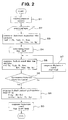
- a general conventional control due to only feedback is shown in Fig. 3.
- the conventional control according to the flow depicted in Fig. 3, when the compressor operation is switched, respective input signals/variables are inputted to a main controller, and the displacement control of a variable displacement compressor is carried out in accordance with refrigeration cycle load. Therefore, as the comparison between the control according to the present invention and the conventional control is shown in Fig. 4, in the conventional control, in a case where the refrigerant flow rate greatly varies after switching of the compressor operation, because an overshoot occurs in the displacement control value by the feedback control for suppressing the variation of the refrigerant flow rate, the refrigerant flow rate is to be varied.
- the temperature of air blown into a vehicle interior and the temperature of the vehicle interior may vary by the temperature variation of a cooler, and there is a case where the thermally comfortable feeling of passengers is injured.
- the control according to the present invention the control according to the embodiment of the present invention
- such a problem can be solved by the feedforward control after switching of the compressor operation, and after a predetermined time passes, adding a feedback control, a desirable control state similar to that in the conventional control can be realized.
- the air conditioning system for vehicles according to the present invention can be suitably applied to any air conditioning system for vehicles with a refrigeration cycle having a compressor and a variable displacement compressor, and in particular, it is suitable to be applied to a case requiring to prevent deterioration of the thermally comfortable feeling of passengers when the compressor operation is switched.
Applications Claiming Priority (2)
| Application Number | Priority Date | Filing Date | Title |
|---|---|---|---|
| JP2004038027A JP4436151B2 (ja) | 2004-02-16 | 2004-02-16 | 車両用空調装置 |
| PCT/JP2005/001661 WO2005077687A1 (ja) | 2004-02-16 | 2005-02-04 | 車両用空調装置 |
Publications (2)
| Publication Number | Publication Date |
|---|---|
| EP1717073A1 true EP1717073A1 (de) | 2006-11-02 |
| EP1717073A4 EP1717073A4 (de) | 2008-05-21 |
Family
ID=34857797
Family Applications (1)
| Application Number | Title | Priority Date | Filing Date |
|---|---|---|---|
| EP05709727A Withdrawn EP1717073A4 (de) | 2004-02-16 | 2005-02-04 | Fahrzeugklimaanlage |
Country Status (4)
| Country | Link |
|---|---|
| US (1) | US20070130975A1 (de) |
| EP (1) | EP1717073A4 (de) |
| JP (1) | JP4436151B2 (de) |
| WO (1) | WO2005077687A1 (de) |
Families Citing this family (5)
| Publication number | Priority date | Publication date | Assignee | Title |
|---|---|---|---|---|
| JP5475501B2 (ja) * | 2010-02-24 | 2014-04-16 | サンデン株式会社 | 車両用空調装置 |
| US20150052916A1 (en) * | 2013-08-23 | 2015-02-26 | Caterpillar Inc. | System and method for controlling air conditioning system |
| MY161113A (en) * | 2013-09-30 | 2017-04-14 | Nissan Motor | Device and method for controlling vehicle |
| US10782056B2 (en) * | 2016-12-01 | 2020-09-22 | Secop Gmbh | Method for operating a variable-speed refrigerant compressor |
| US11674706B2 (en) * | 2021-09-09 | 2023-06-13 | Haier Us Appliance Solutions, Inc. | System and method for operating an air conditioner unit having an auxiliary electric heater |
Citations (4)
| Publication number | Priority date | Publication date | Assignee | Title |
|---|---|---|---|---|
| GB2152246A (en) * | 1983-12-28 | 1985-07-31 | Matsushita Electric Ind Co Ltd | Control apparatus for an air conditioner |
| JPH01111517A (ja) * | 1987-10-26 | 1989-04-28 | Diesel Kiki Co Ltd | 車両用空調制御装置 |
| EP0551008A1 (de) * | 1992-01-07 | 1993-07-14 | Sanden Corporation | Steuervorrichtung zur Verwendung in einer Kraftfahrzeugklimaanlage |
| EP1331115A2 (de) * | 2002-01-23 | 2003-07-30 | Sanden Corporation | Fahrzeugklimaanlage mit einem Hybridkompressor |
Family Cites Families (2)
| Publication number | Priority date | Publication date | Assignee | Title |
|---|---|---|---|---|
| JP3387949B2 (ja) * | 1992-01-07 | 2003-03-17 | サンデン株式会社 | 空調システム |
| JP3936199B2 (ja) * | 2002-01-23 | 2007-06-27 | サンデン株式会社 | 車両用空調装置 |
-
2004
- 2004-02-16 JP JP2004038027A patent/JP4436151B2/ja not_active Expired - Fee Related
-
2005
- 2005-02-04 WO PCT/JP2005/001661 patent/WO2005077687A1/ja not_active Application Discontinuation
- 2005-02-04 EP EP05709727A patent/EP1717073A4/de not_active Withdrawn
- 2005-02-04 US US10/598,009 patent/US20070130975A1/en not_active Abandoned
Patent Citations (4)
| Publication number | Priority date | Publication date | Assignee | Title |
|---|---|---|---|---|
| GB2152246A (en) * | 1983-12-28 | 1985-07-31 | Matsushita Electric Ind Co Ltd | Control apparatus for an air conditioner |
| JPH01111517A (ja) * | 1987-10-26 | 1989-04-28 | Diesel Kiki Co Ltd | 車両用空調制御装置 |
| EP0551008A1 (de) * | 1992-01-07 | 1993-07-14 | Sanden Corporation | Steuervorrichtung zur Verwendung in einer Kraftfahrzeugklimaanlage |
| EP1331115A2 (de) * | 2002-01-23 | 2003-07-30 | Sanden Corporation | Fahrzeugklimaanlage mit einem Hybridkompressor |
Non-Patent Citations (1)
| Title |
|---|
| See also references of WO2005077687A1 * |
Also Published As
| Publication number | Publication date |
|---|---|
| JP2005225418A (ja) | 2005-08-25 |
| EP1717073A4 (de) | 2008-05-21 |
| WO2005077687A1 (ja) | 2005-08-25 |
| US20070130975A1 (en) | 2007-06-14 |
| JP4436151B2 (ja) | 2010-03-24 |
Similar Documents
| Publication | Publication Date | Title |
|---|---|---|
| US6523361B2 (en) | Air conditioning systems | |
| EP1489370B1 (de) | Regeleinheit für einen Kühlkreislauf | |
| US6513341B2 (en) | Air conditioning systems and methods for vehicles | |
| US6978632B2 (en) | Air conditioning system for vehicles | |
| EP1700725A1 (de) | Kraftfahrzeugklimaanlage | |
| EP1749681A2 (de) | Kraftfahrzeugklimaanlage | |
| US7150158B2 (en) | Freezing prevention system for refrigeration device and air conditioner using the same | |
| US7891204B2 (en) | Refrigeration cycle device for vehicle | |
| EP1004828A2 (de) | Verfahren zur Steuerung des Kühlverhaltens einer Klimaanlage | |
| EP1717073A1 (de) | Fahrzeugklimaanlage | |
| US7775059B2 (en) | Air conditioner | |
| JP2005193749A (ja) | 制御装置 | |
| JP2007106260A (ja) | 車両用空調装置 | |
| EP1491375A2 (de) | Einheit zur Berechnung der Kompressorarbeit und Kontrolleinheit zur deren Verwendung | |
| US20080295530A1 (en) | Compressor inlet pressure estimation apparatus for refrigeration cycle system | |
| EP1717075A1 (de) | Klimaanlage | |
| US6823687B2 (en) | Vehicle air conditioner with variable displacement compressor | |
| EP1400689B1 (de) | Fahrzeug-Klimaanlage mit Hybridkompressor | |
| EP1717074A1 (de) | Klimaanlage | |
| EP1491374A2 (de) | Einheit zur Berechnung des Drehmoments in einem Kühlungskreislauf und Kontrolleinheit zur deren Verwendung | |
| EP1640195A2 (de) | Steuerungseinrichtung | |
| JP4482503B2 (ja) | 制御装置 | |
| JP2995940B2 (ja) | 車両用空気調和制御装置 | |
| JP2010047149A (ja) | 車両用空調装置 | |
| JP2006088956A (ja) | 制御装置 |
Legal Events
| Date | Code | Title | Description |
|---|---|---|---|
| PUAI | Public reference made under article 153(3) epc to a published international application that has entered the european phase |
Free format text: ORIGINAL CODE: 0009012 |
|
| 17P | Request for examination filed |
Effective date: 20060907 |
|
| AK | Designated contracting states |
Kind code of ref document: A1 Designated state(s): DE FR |
|
| DAX | Request for extension of the european patent (deleted) | ||
| RBV | Designated contracting states (corrected) |
Designated state(s): DE FR |
|
| A4 | Supplementary search report drawn up and despatched |
Effective date: 20080417 |
|
| RIC1 | Information provided on ipc code assigned before grant |
Ipc: B60H 1/32 20060101AFI20050831BHEP Ipc: F25B 49/02 20060101ALI20080411BHEP |
|
| 17Q | First examination report despatched |
Effective date: 20090430 |
|
| STAA | Information on the status of an ep patent application or granted ep patent |
Free format text: STATUS: THE APPLICATION IS DEEMED TO BE WITHDRAWN |
|
| 18D | Application deemed to be withdrawn |
Effective date: 20090911 |