EP1489325B1 - Ausrücksvorrichtung - Google Patents
Ausrücksvorrichtung Download PDFInfo
- Publication number
- EP1489325B1 EP1489325B1 EP04290822A EP04290822A EP1489325B1 EP 1489325 B1 EP1489325 B1 EP 1489325B1 EP 04290822 A EP04290822 A EP 04290822A EP 04290822 A EP04290822 A EP 04290822A EP 1489325 B1 EP1489325 B1 EP 1489325B1
- Authority
- EP
- European Patent Office
- Prior art keywords
- operating element
- fixing ring
- radial
- ring
- axial
- Prior art date
- Legal status (The legal status is an assumption and is not a legal conclusion. Google has not performed a legal analysis and makes no representation as to the accuracy of the status listed.)
- Expired - Lifetime
Links
- 238000005096 rolling process Methods 0.000 claims description 13
- 238000007789 sealing Methods 0.000 claims description 9
- 210000002105 tongue Anatomy 0.000 description 22
- 238000006073 displacement reaction Methods 0.000 description 4
- 230000014759 maintenance of location Effects 0.000 description 2
- 239000002184 metal Substances 0.000 description 2
- 238000013270 controlled release Methods 0.000 description 1
- 238000005520 cutting process Methods 0.000 description 1
- 230000001627 detrimental effect Effects 0.000 description 1
- 230000000694 effects Effects 0.000 description 1
- 238000005304 joining Methods 0.000 description 1
- 238000004519 manufacturing process Methods 0.000 description 1
- 238000000034 method Methods 0.000 description 1
- 238000000926 separation method Methods 0.000 description 1
- 229920002994 synthetic fiber Polymers 0.000 description 1
Images


Classifications
-
- F—MECHANICAL ENGINEERING; LIGHTING; HEATING; WEAPONS; BLASTING
- F16—ENGINEERING ELEMENTS AND UNITS; GENERAL MEASURES FOR PRODUCING AND MAINTAINING EFFECTIVE FUNCTIONING OF MACHINES OR INSTALLATIONS; THERMAL INSULATION IN GENERAL
- F16D—COUPLINGS FOR TRANSMITTING ROTATION; CLUTCHES; BRAKES
- F16D23/00—Details of mechanically-actuated clutches not specific for one distinct type
- F16D23/12—Mechanical clutch-actuating mechanisms arranged outside the clutch as such
- F16D23/14—Clutch-actuating sleeves or bearings; Actuating members directly connected to clutch-actuating sleeves or bearings
-
- F—MECHANICAL ENGINEERING; LIGHTING; HEATING; WEAPONS; BLASTING
- F16—ENGINEERING ELEMENTS AND UNITS; GENERAL MEASURES FOR PRODUCING AND MAINTAINING EFFECTIVE FUNCTIONING OF MACHINES OR INSTALLATIONS; THERMAL INSULATION IN GENERAL
- F16C—SHAFTS; FLEXIBLE SHAFTS; ELEMENTS OR CRANKSHAFT MECHANISMS; ROTARY BODIES OTHER THAN GEARING ELEMENTS; BEARINGS
- F16C19/00—Bearings with rolling contact, for exclusively rotary movement
- F16C19/02—Bearings with rolling contact, for exclusively rotary movement with bearing balls essentially of the same size in one or more circular rows
- F16C19/14—Bearings with rolling contact, for exclusively rotary movement with bearing balls essentially of the same size in one or more circular rows for both radial and axial load
- F16C19/16—Bearings with rolling contact, for exclusively rotary movement with bearing balls essentially of the same size in one or more circular rows for both radial and axial load with a single row of balls
- F16C19/163—Bearings with rolling contact, for exclusively rotary movement with bearing balls essentially of the same size in one or more circular rows for both radial and axial load with a single row of balls with angular contact
-
- F—MECHANICAL ENGINEERING; LIGHTING; HEATING; WEAPONS; BLASTING
- F16—ENGINEERING ELEMENTS AND UNITS; GENERAL MEASURES FOR PRODUCING AND MAINTAINING EFFECTIVE FUNCTIONING OF MACHINES OR INSTALLATIONS; THERMAL INSULATION IN GENERAL
- F16C—SHAFTS; FLEXIBLE SHAFTS; ELEMENTS OR CRANKSHAFT MECHANISMS; ROTARY BODIES OTHER THAN GEARING ELEMENTS; BEARINGS
- F16C2361/00—Apparatus or articles in engineering in general
- F16C2361/43—Clutches, e.g. disengaging bearing
-
- F—MECHANICAL ENGINEERING; LIGHTING; HEATING; WEAPONS; BLASTING
- F16—ENGINEERING ELEMENTS AND UNITS; GENERAL MEASURES FOR PRODUCING AND MAINTAINING EFFECTIVE FUNCTIONING OF MACHINES OR INSTALLATIONS; THERMAL INSULATION IN GENERAL
- F16D—COUPLINGS FOR TRANSMITTING ROTATION; CLUTCHES; BRAKES
- F16D25/00—Fluid-actuated clutches
- F16D25/08—Fluid-actuated clutches with fluid-actuated member not rotating with a clutching member
- F16D25/082—Fluid-actuated clutches with fluid-actuated member not rotating with a clutching member the line of action of the fluid-actuated members co-inciding with the axis of rotation
- F16D25/083—Actuators therefor
Definitions
- the present invention relates to the field of clutch release stops intended to act on the diaphragm of a clutch, in particular for a motor vehicle.
- the invention is applicable to clutch release bearings comprising a bearing of which one of the rings is rotating and the other ring is fixed.
- the rotating ring Between the rotating ring and the fixed ring are arranged balls regularly distributed in the circumferential direction by means of a cage, the rotating ring being provided with a substantially radial engagement surface intended to come into contact with the fingertips. composing the diaphragm of the clutch.
- An operating element supports the bearing and, under the action of a control member (mechanical, electrical or hydraulic), axially moves the thrust bearing against the diaphragm of the clutch.
- the document WO 02/052163 describes a clutch for a motor vehicle clutch equipped with an axially movable piston and a ring hooked on the piston by means of resilient gripping means having an axial effect.
- One face of the ring bears on an attachment face formed in the piston.
- the clamping means bear on the opposite face of the ring and another attachment face also formed in the piston.
- the resilient clamping means is in the form of an annular fastener provided with lugs projecting in axial bores in the piston which open into radial bores.
- the shape of the piston is therefore relatively complex, which is detrimental in terms of cost.
- the piston, the fastener, the associated spring washer and the ring must be mounted simultaneously, which complicates the assembly process.
- the document FR-A-2 611 244 discloses a clutch release bearing provided with an elastic piece for fixing the non-rotating outer ring and the operating element.
- This part consists of a radial ring from which two diametrically opposed tabs are formed inwardly projecting, comprising a substantially oblique radial portion followed by an essentially axial and also oblique portion, facing away from the rolling elements and towards the outside. outside and ending with an inward folded rim, thus having an overall shape of S. There is no axial portion.
- the tabs are mounted in an opening through a flange of an operating element also provided with an axially elongated sleeve.
- the present invention proposes to remedy these disadvantages.
- the present invention provides a particularly robust and reliable disengagement abutment with elements of relatively simple shape.
- the clutch abutment device is of the type comprising an operating element, and a rolling bearing provided with a non-rotating ring and a rotating race, said rolling bearing being axially secured. of the operating element.
- the device comprises an annular fixing ring provided with an axial annular portion mounted in the operating element and an axially elastic portion axially bearing on the non-rotating ring on the side axially opposite to the operating element, said ring annular being able to maintain the non-rotating ring axially integral with the actuating element while allowing a radial displacement.
- the axial portion of the fixing ring is mounted in a bore of the operating element. This avoids an increase in congestion.
- Such a device is capable of acting on a diaphragm of clutch mechanism.
- the mounting of the stop is easy and convenient.
- the elastic fixing ring can be mounted after the assembly of the bearing, coming to engage with an axial movement.
- the operating element has a simple shape and is therefore robust.
- said fixing ring is in one piece.
- the fixing ring is therefore robust and economical.
- the fixing ring is in direct contact with the operating element.
- the elastic portion is substantially radial and is inclined towards the radial portion of the non-rotating ring.
- the elastic portion may have a convex surface on the side of the non-rotating ring. The convex surface can rub on the non-rotating ring during axial displacements, without excessive wear.
- a plurality of holes are formed in the elastic portion. This increases the axial flexibility of the elastic portion.
- the elastic portion may comprise a plurality of axially elastic tongues.
- the axial portion of the fixing ring comprises fixing tabs on the operating element.
- the fixing ring can be fixed to the operating element by a simple axial movement, the fixing tongues having a certain radial elasticity.
- the free end of the fixing tongues is in contact with a surface integral with the operating element.
- the free end of the fastening tongues is in contact with a substantially radial surface of the operating element.
- Said substantially radial surface may be formed by an annular rib formed in the bore of the operating element.
- the fixing ring may consist of an axial portion mounted in the operating element and supporting resilient tongues, and an axially resilient portion for holding the non-rotating ring.
- the device comprises an additional fixing ring integral with the operating element.
- the additional fixing ring comprises an axial portion and a radial portion in contact with the operating element.
- the radial portion of the additional fixing ring is in contact with the non-rotating ring. This prevents contact between the operating element and the non-rotating ring.
- the additional fixing ring comprises fixing tabs on the operating element, said tabs being derived from said axial portion.
- the axial portion of the additional fixing ring surrounds a part of the operating element.
- the additional fixing ring comprises a retaining surface of the fixing ring.
- the additional fastening ring may consist of an annular cup with an L-shaped section, with an axial portion mounted around the actuating element and supporting resilient tongues, and a radial contacting portion with the non-locating ring. rotating and retaining ring fixing.
- the retention of the fixing ring can be carried out by contact of the free end of the tongues of the fixing ring with a surface of the radial portion near its small diameter end.
- the non-rotating ring comprises an inwardly directed radial portion disposed axially between the elastic portion of the fixing ring and an integral surface of the operating element.
- Said integral surface of the operating element may be a surface of the additional ring or a surface of the operating element itself.
- the non-rotating ring may have a slightly greater minimum diameter, for example a few tenths of millimeters or a few millimeters to the outside diameter of the second axial portion.
- the axial portion of the fixing ring can pass into the area of smaller diameter of the non-rotating ring.
- the non-rotating ring is in direct contact with the elastic portion of the fixing ring.
- the device comprises a sealing element integral with the non-rotating ring and in contact with the elastic portion of the fixing ring.
- the sealing member can form a narrow passage with the rotating ring.
- the operating element is a hydraulic pusher.
- the invention also proposes a clutch control system equipped with a clutch release device of the type comprising an operating element, a rolling bearing provided with a non-rotating ring and a rotating ring in contact with a clutch. diaphragm, said rolling bearing being axially integral with the operating element.
- the device comprises an annular fixing ring provided with an axial annular portion mounted in the element of maneuvering and an elastic portion axially bearing on the non-rotating ring on the axially opposite side of the operating element, said annular ring being able to hold the non-rotating ring axially integral with the operating element while allowing movement radial.
- the fixing ring is economical to manufacture, easy to implement by a simple axial movement and compact.
- the clutch abutment comprises a thin-walled non-rotating bearing ring 1 made by stamping a sheet or tube having a circular portion-shaped raceway 2 for a row of rolling elements, here balls 3, said path having an axial meridian section with concave arcuate profile.
- the inner ring 1 has a radial portion 4 directed outwards and a portion radially inwardly directed 5, said radial portions 4 and 5 being disposed on one side and the other of the rolling elements 3.
- the non-rotating ring 1 is an inner ring.
- the non-rotating ring 1 may be an outer ring.
- the rolling bearing is completed by an outer ring 6 having a radial portion 7 projecting towards the inside of the assembly and a cylindrical portion 8 on the side of the radial portion 4.
- the radial portion 7 is able to come into contact with the surface of a diaphragm or an equivalent element, not shown, for actuating a clutch, especially a motor vehicle.
- the outer ring 6 also comprises a thin wall which can be made by stamping a sheet or a tube.
- the outer ring 6 has a circular raceway 9 in the form of a toroidal portion, for the row of rolling elements 3, said path having a meridian axial section a concave arcuate circle profile.
- the rolling elements 3 are held by a cage 10 between the raceway 2 of the inner race 1 and the raceway 9 of the outer race 6.
- the ball bearing is completed by a sealing member 11 sealingly mounted in the cylindrical portion 8 of the outer ring 5 and comprising a frame 12 and a flexible part 13 which rubs on a cylindrical surface of the non-rotating ring 1.
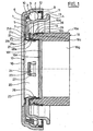
- the clutch abutment is completed by an operating element 16, visible in Figure 2.
- the operating element 16 may be a separate part of the control member actuating the device or be an integral part thereof.
- the operating element 16 may be constituted, for example, by the hydraulic piston of a hydraulically-controlled release stop device.
- the clutch abutment also comprises an axial securing means 17 between the operating element 16 and the thrust bearing, more specifically the non-rotating ring 1.
- the axial securing means 17 is of the type allowing a certain radial displacement of the ring non-rotating 1 of the thrust bearing relative to the operating element 16.
- the operating element 16 is in the form of a tube portion made of synthetic material provided with a cylindrical bore and an outer surface 16a also cylindrical and surrounded at a distance by the spring.
- the end of the operating element 16, on the side of the axial securing means 17, has a slightly reduced outside diameter with a shoulder 16b and an annular groove 16c.
- the annular groove 16c open to the outside may have a substantially radial flange opposite the shoulder 16b.
- a radial surface 16d forms the front end of the operating element 16 on the side of the axial fastening means 17.
- the bore of the operating element 16 is stepped and comprises a large diameter portion 16e on the side of the operating means.
- the axial securing means 17 comprises a fixing ring 18 and an additional ring 19, separate from each other.
- the fixing ring 18 is in the form of a one-piece piece made of sheet metal, of generally L-shaped annular shape.
- the fixing ring 18 comprises an axial annular portion 20, and an axially elastic portion 21.
- the axial portion 20 is disposed in the bore of the radial portion 5 of the non-rotating ring 1 and in contact with the large diameter portion 16e of the bore of the element the axial portion 20 projects beyond the radial portion 5 and is extended by the elastic portion 21.
- the difference in diameter between the axial portion 20 and the bore of the radial portion 5 allows a certain radial displacement of the thrust bearing relative to the actuating element 16 and thus allows the bearing to be self-aligned relative to the diaphragm of the clutch.
- the axial portion 20 are formed by cutting a plurality of U-shaped windows 22, leaving tabs 23 having a certain radial elasticity, attached to the axial portion 20 of the side of its free end, close to the shoulder 16f.
- the tongues 23 comprise a free end 24 slightly bent obliquely outwards. The free ends of the tongues 23 are directed towards the front part of the abutment.
- the term frontal portion of the stop the portion intended to come into contact with the diaphragm.
- the elastic portion 21 extends outwardly from the axial portion 20 and has a maximum diameter greater than the bore of the radial portion 5 to interfere with said radial portion 5.
- the elastic portion 21 has a generally radial shape, slightly inclined towards the radial portion 5, with a concave zone 21a on the side of the radial portion 5 near the axial portion 20, then a frustoconical zone 21b, then a convex zone 21c adapted to come into contact on the radial portion 5 with relative radial sliding due to self-alignment, and an outer rim 21d moved away from the radial portion 5.
- a plurality of windows 25 are formed in the elastic portion 21 substantially at the frustoconical zone. The windows 25 make it possible to increase the axial flexibility of the elastic portion 21.
- the elastic portion may be cut into a plurality of tongues coming into contact with the radial portion 5.
- the tongues may be from an inner edge and directed outwards or from an outer edge and directed towards the outside. inside.
- the additional fixing ring 19 is in the form of a one-piece piece made of stamped sheet metal, of generally L-shaped annular shape.
- the additional ring 19 comprises an annular axial portion 26, and an annular radial portion 27 extending inwards from the axial portion 26 protruding beyond the large diameter portion 16e of the bore of the operating member 16.
- the radial portion 27 serves as a stop surface at the free ends 24 of the tongues 23 for the axial retention of the fixing ring 18.
- the radial portion 27 is in contact on one side with the radial end face of the operating element 16 and the free ends 24 of the tongues 23, and the other side with the radial portion 5 of the non-rotating ring 1.
- the axial portion 26 is mounted around the free end of reduced diameter of the operating element 16.
- the free end of the axial portion 26 is located at a short distance from the shoulder 16b.
- In the axial portion 26, are formed a plurality of U-shaped cuts, leaving as many tongues 28 whose free end is directed axially towards the radial portion 27 and radially inwardly.
- the cutouts leave the axial portion 26, a continuous annular portion, remote from the radial portion 27, and a portion in which the tongues 28 are formed.
- the fixing ring 18 and the operating element 16 may have substantially identical inner diameters.
- the tongues 28 project into the annular groove 16c with their free ends 28a abutting against the surface radial of said annular groove 16c on the opposite side to the shoulder 16b.
- the additional ring 19 and the operating element 16 may have substantially identical external diameters, in order to avoid unevenness likely to affect the ease of assembly.
- the additional ring 19 and the operating element 16 can be fixed to one another by a simple axial movement.
- the free ends 28a of the tongues 28 are able to fade outward before entering the annular groove 16c by taking up at least part of their original position in the free state, thus ensuring the joining of the additional ring 19 and the operating element 16, surely.
- the assembly can be carried out as follows.
- the actuating element 16 is brought into the additional ring 19 by axial movement, the axial portion 26 surrounding the free end of reduced diameter of the operating element 16.
- the tabs 28 fade outwards in order to cross the flange of the groove 16c, and then fold inwards by elasticity in the groove 16c snapping.
- the non-rotating ring 1 is then moved axially, the radial portion 5 coming into contact with the radial portion 27 of the additional ring 19.
- the axial portion 26 is then substantially at the axial level of the rolling elements 3.
- the fixing ring 18 is then moved by an axial movement on the opposite side of the radial portion 5 of the non-rotating ring 1.
- the axial portion 20 passes into the bore of the radial portion 5 of the non-rotating ring 1, in the free end of the radial portion 27 of the additional ring 19 and in the large-diameter portion 16e of the operating element 16.
- the tongues 23 fade inwards crossing the free end of the radial portion 27 of the ring 19.
- the elastic portion 21 comes into contact with the radial portion 5 of the non-rotating ring 1.
- the tongues 23 by elasticity then deviate outwards in contact with the bore of the large diameter portion 16e of the operating element 16 after the free ends 24 of the tongues 23 have crossed the free end of the radial portion 27.
- the free ends 24 of the tongues 23 then come into abutting contact with the radial portion 27 thus preventing a separation of the fixing ring 18, the subassembly formed by the additional ring 19, the non-rotating ring 1 and the operating element 16.
- the non-rotating ring 1 is held axially with a slight prestress between the elastic portion 21 on one side and the radial portion of the additional ring 19 on the other side, while retaining a radial clearance due to the difference in diameter between the axial portion 20 of the fixing ring 18 and the bore of the radial portion 5.
- this type of assembly is particularly simple, with a first axial movement to arrange the additional ring 19 on the operating element 16 and a second axial movement to position the fixing ring 18. It is freed from any step of folding a flange when assembling these elements.
- a ring-shaped sealing member 29 comprising a first axial portion 29a disposed in contact with the bore of the radial portion 5 of the non-rotating ring 1.
- the first axial portion 29a can be fitted or simply centered in said bore.
- the sealing member 29 is completed by a radial portion 29b in contact, on one side, with the radial portion 5 and, on the opposite side, with the outer edge of the elastic portion 21 of the fixing ring 18, and a second axial portion 29c facing away from the radial portion 5 and forming a narrow passage with the free end of the radial portion 7 of the rotating ring 6 to improve the sealing of the bearing.
- the fixing ring 18 is in contact with an element mounted on the non-rotating ring 1, this element ensuring the seal between the rotating and non-rotating rings.
- the additional ring is removed.
- the radial portion 5 of the non-rotating ring 1 is in direct contact with the radial end surface of the operating element 16.
- the operating element 16 is provided with an annular rib 16b projecting inwards, adjacent to the radial end surface, and limiting the large diameter portion 16e.
- the rib 16h serves as a stop at the free ends 24 of the tongues 23.
- a sealing member 29 is provided. However, one could consider a device according to Figure 6 without sealing member 29 as that of Figure 1.
- the outer surface 16a of the actuating element 16 is cylindrical.
- the invention achieves a fastening system of the thrust bearing and self-centering very compact and easy to assemble, even automatically. Simple axial movements are sufficient for mounting which is therefore economical and reliable.
- the operating element is simple in shape and therefore robust.
Landscapes
- Engineering & Computer Science (AREA)
- General Engineering & Computer Science (AREA)
- Mechanical Engineering (AREA)
- Mechanical Operated Clutches (AREA)
Claims (21)
- Kupplungsausrücklagervorrichtung, zu der gehören: ein Ausrückelement (16), ein Wälzlager, das mit einem stillstehenden Ring (1) und einem umlaufenden Ring (6) versehen ist, wobei das Wälzlager in axialer Richtung mit dem Ausrückelement (16) starr verbunden ist, und ein ringförmiger Befestigungsring (18), der mit einem in dem Ausrückelement befestigten Abschnitt und mit einem in axialer Richtung elastischen Abschnitt (21) ausgebildet ist, wobei der Befestigungsring (18) dazu dient, den stillstehenden Ring an dem Ausrückelement (16) in axialer Richtung zu sichern, wobei eine radiale Versetzung ermöglicht ist, dadurch gekennzeichnet, dass der in dem Ausrückelement befestigte Abschnitt ein ringförmiger axialer Abschnitt ist und in einem zylindrischen Innenraum des Ausrückelements (16) angebracht ist, und dass der axial elastische Abschnitt an dem stillstehenden Ring (1) an jener Seite anliegt, die von dem Betätigungselement (16) abliegt.
- Vorrichtung nach Anspruch 1, dadurch gekennzeichnet, dass der Befestigungsring (18) mit dem Ausrückelement in unmittelbarer Berührung steht.
- Vorrichtung nach einem der vorhergehenden Ansprüche, dadurch gekennzeichnet, dass der elastische Abschnitt (21) im Wesentlichen radial ist und gegen den radialen Abschnitt (5) des stillstehenden Rings (1) geneigt ist.
- Vorrichtung nach einem der vorhergehenden Ansprüche, dadurch gekennzeichnet, dass der elastische Abschnitt (21) auf der Seite des stillstehenden Rings eine konvexe Fläche aufweist.
- Vorrichtung nach einem der vorhergehenden Ansprüche, dadurch gekennzeichnet, dass in dem elastischen Abschnitt (21) eine Anzahl von Öffnungen (25) ausgebildet sind.
- Vorrichtung nach einem der vorhergehenden Ansprüche, dadurch gekennzeichnet, dass der elastische Abschnitt (21) eine Anzahl von in axialer Richtung elastischen Zungen enthält.
- Vorrichtung nach einem der vorhergehenden Ansprüche, dadurch gekennzeichnet, dass der Befestigungsring (18) einstückig hergestellt ist.
- Vorrichtung nach einem der vorhergehenden Ansprüche, dadurch gekennzeichnet, dass der axiale Abschnitt des Befestigungsrings (18) Befestigungszungen (23) zur Befestigung an dem Ausrückelement aufweist.
- Vorrichtung nach Anspruch 8, dadurch gekennzeichnet, dass das freie Ende (24) der Befestigungszungen (23) mit einer starr mit dem Ausrückelement verbundenen Fläche in Berührung steht.
- Vorrichtung nach Anspruch 9, dadurch gekennzeichnet, dass das freie Ende (24) der Befestigungszungen mit einer im Wesentlichen radial sich erstreckenden Fläche des Ausrückelements in Berührung steht.
- Vorrichtung nach einem der vorhergehenden Ansprüche, dadurch gekennzeichnet, dass zu der Vorrichtung ein starr mit dem Ausrückelement verbundener zusätzlicher Befestigungsring (19) gehört.
- Vorrichtung nach Anspruch 11, dadurch gekennzeichnet, dass der zusätzliche Befestigungsring (19) einen axialen Abschnitt (26) und einen mit dem Ausrückelement in Berührung stehenden radialen Abschnitt (27) aufweist.
- Vorrichtung nach Anspruch 12, dadurch gekennzeichnet, dass der radiale Abschnitt (27) des zusätzlichen Befestigungsrings (19) mit dem stillstehenden Ring (1) in Berührung steht.
- Vorrichtung nach Anspruch 12 oder 13, dadurch gekennzeichnet, dass der zusätzliche Befestigungsring (19) Befestigungszungen (28) zur Befestigung an dem Ausrückelement aufweist, wobei die Zungen mit dem axialen Abschnitt (26) einstückig ausgebildet sind.
- Vorrichtung nach einem der Ansprüche 12 bis 13, dadurch gekennzeichnet, dass der axiale Abschnitt (26) des zusätzlichen Befestigungsrings (19) einen Abschnitt des Ausrückelements umgibt.
- Vorrichtung nach einem der Ansprüche 11 bis 15, dadurch gekennzeichnet, dass der zusätzliche Befestigungsring (19) eine Haltefläche hinsichtlich des Befestigungsrings (18) enthält.
- Vorrichtung nach einem der vorhergehenden Ansprüche, dadurch gekennzeichnet, dass der stillstehende Ring (1) einen nach innen gerichteten radial sich erstreckenden Abschnitt (4) aufweist, der in axialer Richtung zwischen dem elastischen Abschnitt (21) des Befestigungsrings (18) und einer starr mit dem Ausrückelement verbundenen Fläche (16) angeordnet ist.
- Vorrichtung nach einem der vorhergehenden Ansprüche, dadurch gekennzeichnet, dass der stillstehende Ring (1) unmittelbar mit dem elastischen Abschnitt (21) des Befestigungsrings (18) in Berührung steht.
- Vorrichtung nach einem der Ansprüche 1 bis 18, dadurch gekennzeichnet, dass zu der Vorrichtung ein Dichtungselement (29) gehört, das starr mit dem stillstehenden Ring verbunden ist und mit dem elastischen Abschnitt (21) des Befestigungsrings (18) in Berührung steht.
- Vorrichtung nach einem der vorhergehenden Ansprüche, dadurch gekennzeichnet, dass das Ausrückelement (16) ein hydraulischer Stößel ist.
- Kupplungsbetätigungssystem, das eine Vorrichtung nach einem der vorhergehenden Ansprüche enthält.
Applications Claiming Priority (2)
| Application Number | Priority Date | Filing Date | Title |
|---|---|---|---|
| FR0307356 | 2003-06-18 | ||
| FR0307356A FR2856448B1 (fr) | 2003-06-18 | 2003-06-18 | Butee de debrayage |
Publications (2)
| Publication Number | Publication Date |
|---|---|
| EP1489325A1 EP1489325A1 (de) | 2004-12-22 |
| EP1489325B1 true EP1489325B1 (de) | 2006-07-19 |
Family
ID=33396799
Family Applications (1)
| Application Number | Title | Priority Date | Filing Date |
|---|---|---|---|
| EP04290822A Expired - Lifetime EP1489325B1 (de) | 2003-06-18 | 2004-03-29 | Ausrücksvorrichtung |
Country Status (4)
| Country | Link |
|---|---|
| US (1) | US7222709B2 (de) |
| EP (1) | EP1489325B1 (de) |
| DE (1) | DE602004001550T2 (de) |
| FR (1) | FR2856448B1 (de) |
Families Citing this family (26)
| Publication number | Priority date | Publication date | Assignee | Title |
|---|---|---|---|---|
| FR2829429B1 (fr) * | 2001-09-12 | 2003-12-12 | Skf Ab | Dispositif de butee de suspension |
| FR2832201B1 (fr) * | 2001-11-13 | 2004-03-19 | Skf Ab | Dispositif tendeur instrumente et procede de controle associe |
| FR2835297B1 (fr) | 2002-01-29 | 2004-04-16 | Skf Ab | Support de fixation, palier a roulement et procede de montage associes |
| FR2841304B1 (fr) | 2002-06-20 | 2007-01-05 | Skf Ab | Dispositif de tension pour mise en precontrainte d'une tige et procede de tension associe |
| FR2841990B1 (fr) | 2002-07-02 | 2005-07-29 | Skf Ab | Dispositif de palier a roulement instrumente et moteur electrique ainsi equipe |
| FR2851624B1 (fr) | 2003-02-26 | 2006-03-31 | Skf Ab | Palier a roulement instrumente |
| FR2853065B1 (fr) * | 2003-03-27 | 2006-01-06 | Skf Ab | Instrument de mesure portatif, notamment pur la pratique sportive. |
| FR2853165B1 (fr) * | 2003-03-27 | 2005-12-02 | Skf Ab | Ensemble capteur, et boitier pour la realisation d'un tel ensemble. |
| FR2856757B1 (fr) * | 2003-06-27 | 2006-10-20 | Skf Ab | Palier a roulement instrumente et codeur pour ensemble capteur d'informations |
| FR2858376B1 (fr) * | 2003-07-28 | 2006-03-03 | Skf France | Dispositif de palier a roue libre avec limitateur de couple. |
| FR2861459B1 (fr) * | 2003-10-22 | 2006-02-24 | Skf Ab | Systeme de mesure de rotation haute resolution absolu multitour et roulement equipe d'un tel systeme. |
| FR2872558B1 (fr) * | 2004-07-02 | 2006-09-29 | Skf Ab | Butee de debrayage et procede de fabrication |
| FR2882580B1 (fr) * | 2005-02-28 | 2007-05-25 | Skf Ab | Dispositif de galet tendeur de courroie instrumente et procede de controle associe |
| DE102005053612A1 (de) * | 2005-11-10 | 2007-05-16 | Schaeffler Kg | Ausrücklager für eine Betätigungseinrichtung einer Schaltkupplung |
| FR2902699B1 (fr) | 2006-06-26 | 2010-10-22 | Skf Ab | Dispositif de butee de suspension et jambe de force. |
| FR2906587B1 (fr) | 2006-10-03 | 2009-07-10 | Skf Ab | Dispositif de galet tendeur. |
| FR2908852B1 (fr) * | 2006-11-22 | 2012-07-13 | Roulements Soc Nouvelle | Butee de suspension a couple maitrise et jambe de suspension de roue directrice de vehicule. |
| FR2913081B1 (fr) | 2007-02-27 | 2009-05-15 | Skf Ab | Dispositif de poulie debrayable |
| FR2936032B1 (fr) * | 2008-09-16 | 2011-08-26 | Skf Ab | Roulement, son utilisation et vehicule automobile equipe d'un tel roulement. |
| DE102012200619A1 (de) * | 2012-01-17 | 2013-07-18 | Schaeffler Technologies AG & Co. KG | Wälzlageranordnung, insbesondere Aurücklageranordnung |
| US9308636B2 (en) | 2012-02-03 | 2016-04-12 | Milwaukee Electric Tool Corporation | Rotary hammer with vibration dampening |
| DE102012206449B4 (de) | 2012-04-19 | 2019-10-17 | Schaeffler Technologies AG & Co. KG | Planetengetriebe mit integriertem Lagerinnenring |
| CN104169613B (zh) | 2012-04-19 | 2017-11-28 | 舍弗勒技术股份两合公司 | 具有差速器的行星齿轮传动机构 |
| DE102016204500B3 (de) * | 2016-03-18 | 2017-08-03 | Schaeffler Technologies AG & Co. KG | Ausrücklager |
| DE102016207088A1 (de) * | 2016-04-26 | 2017-10-26 | Schaeffler Technologies AG & Co. KG | Nehmerzylinder für eine Kupplungsbetätigungseinheit |
| KR102132347B1 (ko) * | 2019-01-29 | 2020-07-09 | 셰플러코리아(유) | 클러치 릴리즈 베어링 |
Family Cites Families (15)
| Publication number | Priority date | Publication date | Assignee | Title |
|---|---|---|---|---|
| FR2384990A1 (fr) | 1977-03-25 | 1978-10-20 | Skf Cie Applic Mecanique | Butee d'embrayage a auto-alignement elastique comportant des moyens de guidage |
| FR2461158A1 (fr) | 1979-07-10 | 1981-01-30 | Skf Cie Applic Mecanique | Butee d'embrayage a auto-centrage |
| FR2577291B1 (fr) * | 1985-02-08 | 1989-10-13 | Valeo | Butee d'embrayage autocentreuse, notamment pour vehicule automobile, a assemblage compact simplifie |
| FR2611244B1 (fr) * | 1987-02-20 | 1991-07-05 | Valeo | Butee de debrayage a piece elastique a action axiale, notamment pour vehicule automobile |
| JPS63246516A (ja) * | 1987-04-02 | 1988-10-13 | Nippon Seiko Kk | クラツチレリ−ズ軸受装置 |
| FR2645929B1 (fr) * | 1989-04-18 | 1991-06-07 | Roulements Soc Nouvelle | Dispositif de serrage d'un roulement de butee sur un support coulissant |
| JPH06213251A (ja) | 1993-01-20 | 1994-08-02 | Koyo Seiko Co Ltd | 自動調心型クラッチレリーズ軸受装置 |
| FR2730534B1 (fr) * | 1995-02-09 | 1997-04-04 | Valeo | Butee de debrayage a commande hydraulique pour un embrayage a diaphragme de vehicule automobile |
| US6415900B1 (en) * | 1996-12-23 | 2002-07-09 | Valeo | Hydraulic control receiver with closing plate |
| DE19716218C2 (de) * | 1997-04-18 | 2001-08-30 | Schaeffler Waelzlager Ohg | Kupplungsausrücklager |
| FR2772444B1 (fr) | 1997-12-11 | 2000-06-16 | Valeo | Recepteur hydraulique pour commande d'embrayage, notamment pour vehicule automobile |
| FR2807802B1 (fr) * | 2000-04-12 | 2002-07-26 | Skf France | Butee de debrayage et element d'attaque pour butee de debrayage |
| KR20020084145A (ko) | 2000-12-22 | 2002-11-04 | 발레오 | 자동차용 클러치의 스러스트 베어링 및 피스톤과 볼베어링의 조립 방법 |
| FR2819864B1 (fr) | 2001-01-23 | 2003-04-25 | Skf Ab | Dispositif de butee de debrayage autocentreuse |
| DE10148388A1 (de) | 2001-09-29 | 2003-04-24 | Ina Schaeffler Kg | Abdichtung für ein Wälzlager |
-
2003
- 2003-06-18 FR FR0307356A patent/FR2856448B1/fr not_active Expired - Fee Related
-
2004
- 2004-03-29 EP EP04290822A patent/EP1489325B1/de not_active Expired - Lifetime
- 2004-03-29 DE DE602004001550T patent/DE602004001550T2/de not_active Expired - Lifetime
- 2004-06-17 US US10/870,483 patent/US7222709B2/en not_active Expired - Fee Related
Also Published As
| Publication number | Publication date |
|---|---|
| US20050011717A1 (en) | 2005-01-20 |
| DE602004001550D1 (de) | 2006-08-31 |
| FR2856448A1 (fr) | 2004-12-24 |
| FR2856448B1 (fr) | 2006-09-01 |
| US7222709B2 (en) | 2007-05-29 |
| DE602004001550T2 (de) | 2007-07-05 |
| EP1489325A1 (de) | 2004-12-22 |
Similar Documents
| Publication | Publication Date | Title |
|---|---|---|
| EP1489325B1 (de) | Ausrücksvorrichtung | |
| EP1489327B1 (de) | Ausrücksvorrichtung und Montageverfahren | |
| EP1225360B1 (de) | Selbstzentrierende Vorrichtung für ein Kupplungsausrücklager | |
| EP0941414B1 (de) | Wälzlager für kraftfahrzeuglenksäulen | |
| FR2860847A1 (fr) | Dispositif de butee de debrayage | |
| EP1146244B1 (de) | Kupplungsausrücklager | |
| FR2883347A1 (fr) | Butee de debrayage | |
| FR2619880A1 (fr) | Butee de debrayage, notamment pour vehicules automobiles | |
| FR2898951A1 (fr) | Butee de debrayage auto-centreuse | |
| EP1988002B1 (de) | Wälzlagervorrichtung für Lenksäule | |
| FR2961280A1 (fr) | Dispositif de butee de debrayage comprenant une bague d'usure. | |
| EP0806581B1 (de) | Kupplungsausrücklager mit einem elastischen Ring | |
| FR2971825A1 (fr) | Palier a roulement, notamment pour dispositif de butee de debrayage. | |
| FR2928983A1 (fr) | Dispositif de butee de debrayage autocentreuse. | |
| EP0770789B1 (de) | Hydraulische Kupplungsbetätigungsvorrichtung | |
| FR2459906A1 (fr) | Butee d'embrayage a auto-centrage | |
| FR2760057A1 (fr) | Dispositif de roue libre a flasque de retenue et procede de mise en place du flasque | |
| FR2856122A1 (fr) | Butee de debrayage comportant des moyens de solidarisation avec l'organe de commande. | |
| FR2872235A1 (fr) | Butee de debrayage et procede de montage | |
| FR2876170A1 (fr) | Butee de debrayage autocentreuse et procede de montage | |
| EP0965004B1 (de) | Kupplungsausrücklager | |
| FR2652623A1 (fr) | Dispositif de butee d'embrayage a autocentrage du type tiree. | |
| FR2693523A1 (fr) | Butée de débrayage du type tirée. | |
| FR2911939A1 (fr) | Dispositif de butee de debrayage | |
| EP0926375B1 (de) | Kupplungsausrücklager mit seitlichen Halte- und Fürungsclips |
Legal Events
| Date | Code | Title | Description |
|---|---|---|---|
| PUAI | Public reference made under article 153(3) epc to a published international application that has entered the european phase |
Free format text: ORIGINAL CODE: 0009012 |
|
| AK | Designated contracting states |
Kind code of ref document: A1 Designated state(s): AT BE BG CH CY CZ DE DK EE ES FI FR GB GR HU IE IT LI LU MC NL PL PT RO SE SI SK TR |
|
| AX | Request for extension of the european patent |
Extension state: AL HR LT LV MK |
|
| 17P | Request for examination filed |
Effective date: 20050114 |
|
| 17Q | First examination report despatched |
Effective date: 20050330 |
|
| AKX | Designation fees paid |
Designated state(s): DE FR GB IT |
|
| GRAP | Despatch of communication of intention to grant a patent |
Free format text: ORIGINAL CODE: EPIDOSNIGR1 |
|
| GRAS | Grant fee paid |
Free format text: ORIGINAL CODE: EPIDOSNIGR3 |
|
| GRAA | (expected) grant |
Free format text: ORIGINAL CODE: 0009210 |
|
| AK | Designated contracting states |
Kind code of ref document: B1 Designated state(s): DE FR GB IT |
|
| PG25 | Lapsed in a contracting state [announced via postgrant information from national office to epo] |
Ref country code: IT Free format text: LAPSE BECAUSE OF FAILURE TO SUBMIT A TRANSLATION OF THE DESCRIPTION OR TO PAY THE FEE WITHIN THE PRESCRIBED TIME-LIMIT;WARNING: LAPSES OF ITALIAN PATENTS WITH EFFECTIVE DATE BEFORE 2007 MAY HAVE OCCURRED AT ANY TIME BEFORE 2007. THE CORRECT EFFECTIVE DATE MAY BE DIFFERENT FROM THE ONE RECORDED. Effective date: 20060719 Ref country code: GB Free format text: LAPSE BECAUSE OF FAILURE TO SUBMIT A TRANSLATION OF THE DESCRIPTION OR TO PAY THE FEE WITHIN THE PRESCRIBED TIME-LIMIT Effective date: 20060719 |
|
| REG | Reference to a national code |
Ref country code: GB Ref legal event code: FG4D Free format text: NOT ENGLISH |
|
| REF | Corresponds to: |
Ref document number: 602004001550 Country of ref document: DE Date of ref document: 20060831 Kind code of ref document: P |
|
| GBV | Gb: ep patent (uk) treated as always having been void in accordance with gb section 77(7)/1977 [no translation filed] |
Effective date: 20060719 |
|
| PLBE | No opposition filed within time limit |
Free format text: ORIGINAL CODE: 0009261 |
|
| STAA | Information on the status of an ep patent application or granted ep patent |
Free format text: STATUS: NO OPPOSITION FILED WITHIN TIME LIMIT |
|
| 26N | No opposition filed |
Effective date: 20070420 |
|
| PGFP | Annual fee paid to national office [announced via postgrant information from national office to epo] |
Ref country code: FR Payment date: 20120406 Year of fee payment: 9 |
|
| PGFP | Annual fee paid to national office [announced via postgrant information from national office to epo] |
Ref country code: IT Payment date: 20120326 Year of fee payment: 9 |
|
| REG | Reference to a national code |
Ref country code: FR Ref legal event code: ST Effective date: 20131129 |
|
| PG25 | Lapsed in a contracting state [announced via postgrant information from national office to epo] |
Ref country code: FR Free format text: LAPSE BECAUSE OF NON-PAYMENT OF DUE FEES Effective date: 20130402 |
|
| PG25 | Lapsed in a contracting state [announced via postgrant information from national office to epo] |
Ref country code: IT Free format text: LAPSE BECAUSE OF NON-PAYMENT OF DUE FEES Effective date: 20130329 |
|
| PGFP | Annual fee paid to national office [announced via postgrant information from national office to epo] |
Ref country code: DE Payment date: 20150601 Year of fee payment: 12 |
|
| REG | Reference to a national code |
Ref country code: DE Ref legal event code: R119 Ref document number: 602004001550 Country of ref document: DE |
|
| PG25 | Lapsed in a contracting state [announced via postgrant information from national office to epo] |
Ref country code: DE Free format text: LAPSE BECAUSE OF NON-PAYMENT OF DUE FEES Effective date: 20161001 |