EP1489325B1 - Clutch release device - Google Patents
Clutch release device Download PDFInfo
- Publication number
- EP1489325B1 EP1489325B1 EP04290822A EP04290822A EP1489325B1 EP 1489325 B1 EP1489325 B1 EP 1489325B1 EP 04290822 A EP04290822 A EP 04290822A EP 04290822 A EP04290822 A EP 04290822A EP 1489325 B1 EP1489325 B1 EP 1489325B1
- Authority
- EP
- European Patent Office
- Prior art keywords
- operating element
- fixing ring
- radial
- ring
- axial
- Prior art date
- Legal status (The legal status is an assumption and is not a legal conclusion. Google has not performed a legal analysis and makes no representation as to the accuracy of the status listed.)
- Expired - Lifetime
Links
- 238000005096 rolling process Methods 0.000 claims description 13
- 238000007789 sealing Methods 0.000 claims description 9
- 210000002105 tongue Anatomy 0.000 description 22
- 238000006073 displacement reaction Methods 0.000 description 4
- 230000014759 maintenance of location Effects 0.000 description 2
- 239000002184 metal Substances 0.000 description 2
- 238000013270 controlled release Methods 0.000 description 1
- 238000005520 cutting process Methods 0.000 description 1
- 230000001627 detrimental effect Effects 0.000 description 1
- 230000000694 effects Effects 0.000 description 1
- 238000005304 joining Methods 0.000 description 1
- 238000004519 manufacturing process Methods 0.000 description 1
- 238000000034 method Methods 0.000 description 1
- 238000000926 separation method Methods 0.000 description 1
- 229920002994 synthetic fiber Polymers 0.000 description 1
Images


Classifications
-
- F—MECHANICAL ENGINEERING; LIGHTING; HEATING; WEAPONS; BLASTING
- F16—ENGINEERING ELEMENTS AND UNITS; GENERAL MEASURES FOR PRODUCING AND MAINTAINING EFFECTIVE FUNCTIONING OF MACHINES OR INSTALLATIONS; THERMAL INSULATION IN GENERAL
- F16D—COUPLINGS FOR TRANSMITTING ROTATION; CLUTCHES; BRAKES
- F16D23/00—Details of mechanically-actuated clutches not specific for one distinct type
- F16D23/12—Mechanical clutch-actuating mechanisms arranged outside the clutch as such
- F16D23/14—Clutch-actuating sleeves or bearings; Actuating members directly connected to clutch-actuating sleeves or bearings
-
- F—MECHANICAL ENGINEERING; LIGHTING; HEATING; WEAPONS; BLASTING
- F16—ENGINEERING ELEMENTS AND UNITS; GENERAL MEASURES FOR PRODUCING AND MAINTAINING EFFECTIVE FUNCTIONING OF MACHINES OR INSTALLATIONS; THERMAL INSULATION IN GENERAL
- F16C—SHAFTS; FLEXIBLE SHAFTS; ELEMENTS OR CRANKSHAFT MECHANISMS; ROTARY BODIES OTHER THAN GEARING ELEMENTS; BEARINGS
- F16C19/00—Bearings with rolling contact, for exclusively rotary movement
- F16C19/02—Bearings with rolling contact, for exclusively rotary movement with bearing balls essentially of the same size in one or more circular rows
- F16C19/14—Bearings with rolling contact, for exclusively rotary movement with bearing balls essentially of the same size in one or more circular rows for both radial and axial load
- F16C19/16—Bearings with rolling contact, for exclusively rotary movement with bearing balls essentially of the same size in one or more circular rows for both radial and axial load with a single row of balls
- F16C19/163—Bearings with rolling contact, for exclusively rotary movement with bearing balls essentially of the same size in one or more circular rows for both radial and axial load with a single row of balls with angular contact
-
- F—MECHANICAL ENGINEERING; LIGHTING; HEATING; WEAPONS; BLASTING
- F16—ENGINEERING ELEMENTS AND UNITS; GENERAL MEASURES FOR PRODUCING AND MAINTAINING EFFECTIVE FUNCTIONING OF MACHINES OR INSTALLATIONS; THERMAL INSULATION IN GENERAL
- F16C—SHAFTS; FLEXIBLE SHAFTS; ELEMENTS OR CRANKSHAFT MECHANISMS; ROTARY BODIES OTHER THAN GEARING ELEMENTS; BEARINGS
- F16C2361/00—Apparatus or articles in engineering in general
- F16C2361/43—Clutches, e.g. disengaging bearing
-
- F—MECHANICAL ENGINEERING; LIGHTING; HEATING; WEAPONS; BLASTING
- F16—ENGINEERING ELEMENTS AND UNITS; GENERAL MEASURES FOR PRODUCING AND MAINTAINING EFFECTIVE FUNCTIONING OF MACHINES OR INSTALLATIONS; THERMAL INSULATION IN GENERAL
- F16D—COUPLINGS FOR TRANSMITTING ROTATION; CLUTCHES; BRAKES
- F16D25/00—Fluid-actuated clutches
- F16D25/08—Fluid-actuated clutches with fluid-actuated member not rotating with a clutching member
- F16D25/082—Fluid-actuated clutches with fluid-actuated member not rotating with a clutching member the line of action of the fluid-actuated members co-inciding with the axis of rotation
- F16D25/083—Actuators therefor
Definitions
- the present invention relates to the field of clutch release stops intended to act on the diaphragm of a clutch, in particular for a motor vehicle.
- the invention is applicable to clutch release bearings comprising a bearing of which one of the rings is rotating and the other ring is fixed.
- the rotating ring Between the rotating ring and the fixed ring are arranged balls regularly distributed in the circumferential direction by means of a cage, the rotating ring being provided with a substantially radial engagement surface intended to come into contact with the fingertips. composing the diaphragm of the clutch.
- An operating element supports the bearing and, under the action of a control member (mechanical, electrical or hydraulic), axially moves the thrust bearing against the diaphragm of the clutch.
- the document WO 02/052163 describes a clutch for a motor vehicle clutch equipped with an axially movable piston and a ring hooked on the piston by means of resilient gripping means having an axial effect.
- One face of the ring bears on an attachment face formed in the piston.
- the clamping means bear on the opposite face of the ring and another attachment face also formed in the piston.
- the resilient clamping means is in the form of an annular fastener provided with lugs projecting in axial bores in the piston which open into radial bores.
- the shape of the piston is therefore relatively complex, which is detrimental in terms of cost.
- the piston, the fastener, the associated spring washer and the ring must be mounted simultaneously, which complicates the assembly process.
- the document FR-A-2 611 244 discloses a clutch release bearing provided with an elastic piece for fixing the non-rotating outer ring and the operating element.
- This part consists of a radial ring from which two diametrically opposed tabs are formed inwardly projecting, comprising a substantially oblique radial portion followed by an essentially axial and also oblique portion, facing away from the rolling elements and towards the outside. outside and ending with an inward folded rim, thus having an overall shape of S. There is no axial portion.
- the tabs are mounted in an opening through a flange of an operating element also provided with an axially elongated sleeve.
- the present invention proposes to remedy these disadvantages.
- the present invention provides a particularly robust and reliable disengagement abutment with elements of relatively simple shape.
- the clutch abutment device is of the type comprising an operating element, and a rolling bearing provided with a non-rotating ring and a rotating race, said rolling bearing being axially secured. of the operating element.
- the device comprises an annular fixing ring provided with an axial annular portion mounted in the operating element and an axially elastic portion axially bearing on the non-rotating ring on the side axially opposite to the operating element, said ring annular being able to maintain the non-rotating ring axially integral with the actuating element while allowing a radial displacement.
- the axial portion of the fixing ring is mounted in a bore of the operating element. This avoids an increase in congestion.
- Such a device is capable of acting on a diaphragm of clutch mechanism.
- the mounting of the stop is easy and convenient.
- the elastic fixing ring can be mounted after the assembly of the bearing, coming to engage with an axial movement.
- the operating element has a simple shape and is therefore robust.
- said fixing ring is in one piece.
- the fixing ring is therefore robust and economical.
- the fixing ring is in direct contact with the operating element.
- the elastic portion is substantially radial and is inclined towards the radial portion of the non-rotating ring.
- the elastic portion may have a convex surface on the side of the non-rotating ring. The convex surface can rub on the non-rotating ring during axial displacements, without excessive wear.
- a plurality of holes are formed in the elastic portion. This increases the axial flexibility of the elastic portion.
- the elastic portion may comprise a plurality of axially elastic tongues.
- the axial portion of the fixing ring comprises fixing tabs on the operating element.
- the fixing ring can be fixed to the operating element by a simple axial movement, the fixing tongues having a certain radial elasticity.
- the free end of the fixing tongues is in contact with a surface integral with the operating element.
- the free end of the fastening tongues is in contact with a substantially radial surface of the operating element.
- Said substantially radial surface may be formed by an annular rib formed in the bore of the operating element.
- the fixing ring may consist of an axial portion mounted in the operating element and supporting resilient tongues, and an axially resilient portion for holding the non-rotating ring.
- the device comprises an additional fixing ring integral with the operating element.
- the additional fixing ring comprises an axial portion and a radial portion in contact with the operating element.
- the radial portion of the additional fixing ring is in contact with the non-rotating ring. This prevents contact between the operating element and the non-rotating ring.
- the additional fixing ring comprises fixing tabs on the operating element, said tabs being derived from said axial portion.
- the axial portion of the additional fixing ring surrounds a part of the operating element.
- the additional fixing ring comprises a retaining surface of the fixing ring.
- the additional fastening ring may consist of an annular cup with an L-shaped section, with an axial portion mounted around the actuating element and supporting resilient tongues, and a radial contacting portion with the non-locating ring. rotating and retaining ring fixing.
- the retention of the fixing ring can be carried out by contact of the free end of the tongues of the fixing ring with a surface of the radial portion near its small diameter end.
- the non-rotating ring comprises an inwardly directed radial portion disposed axially between the elastic portion of the fixing ring and an integral surface of the operating element.
- Said integral surface of the operating element may be a surface of the additional ring or a surface of the operating element itself.
- the non-rotating ring may have a slightly greater minimum diameter, for example a few tenths of millimeters or a few millimeters to the outside diameter of the second axial portion.
- the axial portion of the fixing ring can pass into the area of smaller diameter of the non-rotating ring.
- the non-rotating ring is in direct contact with the elastic portion of the fixing ring.
- the device comprises a sealing element integral with the non-rotating ring and in contact with the elastic portion of the fixing ring.
- the sealing member can form a narrow passage with the rotating ring.
- the operating element is a hydraulic pusher.
- the invention also proposes a clutch control system equipped with a clutch release device of the type comprising an operating element, a rolling bearing provided with a non-rotating ring and a rotating ring in contact with a clutch. diaphragm, said rolling bearing being axially integral with the operating element.
- the device comprises an annular fixing ring provided with an axial annular portion mounted in the element of maneuvering and an elastic portion axially bearing on the non-rotating ring on the axially opposite side of the operating element, said annular ring being able to hold the non-rotating ring axially integral with the operating element while allowing movement radial.
- the fixing ring is economical to manufacture, easy to implement by a simple axial movement and compact.
- the clutch abutment comprises a thin-walled non-rotating bearing ring 1 made by stamping a sheet or tube having a circular portion-shaped raceway 2 for a row of rolling elements, here balls 3, said path having an axial meridian section with concave arcuate profile.
- the inner ring 1 has a radial portion 4 directed outwards and a portion radially inwardly directed 5, said radial portions 4 and 5 being disposed on one side and the other of the rolling elements 3.
- the non-rotating ring 1 is an inner ring.
- the non-rotating ring 1 may be an outer ring.
- the rolling bearing is completed by an outer ring 6 having a radial portion 7 projecting towards the inside of the assembly and a cylindrical portion 8 on the side of the radial portion 4.
- the radial portion 7 is able to come into contact with the surface of a diaphragm or an equivalent element, not shown, for actuating a clutch, especially a motor vehicle.
- the outer ring 6 also comprises a thin wall which can be made by stamping a sheet or a tube.
- the outer ring 6 has a circular raceway 9 in the form of a toroidal portion, for the row of rolling elements 3, said path having a meridian axial section a concave arcuate circle profile.
- the rolling elements 3 are held by a cage 10 between the raceway 2 of the inner race 1 and the raceway 9 of the outer race 6.
- the ball bearing is completed by a sealing member 11 sealingly mounted in the cylindrical portion 8 of the outer ring 5 and comprising a frame 12 and a flexible part 13 which rubs on a cylindrical surface of the non-rotating ring 1.
- the clutch abutment is completed by an operating element 16, visible in Figure 2.
- the operating element 16 may be a separate part of the control member actuating the device or be an integral part thereof.
- the operating element 16 may be constituted, for example, by the hydraulic piston of a hydraulically-controlled release stop device.
- the clutch abutment also comprises an axial securing means 17 between the operating element 16 and the thrust bearing, more specifically the non-rotating ring 1.
- the axial securing means 17 is of the type allowing a certain radial displacement of the ring non-rotating 1 of the thrust bearing relative to the operating element 16.
- the operating element 16 is in the form of a tube portion made of synthetic material provided with a cylindrical bore and an outer surface 16a also cylindrical and surrounded at a distance by the spring.
- the end of the operating element 16, on the side of the axial securing means 17, has a slightly reduced outside diameter with a shoulder 16b and an annular groove 16c.
- the annular groove 16c open to the outside may have a substantially radial flange opposite the shoulder 16b.
- a radial surface 16d forms the front end of the operating element 16 on the side of the axial fastening means 17.
- the bore of the operating element 16 is stepped and comprises a large diameter portion 16e on the side of the operating means.
- the axial securing means 17 comprises a fixing ring 18 and an additional ring 19, separate from each other.
- the fixing ring 18 is in the form of a one-piece piece made of sheet metal, of generally L-shaped annular shape.
- the fixing ring 18 comprises an axial annular portion 20, and an axially elastic portion 21.
- the axial portion 20 is disposed in the bore of the radial portion 5 of the non-rotating ring 1 and in contact with the large diameter portion 16e of the bore of the element the axial portion 20 projects beyond the radial portion 5 and is extended by the elastic portion 21.
- the difference in diameter between the axial portion 20 and the bore of the radial portion 5 allows a certain radial displacement of the thrust bearing relative to the actuating element 16 and thus allows the bearing to be self-aligned relative to the diaphragm of the clutch.
- the axial portion 20 are formed by cutting a plurality of U-shaped windows 22, leaving tabs 23 having a certain radial elasticity, attached to the axial portion 20 of the side of its free end, close to the shoulder 16f.
- the tongues 23 comprise a free end 24 slightly bent obliquely outwards. The free ends of the tongues 23 are directed towards the front part of the abutment.
- the term frontal portion of the stop the portion intended to come into contact with the diaphragm.
- the elastic portion 21 extends outwardly from the axial portion 20 and has a maximum diameter greater than the bore of the radial portion 5 to interfere with said radial portion 5.
- the elastic portion 21 has a generally radial shape, slightly inclined towards the radial portion 5, with a concave zone 21a on the side of the radial portion 5 near the axial portion 20, then a frustoconical zone 21b, then a convex zone 21c adapted to come into contact on the radial portion 5 with relative radial sliding due to self-alignment, and an outer rim 21d moved away from the radial portion 5.
- a plurality of windows 25 are formed in the elastic portion 21 substantially at the frustoconical zone. The windows 25 make it possible to increase the axial flexibility of the elastic portion 21.
- the elastic portion may be cut into a plurality of tongues coming into contact with the radial portion 5.
- the tongues may be from an inner edge and directed outwards or from an outer edge and directed towards the outside. inside.
- the additional fixing ring 19 is in the form of a one-piece piece made of stamped sheet metal, of generally L-shaped annular shape.
- the additional ring 19 comprises an annular axial portion 26, and an annular radial portion 27 extending inwards from the axial portion 26 protruding beyond the large diameter portion 16e of the bore of the operating member 16.
- the radial portion 27 serves as a stop surface at the free ends 24 of the tongues 23 for the axial retention of the fixing ring 18.
- the radial portion 27 is in contact on one side with the radial end face of the operating element 16 and the free ends 24 of the tongues 23, and the other side with the radial portion 5 of the non-rotating ring 1.
- the axial portion 26 is mounted around the free end of reduced diameter of the operating element 16.
- the free end of the axial portion 26 is located at a short distance from the shoulder 16b.
- In the axial portion 26, are formed a plurality of U-shaped cuts, leaving as many tongues 28 whose free end is directed axially towards the radial portion 27 and radially inwardly.
- the cutouts leave the axial portion 26, a continuous annular portion, remote from the radial portion 27, and a portion in which the tongues 28 are formed.
- the fixing ring 18 and the operating element 16 may have substantially identical inner diameters.
- the tongues 28 project into the annular groove 16c with their free ends 28a abutting against the surface radial of said annular groove 16c on the opposite side to the shoulder 16b.
- the additional ring 19 and the operating element 16 may have substantially identical external diameters, in order to avoid unevenness likely to affect the ease of assembly.
- the additional ring 19 and the operating element 16 can be fixed to one another by a simple axial movement.
- the free ends 28a of the tongues 28 are able to fade outward before entering the annular groove 16c by taking up at least part of their original position in the free state, thus ensuring the joining of the additional ring 19 and the operating element 16, surely.
- the assembly can be carried out as follows.
- the actuating element 16 is brought into the additional ring 19 by axial movement, the axial portion 26 surrounding the free end of reduced diameter of the operating element 16.
- the tabs 28 fade outwards in order to cross the flange of the groove 16c, and then fold inwards by elasticity in the groove 16c snapping.
- the non-rotating ring 1 is then moved axially, the radial portion 5 coming into contact with the radial portion 27 of the additional ring 19.
- the axial portion 26 is then substantially at the axial level of the rolling elements 3.
- the fixing ring 18 is then moved by an axial movement on the opposite side of the radial portion 5 of the non-rotating ring 1.
- the axial portion 20 passes into the bore of the radial portion 5 of the non-rotating ring 1, in the free end of the radial portion 27 of the additional ring 19 and in the large-diameter portion 16e of the operating element 16.
- the tongues 23 fade inwards crossing the free end of the radial portion 27 of the ring 19.
- the elastic portion 21 comes into contact with the radial portion 5 of the non-rotating ring 1.
- the tongues 23 by elasticity then deviate outwards in contact with the bore of the large diameter portion 16e of the operating element 16 after the free ends 24 of the tongues 23 have crossed the free end of the radial portion 27.
- the free ends 24 of the tongues 23 then come into abutting contact with the radial portion 27 thus preventing a separation of the fixing ring 18, the subassembly formed by the additional ring 19, the non-rotating ring 1 and the operating element 16.
- the non-rotating ring 1 is held axially with a slight prestress between the elastic portion 21 on one side and the radial portion of the additional ring 19 on the other side, while retaining a radial clearance due to the difference in diameter between the axial portion 20 of the fixing ring 18 and the bore of the radial portion 5.
- this type of assembly is particularly simple, with a first axial movement to arrange the additional ring 19 on the operating element 16 and a second axial movement to position the fixing ring 18. It is freed from any step of folding a flange when assembling these elements.
- a ring-shaped sealing member 29 comprising a first axial portion 29a disposed in contact with the bore of the radial portion 5 of the non-rotating ring 1.
- the first axial portion 29a can be fitted or simply centered in said bore.
- the sealing member 29 is completed by a radial portion 29b in contact, on one side, with the radial portion 5 and, on the opposite side, with the outer edge of the elastic portion 21 of the fixing ring 18, and a second axial portion 29c facing away from the radial portion 5 and forming a narrow passage with the free end of the radial portion 7 of the rotating ring 6 to improve the sealing of the bearing.
- the fixing ring 18 is in contact with an element mounted on the non-rotating ring 1, this element ensuring the seal between the rotating and non-rotating rings.
- the additional ring is removed.
- the radial portion 5 of the non-rotating ring 1 is in direct contact with the radial end surface of the operating element 16.
- the operating element 16 is provided with an annular rib 16b projecting inwards, adjacent to the radial end surface, and limiting the large diameter portion 16e.
- the rib 16h serves as a stop at the free ends 24 of the tongues 23.
- a sealing member 29 is provided. However, one could consider a device according to Figure 6 without sealing member 29 as that of Figure 1.
- the outer surface 16a of the actuating element 16 is cylindrical.
- the invention achieves a fastening system of the thrust bearing and self-centering very compact and easy to assemble, even automatically. Simple axial movements are sufficient for mounting which is therefore economical and reliable.
- the operating element is simple in shape and therefore robust.
Description
La présente invention concerne le domaine des butées de débrayage destinées à agir sur le diaphragme d'un embrayage, en particulier pour un véhicule automobile.The present invention relates to the field of clutch release stops intended to act on the diaphragm of a clutch, in particular for a motor vehicle.
L'invention s'applique aux butées de débrayage comprenant un roulement dont une des bagues est tournante et l'autre bague est fixe.The invention is applicable to clutch release bearings comprising a bearing of which one of the rings is rotating and the other ring is fixed.
Entre la bague tournante et la bague fixe sont disposées des billes régulièrement réparties dans le sens circonférentiel au moyen d'une cage, la bague tournante étant munie d'une surface d'attaque sensiblement radiale destinée à venir en contact avec l'extrémité des doigts composant le diaphragme de l'embrayage. Un élément de manoeuvre supporte le roulement et, sous l'action d'un organe de commande (mécanique, électrique ou hydraulique), vient déplacer axialement le roulement de butée contre le diaphragme de l'embrayage.Between the rotating ring and the fixed ring are arranged balls regularly distributed in the circumferential direction by means of a cage, the rotating ring being provided with a substantially radial engagement surface intended to come into contact with the fingertips. composing the diaphragm of the clutch. An operating element supports the bearing and, under the action of a control member (mechanical, electrical or hydraulic), axially moves the thrust bearing against the diaphragm of the clutch.
Le document WO 02/052163 décrit une butée pour embrayage de véhicule automobile équipée d'un piston mobile axialement et une bague accrochée sur le piston à l'aide de moyens élastiques de pincement à effet axial. Une face de la bague prend appui sur une face d'accrochage ménagée dans le piston. Les moyens de pincement prennent appui sur la face opposée de la bague et une autre face d'accrochage également ménagée dans le piston. Les moyens élastiques de pincement se présentent sous la forme d'une attache annulaire pourvue de pattes en saillie dans des perçages axiaux ménagés dans le piston qui débouchent dans des perçages radiaux. La forme du piston est donc relativement complexe, ce qui est nuisible en termes de coût. En outre, le piston, l'attache, la rondelle élastique associée et la bague doivent être montés simultanément, ce qui complique le procédé d'assemblage.The document WO 02/052163 describes a clutch for a motor vehicle clutch equipped with an axially movable piston and a ring hooked on the piston by means of resilient gripping means having an axial effect. One face of the ring bears on an attachment face formed in the piston. The clamping means bear on the opposite face of the ring and another attachment face also formed in the piston. The resilient clamping means is in the form of an annular fastener provided with lugs projecting in axial bores in the piston which open into radial bores. The shape of the piston is therefore relatively complex, which is detrimental in terms of cost. In addition, the piston, the fastener, the associated spring washer and the ring must be mounted simultaneously, which complicates the assembly process.
Le document FR-A-2 611 244 décrit une butée de débrayage pourvue d'une pièce élastique servant à la fixation de la bague extérieure non tournante et de l'élément de manoeuvre. Cette pièce consiste en un anneau radial à partir duquel sont formées en saillie vers l'intérieur deux pattes diamétralement opposées comportant une portion essentiellement radiale oblique suivie d'une portion essentiellement axiale et également oblique, dirigée à l'opposé des éléments roulants et vers l'extérieur et se terminant par un rebord plié vers l'intérieur, en présentant ainsi une forme globale de S. Il n'est pas prévu de portion axiale. Les pattes sont montées dans une ouverture traversant un flasque d'un élément de manoeuvre également pourvu d'un manchon allongé axialement.The document FR-A-2 611 244 discloses a clutch release bearing provided with an elastic piece for fixing the non-rotating outer ring and the operating element. This part consists of a radial ring from which two diametrically opposed tabs are formed inwardly projecting, comprising a substantially oblique radial portion followed by an essentially axial and also oblique portion, facing away from the rolling elements and towards the outside. outside and ending with an inward folded rim, thus having an overall shape of S. There is no axial portion. The tabs are mounted in an opening through a flange of an operating element also provided with an axially elongated sleeve.
La présente invention propose de remédier à ces inconvénients.The present invention proposes to remedy these disadvantages.
La présente invention propose une butée de débrayage particulièrement robuste et fiable avec des éléments de forme relativement simple.The present invention provides a particularly robust and reliable disengagement abutment with elements of relatively simple shape.
Le dispositif de butée de débrayage, selon un aspect de l'invention, est du type comprenant un élément de manoeuvre, et un palier à roulement muni d'une bague non tournante et d'une bague tournante, ledit palier à roulement étant solidaire axialement de l'élément de manoeuvre. Le dispositif comprend une bague annulaire de fixation pourvue d'une portion annulaire axiale montée dans l'élément de manoeuvre et d'une portion axialement élastique en appui axial sur la bague non tournante du côté axialement opposé à l'élément de manoeuvre, ladite bague annulaire étant apte à maintenir la bague non tournante solidaire axialement de l'élément de manoeuvre tout en autorisant un déplacement radial. La portion axiale de la bague de fixation est montée dans un alésage de l'élément de manoeuvre. On évite ainsi un accroissement de l'encombrement.The clutch abutment device, according to one aspect of the invention, is of the type comprising an operating element, and a rolling bearing provided with a non-rotating ring and a rotating race, said rolling bearing being axially secured. of the operating element. The device comprises an annular fixing ring provided with an axial annular portion mounted in the operating element and an axially elastic portion axially bearing on the non-rotating ring on the side axially opposite to the operating element, said ring annular being able to maintain the non-rotating ring axially integral with the actuating element while allowing a radial displacement. The axial portion of the fixing ring is mounted in a bore of the operating element. This avoids an increase in congestion.
Un tel dispositif est capable d'agir sur un diaphragme de mécanisme d'embrayage.Such a device is capable of acting on a diaphragm of clutch mechanism.
Le montage de la butée est facile et pratique. La bague de fixation élastique peut être montée après l'assemblage du roulement, en venant s'encliqueter par un mouvement axial. L'élément de manoeuvre présente une forme simple et est donc robuste.The mounting of the stop is easy and convenient. The elastic fixing ring can be mounted after the assembly of the bearing, coming to engage with an axial movement. The operating element has a simple shape and is therefore robust.
Avantageusement, ladite bague de fixation est monobloc. La bague de fixation est donc robuste et économique.Advantageously, said fixing ring is in one piece. The fixing ring is therefore robust and economical.
Dans un mode de réalisation de l'invention, la bague de fixation est en contact direct avec l'élément de manoeuvre.In one embodiment of the invention, the fixing ring is in direct contact with the operating element.
Dans un mode de réalisation de l'invention, la portion élastique est sensiblement radiale et est inclinée vers la portion radiale de la bague non tournante. La portion élastique peut présenter une surface convexe du côté de la bague non tournante. La surface convexe peut frotter sur la bague non tournante lors de déplacements axiaux, sans usure excessive.In one embodiment of the invention, the elastic portion is substantially radial and is inclined towards the radial portion of the non-rotating ring. The elastic portion may have a convex surface on the side of the non-rotating ring. The convex surface can rub on the non-rotating ring during axial displacements, without excessive wear.
Dans un mode de réalisation de l'invention, une pluralité de trous sont ménagés dans la portion élastique. On augmente ainsi la souplesse axiale de la portion élastique.In one embodiment of the invention, a plurality of holes are formed in the elastic portion. This increases the axial flexibility of the elastic portion.
La portion élastique peut comporter une pluralité de languettes axialement élastiques.The elastic portion may comprise a plurality of axially elastic tongues.
Dans un mode de réalisation de l'invention, la portion axiale de la bague de fixation comprend des languettes de fixation sur l'élément de manoeuvre. La bague de fixation peut être fixée sur l'élément de manoeuvre par un simple mouvement axial, les languettes de fixation présentant une certaine élasticité radiale.In one embodiment of the invention, the axial portion of the fixing ring comprises fixing tabs on the operating element. The fixing ring can be fixed to the operating element by a simple axial movement, the fixing tongues having a certain radial elasticity.
Dans un mode de réalisation de l'invention, l'extrémité libre des languettes de fixation est en contact avec une surface solidaire de l'élément de manoeuvre.In one embodiment of the invention, the free end of the fixing tongues is in contact with a surface integral with the operating element.
Dans un mode de réalisation de l'invention, l'extrémité libre des languettes de fixation est en contact avec une surface sensiblement radiale de l'élément de manoeuvre. Ladite surface sensiblement radiale peut être formée par une nervure annulaire formée dans l'alésage de l'élément de manoeuvre.In one embodiment of the invention, the free end of the fastening tongues is in contact with a substantially radial surface of the operating element. Said substantially radial surface may be formed by an annular rib formed in the bore of the operating element.
En d'autres termes, la bague de fixation peut consister en une portion axiale montée dans l'élément de manoeuvre et supportant des languettes élastiques, et en une portion élastique axialement de maintien de la bague non tournante.In other words, the fixing ring may consist of an axial portion mounted in the operating element and supporting resilient tongues, and an axially resilient portion for holding the non-rotating ring.
Dans un mode de réalisation de l'invention, le dispositif comprend une bague supplémentaire de fixation solidaire de l'élément de manoeuvre.In one embodiment of the invention, the device comprises an additional fixing ring integral with the operating element.
Dans un mode de réalisation de l'invention, la bague supplémentaire de fixation comprend une portion axiale et une portion radiale en contact avec l'élément de manoeuvre.In one embodiment of the invention, the additional fixing ring comprises an axial portion and a radial portion in contact with the operating element.
Dans un mode de réalisation de l'invention, la portion radiale de la bague supplémentaire de fixation est en contact avec la bague non tournante. On évite ainsi un contact entre l'élément de manoeuvre et la bague non tournante.In one embodiment of the invention, the radial portion of the additional fixing ring is in contact with the non-rotating ring. This prevents contact between the operating element and the non-rotating ring.
Dans un mode de réalisation de l'invention, la bague supplémentaire de fixation comprend des languettes de fixation sur l'élément de manoeuvre, lesdites languettes étant issues de ladite portion axiale.In one embodiment of the invention, the additional fixing ring comprises fixing tabs on the operating element, said tabs being derived from said axial portion.
Dans un mode de réalisation de l'invention, la portion axiale de la bague supplémentaire de fixation entoure une partie de l'élément de manoeuvre.In one embodiment of the invention, the axial portion of the additional fixing ring surrounds a part of the operating element.
Dans un mode de réalisation de l'invention, la bague supplémentaire de fixation comprend une surface de retenue de la bague de fixation.In one embodiment of the invention, the additional fixing ring comprises a retaining surface of the fixing ring.
En d'autres termes, la bague supplémentaire de fixation peut consister en une coupelle annulaire à section en L, avec une portion axiale montée autour de l'élément de manoeuvre et supportant des languettes élastiques, et une portion radiale de contact avec la bague non tournante et de retenue de la bague de fixation. La retenue de la bague de fixation peut s'effectuer par contact de l'extrémité libre des languettes de la bague de fixation avec une surface de la portion radiale à proximité de son extrémité de petit diamètre.In other words, the additional fastening ring may consist of an annular cup with an L-shaped section, with an axial portion mounted around the actuating element and supporting resilient tongues, and a radial contacting portion with the non-locating ring. rotating and retaining ring fixing. The retention of the fixing ring can be carried out by contact of the free end of the tongues of the fixing ring with a surface of the radial portion near its small diameter end.
Dans un mode de réalisation de l'invention, la bague non tournante comprend une portion radiale dirigée vers l'intérieur, disposée axialement entre la portion élastique de la bague de fixation et une surface solidaire de l'élément de manoeuvre. Ladite surface solidaire de l'élément de manoeuvre peut être une surface de la bague supplémentaire ou une surface de l'élément de manoeuvre lui même. La bague non tournante peut présenter un diamètre minimum légèrement supérieur, par exemple de quelques dizièmes de millimètres ou quelques millimètres au diamètre extérieur de la deuxième portion axiale.In one embodiment of the invention, the non-rotating ring comprises an inwardly directed radial portion disposed axially between the elastic portion of the fixing ring and an integral surface of the operating element. Said integral surface of the operating element may be a surface of the additional ring or a surface of the operating element itself. The non-rotating ring may have a slightly greater minimum diameter, for example a few tenths of millimeters or a few millimeters to the outside diameter of the second axial portion.
La portion axiale de la bague de fixation peut passer dans la zone de moindre diamètre de la bague non tournante.The axial portion of the fixing ring can pass into the area of smaller diameter of the non-rotating ring.
Dans un mode de réalisation de l'invention, la bague non tournante est en contact direct avec la portion élastique de la bague de fixation.In one embodiment of the invention, the non-rotating ring is in direct contact with the elastic portion of the fixing ring.
Dans un mode de réalisation de l'invention, le dispositif comprend un élément d'étanchéité solidaire de la bague non tournante et en contact avec la portion élastique de la bague de fixation. L'élément d'étanchéité peut former un passage étroit avec la bague tournante.In one embodiment of the invention, the device comprises a sealing element integral with the non-rotating ring and in contact with the elastic portion of the fixing ring. The sealing member can form a narrow passage with the rotating ring.
Dans un mode de réalisation de l'invention, l'élément de manoeuvre est un poussoir hydraulique.In one embodiment of the invention, the operating element is a hydraulic pusher.
L'invention propose également un système de commande d'embrayage équipé d'un dispositif de butée de débrayage du type comprenant un élément de manoeuvre, un palier à roulement muni d'une bague non tournante et d'une bague tournante en contact avec un diaphragme, ledit palier à roulement étant solidaire axialement de l'élément de manoeuvre. Le dispositif comprend une bague annulaire de fixation pourvue d'une portion annulaire axiale montée dans l'élément de manoeuvre et d'une portion élastique axialement en appui sur la bague non tournante du côté axialement opposé à l'élément de manoeuvre, ladite bague annulaire étant apte à maintenir la bague non tournante solidaire axialement de l'élément de manoeuvre tout en autorisant un déplacement radial.The invention also proposes a clutch control system equipped with a clutch release device of the type comprising an operating element, a rolling bearing provided with a non-rotating ring and a rotating ring in contact with a clutch. diaphragm, said rolling bearing being axially integral with the operating element. The device comprises an annular fixing ring provided with an axial annular portion mounted in the element of maneuvering and an elastic portion axially bearing on the non-rotating ring on the axially opposite side of the operating element, said annular ring being able to hold the non-rotating ring axially integral with the operating element while allowing movement radial.
La bague de fixation est économique à fabriquer, facile à mettre en place par un simple mouvement axial et peu encombrante.The fixing ring is economical to manufacture, easy to implement by a simple axial movement and compact.
La présente invention sera mieux comprise à l'étude de la description détaillée de quelques modes de réalisation pris à titre d'exemples nullement limitatifs et illustrés par les dessins annexés, sur lesquels :
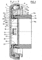
- la figure 1 est une vue en coupe axiale d'une butée de débrayage selon un aspect de l'invention ;
- la figure 2 est une vue en perspective de la bague de fixation;
- la figure 3 est une vue en perspective de la bague supplémentaire de fixation;
- la figure 4 est une demi-vue en coupe axiale d'une butée de débrayage selon un autre mode de réalisation de l'invention; et
- la figure 5 est une demi-vue en coupe axiale d'une butée de débrayage selon un autre mode de réalisation de l'invention.
- Figure 1 is an axial sectional view of a release stop according to one aspect of the invention;
- Figure 2 is a perspective view of the fixing ring;
- Figure 3 is a perspective view of the additional fixing ring;
- Figure 4 is a half-view in axial section of a release stop according to another embodiment of the invention; and
- Figure 5 is a half-view in axial section of a release stop according to another embodiment of the invention.
Comme on peut le voir sur la figure 1, la butée de débrayage comprend une bague non tournante de roulement 1 à paroi mince réalisée par emboutissage d'une tôle ou d'un tube présentant un chemin de roulement circulaire en forme de portion de tore 2 pour une rangée d'éléments roulants, ici des billes 3, ledit chemin présentant une section axiale méridienne à profil en arc de cercle concave. La bague intérieure 1 comporte une portion radiale 4 dirigée vers l'extérieur et une portion radiale 5 dirigée vers l'intérieur, lesdites portions radiales 4 et 5 étant disposées d'un côté et de l'autre des éléments roulants 3. La bague non tournante 1 est une bague intérieure. En variante, la bague non tournante 1 peut être une bague extérieure.As can be seen in FIG. 1, the clutch abutment comprises a thin-walled non-rotating bearing ring 1 made by stamping a sheet or tube having a circular portion-shaped
Le palier à roulement se complète par une bague extérieure 6 présentant une portion radiale 7 en saillie vers l'intérieur de l'ensemble et une portion cylindrique 8 du côté de la portion radiale 4. La portion radiale 7 est capable de venir en contact avec la surface d'un diaphragme ou d'un élément équivalent, non représenté, permettant l'actionnement d'un embrayage, notamment de véhicule automobile. La bague extérieure 6 comprend également une paroi mince qui peut être réalisée par emboutissage d'une tôle ou d'un tube. La bague extérieure 6 présente un chemin de roulement circulaire 9, en forme de portion de tore, pour la rangée d'éléments roulants 3, ledit chemin présentant en section axiale méridienne un profil en arc de cercle concave. Les éléments roulants 3 sont maintenus par une cage 10 entre le chemin de roulement 2 de la bague intérieure 1 et le chemin de roulement 9 de la bague extérieure 6. Le roulement à billes se complète par un organe d'étanchéité 11 monté de manière étanche dans la portion cylindrique 8 de la bague extérieure 5 et comprenant une armature 12 et une partie souple 13 venant frotter sur une portée cylindrique de la bague non tournante 1.The rolling bearing is completed by an
La butée de débrayage se complète par un élément de manoeuvre 16, visible sur la figure 2. L'élément de manoeuvre 16 peut être une pièce distincte de l'organe de commande actionnant le dispositif ou faire partie intégrante de celui-ci. L'élément de manoeuvre 16 peut être constitué, par exemple, par le piston hydraulique d'un dispositif de butée de débrayage à commande hydraulique.The clutch abutment is completed by an operating
La butée de débrayage comprend également un moyen de solidarisation axiale 17 entre l'élément de manoeuvre 16 et le roulement de butée, plus précisément la bague non tournante 1. Le moyen de solidarisation axiale 17 est du type permettant un certain déplacement radial de la bague non tournante 1 du roulement de butée par rapport à l'élément de manoeuvre 16.The clutch abutment also comprises an axial securing means 17 between the operating
Plus précisément, l'élément de manoeuvre 16 se présente sous la forme d'une portion de tube réalisée en matériau synthétique pourvu d'un alésage cylindrique et d'une surface extérieure 16a également cylindrique et entourée à une certaine distance par le ressort. Toutefois, l'extrémité de l'élément de manoeuvre 16, du côté du moyen de solidarisation axiale 17, présente un diamètre extérieur légèrement réduit avec un épaulement 16b et une rainure annulaire 16c. La rainure annulaire 16c ouverte vers l'extérieur peut présenter un rebord sensiblement radial à l'opposé de l'épaulement 16b. Une surface radiale 16d forme l'extrémité frontale de l'élément de manoeuvre 16 du côté du moyen de solidarisation axiale 17. L'alésage de l'élément de manoeuvre 16 est étagé et comprend une portion de grand diamètre 16e du côté du moyen de solidarisation axiale 17, un épaulement 16f, et une portion de petit diamètre 16g à l'opposé du moyen de solidarisation axiale 17.More specifically, the operating
Comme on peut le voir sur la figure 1, le moyen de solidarisation axiale 17 comprend une bague de fixation 18 et une bague supplémentaire 19, distinctes l'une de l'autre.As can be seen in Figure 1, the axial securing means 17 comprises a fixing
La bague de fixation 18 se présente sous la forme d'une pièce monobloc réalisée en tôle, de forme générale annulaire à section en L. La bague de fixation 18 comprend une portion annulaire axiale 20, et une portion axialement élastique 21. La portion axiale 20 est disposée dans l'alésage de la portion radiale 5 de la bague non tournante 1 et en contact avec la portion de grand diamètre 16e de l'alésage de l'élément de manoeuvre 16, axialement au niveau des éléments roulants 3. La portion axiale 20 fait saillie au-delà de la portion radiale 5 et se prolonge par la portion élastique 21. La différence de diamètre entre la portion axiale 20 et l'alésage de la portion radiale 5 autorise un certain déplacement radial du roulement de butée par rapport à l'élément de manoeuvre 16 et permet ainsi l'autoalignement du roulement par rapport au diaphragme de l'embrayage.The fixing
Dans la portion axiale 20, sont formées par découpe une pluralité de fenêtres 22 en forme de U, laissant subsister des languettes 23 présentant une certaine élasticité radiale, se rattachant à la portion axiale 20 du côté de son extrémité libre, à proximité de l'épaulement 16f. Les languettes 23 comprennent une extrémité libre 24 légèrement pliée en oblique vers l'extérieur. Les extrémités libres des languettes 23 sont dirigées vers la partie frontale de la butée. On entend par partie frontale de la butée, la partie destinée à venir en contact avec le diaphragme.In the
La portion élastique 21 s'étend vers l'extérieur à partir de la portion axiale 20 et présente un diamètre maximal supérieur l'alésage de la portion radiale 5 pour interférer avec ladite portion radiale 5. La portion élastique 21 présente une forme générale radiale, légèrement inclinée vers la portion radiale 5, avec une zone concave 21a du côté de la portion radiale 5 à proximité de la portion axiale 20, puis une zone tronconique 21b, puis une zone convexe 21c apte à venir en contact sur la portion radiale 5 avec de possibles glissements radiaux relatifs dus à l'autoalignement, et un rebord extérieur 21d déjeté à l'opposé de la portion radiale 5. Une pluralité de fenêtres 25 sont ménagées dans la portion élastique 21 sensiblement au niveau de la zone tronconique. Les fenêtres 25 permettent d'augmenter la souplesse axiale de la portion élastique 21.The
Alternativement, la portion élastique peut être découpée en une pluralité de languettes venant en contact avec la portion radiale 5. Les languettes peuvent être issues d'un bord intérieur et dirigées vers l'extérieur ou être issues d'un bord extérieur et dirigées vers l'intérieur.Alternatively, the elastic portion may be cut into a plurality of tongues coming into contact with the
La bague supplémentaire de fixation 19 se présente sous la forme d'une pièce monobloc réalisée en tôle emboutie, de forme générale annulaire à section en L. La bague supplémentaire 19 comprend une portion axiale annulaire 26, et une portion radiale annulaire 27 s'étendant vers l'intérieur à partir de la portion axiale 26 en faisant saillie au-delà de la portion de grand diamètre 16e de l'alésage de l'élément de manoeuvre 16. La portion radiale 27 sert de surface de butée aux extrémités libres 24 des languettes 23 pour le maintien axial de la bague de fixation 18. La portion radiale 27 est en contact d'un côté avec la surface frontale radiale d'extrémité de l'élément de manoeuvre 16 et les extrémités libres 24 des languettes 23, et de l'autre côté avec la portion radiale 5 de la bague non tournante 1.The
La portion axiale 26 est montée autour de l'extrémité libre de diamètre réduit de l'élément de manoeuvre 16. L'extrémité libre de la portion axiale 26 est située à faible distance de l'épaulement 16b. Dans la portion axiale 26, sont formées une pluralité de découpes en forme de U, laissant subsister autant de languettes 28 dont l'extrémité libre est dirigée axialement vers la portion radiale 27 et radialement vers l'intérieur. En d'autres termes, les découpes laissent subsister de la portion axiale 26, une portion annulaire continue, distante de la portion radiale 27, et une portion dans laquelle sont formées les languettes 28. La bague de fixation 18 et l'élément de manoeuvre 16 peuvent présenter des diamètres intérieurs sensiblement identiques.The
Les languettes 28 font saillie dans la rainure annulaire 16c avec leurs extrémités libres 28a venant en contact de butée contre la surface radiale de ladite rainure annulaire 16c du côté opposé à l'épaulement 16b. La bague supplémentaire 19 et l'élément de manoeuvre 16 peuvent présenter des diamètres extérieurs sensiblement identiques, afin d'éviter les aspérités susceptibles de nuire à la facilité de montage. La bague supplémentaire 19 et l'élément de manoeuvre 16 peuvent se fixer l'un sur l'autre par un simple mouvement axial. Les extrémités libres 28a des languettes 28 sont capables de s'effacer vers l'extérieur avant de rentrer dans la rainure annulaire 16c en reprenant au moins en partie leur position d'origine à l'état libre, garantissant ainsi la solidarisation de la bague supplémentaire 19 et de l'élément de manoeuvre 16, de façon sûre.The
Le montage peut s'effectuer de la façon suivante. On amène par un mouvement axial l'élément de manoeuvre 16 dans la bague supplémentaire 19, la portion axiale 26 entourant l'extrémité libre de diamètre réduit de l'élément de manoeuvre 16. Les languettes 28 s'effacent vers l'extérieur pour franchir le rebord de la rainure 16c, puis se rabattent vers l'intérieur par élasticité dans la rainure 16c en s'encliquetant.The assembly can be carried out as follows. The
On amène ensuite par un mouvement axial la bague non tournante 1, la portion radiale 5 venant en contact avec la portion radiale 27 de la bague supplémentaire 19. La portion axiale 26 se trouve alors sensiblement au niveau axial des éléments roulants 3.The non-rotating ring 1 is then moved axially, the
On amène ensuite par un mouvement axial la bague de fixation 18 du côté opposé de la portion radiale 5 de la bague non tournante 1. La portion axiale 20 passe dans l'alésage de la portion radiale 5 de la bague non tournante 1, dans l'extrémité libre de la portion radiale 27 de la bague supplémentaire 19 et dans la portion de grand diamètre 16e de l'élément de manoeuvre 16. Les languettes 23 s'effacent vers l'intérieur en franchissant l'extrémité libre de la portion radiale 27 de la bague supplémentaire 19. La portion élastique 21 entre en contact avec la portion radiale 5 de la bague non tournante 1.The fixing
Il est alors nécessaire d'exercer un certain effort axial pour déformer élastiquement la portion élastique 21 afin de poursuivre le mouvement axial. Les languettes 23 par élasticité s'écartent alors vers l'extérieur en contact avec l'alésage de la portion de grand diamètre 16e de l'élément de manoeuvre 16 après que les extrémités libres 24 des languettes 23 ont franchi l'extrémité libre de la portion radiale 27. Les extrémités libres 24 des languettes 23 alors entrent alors en contact de butée avec la portion radiale 27 empêchant ainsi une séparation de la bague de fixation 18, du sous-ensemble formé par la bague supplémentaire 19, la bague non tournante 1, et l'élément de manoeuvre 16. La bague non tournante 1 est maintenue axialement avec une légère précontrainte entre d'un côté la portion élastique 21, et de l'autre côté la portion radiale de la bague supplémentaire 19, tout en conservant un jeu radial grâce à la différence de diamètre entre la portion axiale 20 de la bague de fixation 18 et l'alésage de la portion radiale 5.It is then necessary to exert a certain axial force to elastically deform the
En variante, on peut prévoir d'amener l'élément de manoeuvre 16 en dernier sur un sous ensemble comprenant la bague non tournante 1, la bague de fixation 18 et la bague supplémentaire 19.As a variant, it is possible to bring the
On comprend que ce type de montage est particulièrement simple, avec un premier mouvement axial pour disposer la bague supplémentaire 19 sur l'élément de manoeuvre 16 et un second mouvement axial pour mettre en position la bague de fixation 18. On s'affranchit de toute étape de pliage d'un rebord lors de l'assemblage de ces éléments.It is understood that this type of assembly is particularly simple, with a first axial movement to arrange the
Dans le mode de réalisation illustré sur la figure 4, il est prévu en outre un organe d'étanchéité 29, de forme annulaire, comprenant une première portion axiale 29a disposée en contact avec l'alésage de la portion radiale 5 de la bague non tournante 1. La première portion axiale 29a peut être emmanchée ou simplement centrée dans ledit alésage. L'organe d'étanchéité 29 se complète par une portion radiale 29b en contact, d'un côté, avec la portion radiale 5 et, du côté opposé, avec le bord extérieur de la portion élastique 21 de la bague de fixation 18, et une deuxième portion axiale 29c dirigée à l'opposé de la portion radiale 5 et formant un passage étroit avec l'extrémité libre de la portion radiale 7 de la bague tournante 6 pour améliorer l'étanchéité du roulement. En d'autres termes, la bague de fixation 18 est en contact avec un élément monté sur la bague non tournante 1, cet élément assurant l'étanchéité entre les bagues tournante et non tournante.In the embodiment illustrated in FIG. 4, there is furthermore provided a ring-shaped sealing
Dans le mode de réalisation illustré sur la figure 5, la bague supplémentaire est supprimée. La portion radiale 5 de la bague non tournante 1 est en contact direct avec la surface radiale d'extrémité de l'élément de manoeuvre 16. L'élément de manoeuvre 16 est pourvu d'une nervure annulaire 16h en saillie vers l'intérieur, adjacente à la surface radiale d'extrémité, et limitant la portion de grand diamètre 16e. La nervure 16h sert de butée aux extrémités libres 24 des languettes 23. Un organe d'étanchéité 29 est prévu. Toutefois, on pourrait envisager un dispositif selon la figure 6 dépourvu d'organe d'étanchéité 29 comme celui de la figure 1. La surface extérieure 16a de l'élément de manoeuvre 16 est cylindrique.In the embodiment illustrated in Figure 5, the additional ring is removed. The
Grâce à l'invention, on réalise un système de fixation du roulement de butée et d'auto-centrage très compact et facile à assembler, même de façon automatique. De simples mouvements axiaux suffisent au montage qui est donc économique et fiable. L'élément de manoeuvre est de forme simple et donc robuste.Thanks to the invention, it achieves a fastening system of the thrust bearing and self-centering very compact and easy to assemble, even automatically. Simple axial movements are sufficient for mounting which is therefore economical and reliable. The operating element is simple in shape and therefore robust.
Claims (21)
- Clutch release bearing device, of the type comprising an operating element (16), a rolling bearing equipped with a non-rotating race (1) and a rotating race (6), the said rolling bearing being secured axially to the operating element (16), and an annular fixing ring (18) provided with a portion mounted in the operating element and with an axially elastic portion (21), the said fixing ring (18) being able to hold the non-rotating race axially secured to the operating element (16) while at the same time allowing radial movement, characterized in that the portion mounted in the operating element is an axial annular portion and is mounted in a bore of the operating element (16), the axially elastic portion bearing axially on the non-rotating race (1) on the side axially opposed to the operating element (16).
- Device according to Claim 1, characterized in that the said fixing ring (18) is in direct contact with the operating element.
- Device according to either one of the preceding claims, characterized in that the elastic portion (21) is substantially radial and is inclined towards the radial portion (5) of the non-rotating race (1).
- Device according to any one of the preceding claims, characterized in that the elastic portion (21) has a convex surface on the same side as the non-rotating race.
- Device according to any one of the preceding claims, characterized in that a plurality of holes (25) are formed in the elastic portion (21).
- Device according to any one of the preceding claims, characterized in that the elastic portion (21) comprises a plurality of axially elastic tabs.
- Device according to any one of the preceding claims, characterized in that the fixing ring (18) is of one piece.
- Device according to any one of the preceding claims, characterized in that the axial portion of the fixing ring (18) comprises fixing tabs (23) for fixing to the operating element.
- Device according to Claim 8, characterized in that the free end (24) of the fixing tabs (23) is in contact with a surface secured to the operating element.
- Device according to Claim 9, characterized in that the free end (24) of the fixing tabs is in contact with a substantially radial surface of the operating element.
- Device according to any one of the preceding claims, characterized in that it comprises an additional fixing ring (19) secured to the operating element.
- Device according to Claim 11, characterized in that the additional fixing ring (19) comprises an axial portion (26) and a radial portion (27) in contact with the operating element.
- Device according to Claim 12, characterized in that the radial portion (27) of the additional fixing ring (19) is in contact with the non-rotating race (1).
- Device according to Claim 12 or 13, characterized in that the additional fixing ring (19) comprises fixing tabs (28) for fixing to the operating element, the said tabs originating from the said axial portion (26).
- Device according to any one of Claims 12 to 14, characterized in that the axial portion (26) of the additional fixing ring (19) surrounds a part of the operating element.
- Device according to any one of Claims 11 to 15, characterized in that the additional fixing ring (19) comprises a retaining surface for retaining the fixing ring (18).
- Device according to any one of the preceding claims, characterized in that the non-rotating race (1) comprises an inwardly facing radial portion (4) arranged axially between the elastic portion (21) of the fixing ring (18) and a surface secured to the operating element (16).
- Device according to any one of the preceding claims, characterized in that the non-rotating race (1) is in direct contact with the elastic portion (21) of the fixing ring (18).
- Device according to any one of Claims 1 to 17, characterized in that it comprises a sealing element (29) secured to the non-rotating race and in contact with the elastic portion (21) of the fixing ring (18).
- Device according to any one of the preceding claims, characterized in that the operating element (16) is a hydraulic pusher.
- Clutch control system comprising a device according to any one of the preceding claims.
Applications Claiming Priority (2)
| Application Number | Priority Date | Filing Date | Title |
|---|---|---|---|
| FR0307356 | 2003-06-18 | ||
| FR0307356A FR2856448B1 (en) | 2003-06-18 | 2003-06-18 | STOP CLUTCH |
Publications (2)
| Publication Number | Publication Date |
|---|---|
| EP1489325A1 EP1489325A1 (en) | 2004-12-22 |
| EP1489325B1 true EP1489325B1 (en) | 2006-07-19 |
Family
ID=33396799
Family Applications (1)
| Application Number | Title | Priority Date | Filing Date |
|---|---|---|---|
| EP04290822A Expired - Lifetime EP1489325B1 (en) | 2003-06-18 | 2004-03-29 | Clutch release device |
Country Status (4)
| Country | Link |
|---|---|
| US (1) | US7222709B2 (en) |
| EP (1) | EP1489325B1 (en) |
| DE (1) | DE602004001550T2 (en) |
| FR (1) | FR2856448B1 (en) |
Families Citing this family (26)
| Publication number | Priority date | Publication date | Assignee | Title |
|---|---|---|---|---|
| FR2829429B1 (en) * | 2001-09-12 | 2003-12-12 | Skf Ab | STOP SUSPENSION DEVICE |
| FR2832201B1 (en) * | 2001-11-13 | 2004-03-19 | Skf Ab | INSTRUMENT TENSIONING DEVICE AND ASSOCIATED CONTROL METHOD |
| FR2835297B1 (en) | 2002-01-29 | 2004-04-16 | Skf Ab | FIXING SUPPORT, ROLLING BEARING AND ASSEMBLY METHOD THEREFOR |
| FR2841304B1 (en) | 2002-06-20 | 2007-01-05 | Skf Ab | VOLTAGE DEVICE FOR PRECONTRATING ROD AND ASSOCIATED VOLTAGE METHOD |
| FR2841990B1 (en) | 2002-07-02 | 2005-07-29 | Skf Ab | INSTRUMENTAL BEARING BEARING DEVICE AND ELECTRIC MOTOR THUS EQUIPPED |
| FR2851624B1 (en) | 2003-02-26 | 2006-03-31 | Skf Ab | INSTRUMENT BEARING BEARING |
| FR2853065B1 (en) * | 2003-03-27 | 2006-01-06 | Skf Ab | PORTABLE MEASURING INSTRUMENT, PARTICULARLY FOR SPORT PRACTICE. |
| FR2853165B1 (en) * | 2003-03-27 | 2005-12-02 | Skf Ab | SENSOR ASSEMBLY, AND HOUSING FOR CARRYING OUT SUCH AN ASSEMBLY. |
| FR2856757B1 (en) * | 2003-06-27 | 2006-10-20 | Skf Ab | INSTRUMENT BEARING BEARING AND ENCODER FOR INFORMATION SENSOR ASSEMBLY |
| FR2858376B1 (en) * | 2003-07-28 | 2006-03-03 | Skf France | FREEWHEEL BEARING DEVICE WITH TORQUE LIMITER. |
| FR2861459B1 (en) * | 2003-10-22 | 2006-02-24 | Skf Ab | ABSOLUTE MULTITOUR HIGH RESOLUTION ROTATION MEASUREMENT SYSTEM AND BEARING EQUIPPED WITH SUCH A SYSTEM. |
| FR2872558B1 (en) * | 2004-07-02 | 2006-09-29 | Skf Ab | CLUTCH FASTER AND METHOD OF MANUFACTURE |
| FR2882580B1 (en) * | 2005-02-28 | 2007-05-25 | Skf Ab | INSTRUMENT BELT TENSIONER ROLLING DEVICE AND METHOD OF CONTROLLING THE SAME |
| DE102005053612A1 (en) * | 2005-11-10 | 2007-05-16 | Schaeffler Kg | Release bearing for an actuator of a clutch |
| FR2902699B1 (en) | 2006-06-26 | 2010-10-22 | Skf Ab | SUSPENSION STOP DEVICE AND FORCE LEG. |
| FR2906587B1 (en) | 2006-10-03 | 2009-07-10 | Skf Ab | TENDERING ROLLER DEVICE. |
| FR2908852B1 (en) * | 2006-11-22 | 2012-07-13 | Roulements Soc Nouvelle | CONTROLLED TORQUE SUSPENSION STOP AND VEHICLE DIRECTION CONTROL WHEEL SUSPENSION LEG. |
| FR2913081B1 (en) | 2007-02-27 | 2009-05-15 | Skf Ab | DEBRAYABLE PULLEY DEVICE |
| FR2936032B1 (en) * | 2008-09-16 | 2011-08-26 | Skf Ab | BEARING, ITS USE AND MOTOR VEHICLE EQUIPPED WITH SUCH A BEARING. |
| DE102012200619A1 (en) * | 2012-01-17 | 2013-07-18 | Schaeffler Technologies AG & Co. KG | Rolling bearing assembly, in particular Aurücklageranordnung |
| EP2809470B1 (en) | 2012-02-03 | 2020-01-15 | Milwaukee Electric Tool Corporation | Rotary hammer |
| DE102012206449B4 (en) | 2012-04-19 | 2019-10-17 | Schaeffler Technologies AG & Co. KG | Planetary gear with integrated bearing inner ring |
| CN104169613B (en) | 2012-04-19 | 2017-11-28 | 舍弗勒技术股份两合公司 | Planetary gear mechanism with differential mechanism |
| DE102016204500B3 (en) * | 2016-03-18 | 2017-08-03 | Schaeffler Technologies AG & Co. KG | release bearing |
| DE102016207088A1 (en) * | 2016-04-26 | 2017-10-26 | Schaeffler Technologies AG & Co. KG | Slave cylinder for a clutch actuation unit |
| KR102132347B1 (en) * | 2019-01-29 | 2020-07-09 | 셰플러코리아(유) | A Clutch Release Bearing |
Family Cites Families (15)
| Publication number | Priority date | Publication date | Assignee | Title |
|---|---|---|---|---|
| FR2384990A1 (en) | 1977-03-25 | 1978-10-20 | Skf Cie Applic Mecanique | ELASTIC SELF-ALIGNING CLUTCH STOPPER WITH GUIDING MEANS |
| FR2461158A1 (en) | 1979-07-10 | 1981-01-30 | Skf Cie Applic Mecanique | SELF-CENTERING CLUTCH STOP |
| FR2577291B1 (en) * | 1985-02-08 | 1989-10-13 | Valeo | SELF-CENTERING CLUTCH STOPPER, PARTICULARLY FOR MOTOR VEHICLE, WITH SIMPLIFIED COMPACT ASSEMBLY |
| FR2611244B1 (en) * | 1987-02-20 | 1991-07-05 | Valeo | RELEASE CLUTCH WITH ELASTIC PIECE WITH AXIAL ACTION, IN PARTICULAR FOR A MOTOR VEHICLE |
| JPS63246516A (en) | 1987-04-02 | 1988-10-13 | Nippon Seiko Kk | Clutch release bearing device |
| FR2645929B1 (en) * | 1989-04-18 | 1991-06-07 | Roulements Soc Nouvelle | DEVICE FOR CLAMPING A THRUST BEARING ON A SLIDING SUPPORT |
| JPH06213251A (en) | 1993-01-20 | 1994-08-02 | Koyo Seiko Co Ltd | Self-aligning type clutch release bearing device |
| FR2730534B1 (en) * | 1995-02-09 | 1997-04-04 | Valeo | HYDRAULICALLY CONTROLLED CLUTCH STOPPER FOR A MOTOR VEHICLE DIAPHRAGM CLUTCH |
| US6415900B1 (en) * | 1996-12-23 | 2002-07-09 | Valeo | Hydraulic control receiver with closing plate |
| DE19716218C2 (en) | 1997-04-18 | 2001-08-30 | Schaeffler Waelzlager Ohg | Clutch release bearing |
| FR2772444B1 (en) | 1997-12-11 | 2000-06-16 | Valeo | HYDRAULIC RECEIVER FOR CLUTCH CONTROL, PARTICULARLY FOR MOTOR VEHICLE |
| FR2807802B1 (en) * | 2000-04-12 | 2002-07-26 | Skf France | RELEASE STOP AND DRIVING ELEMENT FOR RELEASE STOP |
| US7117986B2 (en) | 2000-12-22 | 2006-10-10 | Valeo Embrayages | Clutch release bearing, in particular for motor vehicle |
| FR2819864B1 (en) | 2001-01-23 | 2003-04-25 | Skf Ab | SELF-CENTERING RELEASE STOP DEVICE |
| DE10148388A1 (en) | 2001-09-29 | 2003-04-24 | Ina Schaeffler Kg | Roller bearing for a clutch disengagement unit, comprises a rotating ring, a fixed ring, an inner chamber and ball bearings |
-
2003
- 2003-06-18 FR FR0307356A patent/FR2856448B1/en not_active Expired - Fee Related
-
2004
- 2004-03-29 EP EP04290822A patent/EP1489325B1/en not_active Expired - Lifetime
- 2004-03-29 DE DE602004001550T patent/DE602004001550T2/en not_active Expired - Lifetime
- 2004-06-17 US US10/870,483 patent/US7222709B2/en not_active Expired - Fee Related
Also Published As
| Publication number | Publication date |
|---|---|
| DE602004001550D1 (en) | 2006-08-31 |
| EP1489325A1 (en) | 2004-12-22 |
| US7222709B2 (en) | 2007-05-29 |
| FR2856448B1 (en) | 2006-09-01 |
| DE602004001550T2 (en) | 2007-07-05 |
| US20050011717A1 (en) | 2005-01-20 |
| FR2856448A1 (en) | 2004-12-24 |
Similar Documents
| Publication | Publication Date | Title |
|---|---|---|
| EP1489325B1 (en) | Clutch release device | |
| EP1489327B1 (en) | Clutch release device and method of assembly | |
| EP1225360B1 (en) | Self-centering device for a clutch release mechanism | |
| EP0941414B1 (en) | Rolling bearing of steering column for motor vehicles | |
| FR2860847A1 (en) | Throw-out bearing device for automobile vehicle, has self-aligning sleeve with fibers that are directed towards interior and axial portion fitted in central opening of radial portion of ring | |
| EP1146244B1 (en) | Clutch release bearing | |
| FR2883347A1 (en) | Disengaging bearing device for a motor vehicle's clutch has a fixed ring, a rotating ring and a plastic thrust ring joined to the rotating ring | |
| FR2619880A1 (en) | RELEASE STOP, IN PARTICULAR FOR MOTOR VEHICLES | |
| FR2898951A1 (en) | SELF-CENTERING CLUTCH | |
| EP1988002B1 (en) | Rolling bearing device for a steering column | |
| FR2961280A1 (en) | CLUTCH FASTENING DEVICE COMPRISING A WEAR RING. | |
| EP0806581B1 (en) | Clutch release bearing with an resilient ring | |
| FR2971825A1 (en) | Rolling bearing for use in clutch release bearing device arranged on diaphragm of clutch of motor vehicle, has metallic rigid stop portions cooperating by contact with rolling elements to limit angular tilting of movable outer ring | |
| EP0770789B1 (en) | Hydraulic clutch-actuating device | |
| FR2459906A1 (en) | Clutch thrust bearing assembly - has wear plate arms forming elastic clamps for bearing race and guide sleeve | |
| FR2760057A1 (en) | FREE WHEEL DEVICE WITH RETAINING FLANGE AND METHOD FOR PLACING THE FLANGE | |
| FR2856122A1 (en) | Clutch throw-out bearing, has axial retaining strip connected directly on bead and having retaining units with control unit, at its free end, where strip traverses opening in radial flange of operating device | |
| FR2872235A1 (en) | Clutch release bearing device for motor vehicle, has retention ring with lugs engaged in axial portion openings of fixation ring to fix rings, and washer pre-stressed between former ring and radial portion of non-rotating ring of bearing | |
| FR2876170A1 (en) | SELF-BREAKING CLUTCH FASTENING AND MOUNTING METHOD | |
| EP0965004B1 (en) | Clutch thrust block | |
| FR2693523A1 (en) | Clutch thrust bearing of pulled type - has components for automatically centring bearing on drive shaft | |
| FR2911939A1 (en) | Clutch releasing unit arrangement for motor vehicle, has axial safety device with disk formed with guides and area elongating guides, where operating unit is provided with insert, which is fixed to operating unit and contacts with guides | |
| EP0926375B1 (en) | Clutch release bearing with lateral guiding and connecting clips | |
| FR2745051A1 (en) | The mounting of clutch thrust bearing for motor vehicles | |
| FR2723995A1 (en) | Auto centring clutch thrust bearing |
Legal Events
| Date | Code | Title | Description |
|---|---|---|---|
| PUAI | Public reference made under article 153(3) epc to a published international application that has entered the european phase |
Free format text: ORIGINAL CODE: 0009012 |
|
| AK | Designated contracting states |
Kind code of ref document: A1 Designated state(s): AT BE BG CH CY CZ DE DK EE ES FI FR GB GR HU IE IT LI LU MC NL PL PT RO SE SI SK TR |
|
| AX | Request for extension of the european patent |
Extension state: AL HR LT LV MK |
|
| 17P | Request for examination filed |
Effective date: 20050114 |
|
| 17Q | First examination report despatched |
Effective date: 20050330 |
|
| AKX | Designation fees paid |
Designated state(s): DE FR GB IT |
|
| GRAP | Despatch of communication of intention to grant a patent |
Free format text: ORIGINAL CODE: EPIDOSNIGR1 |
|
| GRAS | Grant fee paid |
Free format text: ORIGINAL CODE: EPIDOSNIGR3 |
|
| GRAA | (expected) grant |
Free format text: ORIGINAL CODE: 0009210 |
|
| AK | Designated contracting states |
Kind code of ref document: B1 Designated state(s): DE FR GB IT |
|
| PG25 | Lapsed in a contracting state [announced via postgrant information from national office to epo] |
Ref country code: IT Free format text: LAPSE BECAUSE OF FAILURE TO SUBMIT A TRANSLATION OF THE DESCRIPTION OR TO PAY THE FEE WITHIN THE PRESCRIBED TIME-LIMIT;WARNING: LAPSES OF ITALIAN PATENTS WITH EFFECTIVE DATE BEFORE 2007 MAY HAVE OCCURRED AT ANY TIME BEFORE 2007. THE CORRECT EFFECTIVE DATE MAY BE DIFFERENT FROM THE ONE RECORDED. Effective date: 20060719 Ref country code: GB Free format text: LAPSE BECAUSE OF FAILURE TO SUBMIT A TRANSLATION OF THE DESCRIPTION OR TO PAY THE FEE WITHIN THE PRESCRIBED TIME-LIMIT Effective date: 20060719 |
|
| REG | Reference to a national code |
Ref country code: GB Ref legal event code: FG4D Free format text: NOT ENGLISH |
|
| REF | Corresponds to: |
Ref document number: 602004001550 Country of ref document: DE Date of ref document: 20060831 Kind code of ref document: P |
|
| GBV | Gb: ep patent (uk) treated as always having been void in accordance with gb section 77(7)/1977 [no translation filed] |
Effective date: 20060719 |
|
| PLBE | No opposition filed within time limit |
Free format text: ORIGINAL CODE: 0009261 |
|
| STAA | Information on the status of an ep patent application or granted ep patent |
Free format text: STATUS: NO OPPOSITION FILED WITHIN TIME LIMIT |
|
| 26N | No opposition filed |
Effective date: 20070420 |
|
| PGFP | Annual fee paid to national office [announced via postgrant information from national office to epo] |
Ref country code: FR Payment date: 20120406 Year of fee payment: 9 |
|
| PGFP | Annual fee paid to national office [announced via postgrant information from national office to epo] |
Ref country code: IT Payment date: 20120326 Year of fee payment: 9 |
|
| REG | Reference to a national code |
Ref country code: FR Ref legal event code: ST Effective date: 20131129 |
|
| PG25 | Lapsed in a contracting state [announced via postgrant information from national office to epo] |
Ref country code: FR Free format text: LAPSE BECAUSE OF NON-PAYMENT OF DUE FEES Effective date: 20130402 |
|
| PG25 | Lapsed in a contracting state [announced via postgrant information from national office to epo] |
Ref country code: IT Free format text: LAPSE BECAUSE OF NON-PAYMENT OF DUE FEES Effective date: 20130329 |
|
| PGFP | Annual fee paid to national office [announced via postgrant information from national office to epo] |
Ref country code: DE Payment date: 20150601 Year of fee payment: 12 |
|
| REG | Reference to a national code |
Ref country code: DE Ref legal event code: R119 Ref document number: 602004001550 Country of ref document: DE |
|
| PG25 | Lapsed in a contracting state [announced via postgrant information from national office to epo] |
Ref country code: DE Free format text: LAPSE BECAUSE OF NON-PAYMENT OF DUE FEES Effective date: 20161001 |