EP1489035A2 - Antrieb für eine Fahrtreppe - Google Patents
Antrieb für eine Fahrtreppe Download PDFInfo
- Publication number
- EP1489035A2 EP1489035A2 EP04009186A EP04009186A EP1489035A2 EP 1489035 A2 EP1489035 A2 EP 1489035A2 EP 04009186 A EP04009186 A EP 04009186A EP 04009186 A EP04009186 A EP 04009186A EP 1489035 A2 EP1489035 A2 EP 1489035A2
- Authority
- EP
- European Patent Office
- Prior art keywords
- shaft
- drive according
- escalator
- drive
- chain links
- Prior art date
- Legal status (The legal status is an assumption and is not a legal conclusion. Google has not performed a legal analysis and makes no representation as to the accuracy of the status listed.)
- Withdrawn
Links
Images


Classifications
-
- B—PERFORMING OPERATIONS; TRANSPORTING
- B66—HOISTING; LIFTING; HAULING
- B66B—ELEVATORS; ESCALATORS OR MOVING WALKWAYS
- B66B23/00—Component parts of escalators or moving walkways
- B66B23/02—Driving gear
Definitions
- the present invention relates to a drive for an escalator, comprising at least one wave.
- a drive of the aforementioned type is known from DE 697 16 584 T2 known.
- the drive described in this document includes a motor on which a drive gear is arranged.
- On the A drive chain is held around the circumference of the drive gear around a coaxial to the drive gear on a shaft Gear runs.
- There are sprockets for one on this shaft Conveyor track arranged in one for escalators or moving walks is constructed in a known manner.
- the conveyor track is with conveyor chains provided that revolve around the sprockets. At this The conveyor chains are arranged by the sprockets driven and redirected around it at the same time. The conveyor chains are fed tangentially to the sprockets. This will point the conveyor chains and the sprockets when the Sprockets different in the respective conveyor chain Speeds up, causing bumps toward the free running part of the conveyor chains comes.
- the drive and the deflection of the conveyor chain by means of a Chain gear occurring polygon and recirculation effects negatively affect the smooth running of the escalator in particular.
- the polygon and circulation effects lead to high loads on the conveyor chains, the sprockets and the drive.
- the polygon and orbital effects increase Increase in conveyor speed of the escalator.
- Farther escalators driven in this way require a large installation space, to accommodate all the necessary components of the drive can.
- Differences in height serve, as in multi-storey department stores is provided, due to the installation depth of the escalator and corresponding ceiling heights of the associated drive to be provided in order to be able to install the escalator.
- the object of the present invention is to provide a drive for a To provide escalator, the space-saving installation of the Escalator enables and to reduce the polygon and Contributes to circulation effects.
- the shaft at least is designed in sections like a snail.
- the usage an at least partially designed like a snail Shaft for transferring a feed movement to the one to be driven
- Components of the escalator contribute to a reduction in the number of Deflection devices and the components to be driven occurring polygon and circulation effects.
- the Deflection devices have a substantially equal speed on how to drive the components of the escalator.
- the deflection devices of the driven components of the escalator are driven.
- the components of the escalator are driven by the shaft, which is a substantially constant speed on the Components of the escalator transfers, the inventive Drive higher conveyor speeds and an increase in Allows chain splitting without the polygon and wrap effects strengthen.
- Conveyor speed of the escalator can be greater than 0.5 m / s his.
- the shaft can be designed as a worm shaft.
- the shaft can preferably extend in the longitudinal direction of the escalator extend.
- the shaft is preferably arranged below of the accessible walk-in area of the escalator between the deflection devices. This makes the dimensions the machine rooms at the end of the escalator present invention, which in conventional escalators Housing one or more engines that Deflection devices and the drive means are used, smaller than required in the prior art.
- Arrangement of the shaft help increase the depth of the escalator reduce, resulting in a space-saving installation of the escalator is possible.
- the shaft can preferably be designed as a shaft with a helical helix welded onto it. Furthermore, the shaft can be designed as a shaft with a groove turned helically out of the shaft. Likewise, the manufacture of the shaft with such a turn can be carried out by milling or other suitable manufacturing processes. Furthermore, the shaft can be connected directly or indirectly to a motor. In this way, existing spatial and structural framework conditions can be better taken into account and used, under which the escalator is to be installed.
- the escalator can preferably have at least one funding include that can be driven by the shaft.
- the Funding is used to transfer the feed movement to the components of the escalator to be driven.
- it can Funding can be carried out substantially chain-like, the Funding in particular as an endless chain around deflection devices can be arranged circumferentially.
- the funding can be articulated Include chain links, the chain links releasably together can be connected. This will make the Funding increases, because in this way individual chain links of the funding replaced.
- the Chain links are essentially cranked.
- a plurality of chain links or each of the Chain links each have at least one feed means.
- the feed means can be detachably arranged on the chain link, what the simple exchange of individual feed means in Repairs allowed.
- the feed means on the Winding of the shaft facing side of the chain link arranged be, where it can be engaged with the turn.
- Farther can have a stair plate that can be swiveled around the axis be arranged.
- the stair plate can accommodate up to serve transporting persons and / or objects.
- At least two feed means can advantageously be used at the same time mesh with the shaft. Is that for example Feed means of a chain link on the last turn in Direction of conveyance of the shaft, this is at the same time Feed means of the subsequent chain link essentially in the middle of the shaft and is engaged with its winding.
- the drive can preferably be at least two parallel to one another arranged, at least partially snail-like waves exhibit.
- the waves each drive a subsidy, which are also arranged parallel to each other.
- One is in particular Device for synchronizing the drive provided to the Waves transmit the same torque and the same time The waves start up when the escalator is put into operation guarantee.
- the drive can advantageously be at least two in a row Row arranged, at least in sections snail-like Have shafts that are each connected to a motor. Consequently can apply greater torque from the waves to the escalator be transmitted. This is beneficial for escalators with which larger distances should be overcome, such as this when using moving walkways at airports.
- the turns can be parallel to each other arranged waves to be executed in opposite ascending order.
- the shafts arranged parallel to each other can pass through the Stair plates must be connected to each other.
- By using it one with a left-handed and one with a right-handed Winding wave will be the most on the funding acting transverse forces on the between the funds arranged stair plates transferred.
- the on the stair plates Transmitted lateral forces are opposite to each other and largely compensate each other. This helps increase The escalator runs smoothly.
- the escalator can preferably be used as an escalator or as a moving walkway be executed.
- the drive according to the invention Use with escalators used for the transportation of people or find moving walkways. For escalators for the promotion of people stands next to a high conveying speed Escalator the smooth running in the foreground. These requirements can be fulfilled by the drive according to the invention.
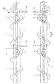
- the representation is the part of an escalator drive essential to the invention, especially for the drive of an escalator or one Escalator is provided.
- the escalator drive includes at least one with a helical turn Shaft, in particular a worm shaft 1, and at least one funding driven by the worm shaft 1 2.
- Die Worm shaft 1 is with at least one motor, not shown connected, the drive torque to the worm shaft 1 transfers.
- the direction of conveyance of the escalator is indicated by the arrow F illustrated.
- the conveyor 2 is essentially chain-shaped and runs at least two spaced apart Deflection devices endless.
- the arrangement of the funding 2 is essentially parallel to the longitudinal axis of the worm shaft 1.
- the funding 2 extends essentially over the entire Length of the escalator.
- the funding 2 comprises a plurality articulated chain links 3.
- Fig. 1 are two chain links 3 of the conveyor 2 are shown as examples.
- Each chain link 3 has its worm shaft 1 facing side at least one feed means 5, which Feed means 5 at least in sections on a flank 6 of the Winding of the worm shaft 1 is present.
- the feed means 5 comprises a substantially annular race 7, with her outer circumference on the flank 6 of the turn.
- the Runner 7 is arranged on a fastening bolt 8 and rotatably mounted on this.
- the mounting bolt 8 is with his end facing away from the running disk 7 with the chain link 3 connected, for example by a screw connection.
- the spacing of the feed means 5 from the feed means 5 of the adjacent chain links 3 is such that always at least two feed means 5 with the winding of the worm shaft 1 in Stand by.
- Fig. 2 shows a top view of the escalator drive.
- the two worm shafts 1 arranged parallel to each other are each with a conveyor 2 to be driven, which essentially are arranged parallel to each other.
- the chain links 3 are through Axes 10 pivotally connected to each other.
- the arrangement of the axes 10 is such that it extends horizontally across the Windings of the worm shafts 1 extending ends of the Axes 10 are facing each other.
- Between funding 2 are arranged on the axes 10 stair plates, not shown. The stair plates are pivoted about the axes 10.
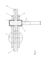
- FIG. 3 shows two chain links 3 of the conveying means 2 shown in sections in partial section.
- the representation are the end portions of adjacent chain links 3 can be seen.
- tabs 4 are arranged, these connect with each other in an articulated manner.
- the tabs 4 preferably in pairs, substantially parallel to each other Chain links 3 extending on the outer sides of each other facing end sections of the adjacent chain links 3 arranged.
- the tabs 4 overlap in sections adjacent chain links 3, the end portions of the adjacent chain links 3 arranged between the plates 4 are.
- the chain links 3 have an axle bore 11 at one end, through which the axis 10 extends.
- the axis 10 extends horizontally at an angle of approximately 90 ° to the longitudinal axis of the Worm shaft 1.
- the length of the axis 10 is such that the axis 10 extends in sections horizontally beyond the flank 6.
- the Bearing bush 9 is with a plain bearing, needle bearing or the like executed in which the axis 10 is rotatably mounted.
- the camp is sealed as a maintenance-free bearing, but it is also a unsealed bearing can be used.
- the illustration shows the end sections adjacent Chain links 3.
- the chain links 3 are at least in sections hook-shaped, so-called cranked Chain links 3.
- the mutually facing sides of the previous one Chain link pair 12 facing sections of the Chain link pair 12 essentially abut each other.
- the mutually facing sides of the following Sections of chain link 12 facing each other are such spaced that these are essentially adjacent Sections of the subsequent chain link pair 12 at least overlap in sections.
- the feed movement of the escalator in the direction of conveyance F is determined by a transmitted from the motor to the worm shaft 1 Torque caused.
- the rotating movement of the Auger shaft 1 in a substantially rectilinear movement of the Funding 2 converted.
- the rotation of the worm shaft 1 by their longitudinal axis causes the feed means 5, the Runner 7 rests on the flank 6 of the turn and on this rolls, is moved in the conveying direction F. This movement is from the feed means 5 on the mounting bolt 8 on the transfer each chain link 3 of the conveyor 2.
- To be a continuous To ensure feed movement of the escalator always at least two feed means 5 between the flanks 6 in order the rotational movement of the worm shaft 1 on the feed means 5 transfer.
- the feed means 5 of a chain link 3 is located on the last turn in the direction of conveyance F Worm shaft 1, there is also the feed means 5 a chain link 3 offset by a chain link 3 in the first Winding path on the side facing away from the conveying direction F. the worm shaft 1.
- Escalator drive with a worm shaft 1 and one Subsidies 2 include shear forces, which cause that the chain links 3 at an angle to the longitudinal axis of the Worm shaft 1 are subjected to shear forces.
- each other Worm shafts 1 are provided, each of which is a conveyor 2 drive (see Fig. 2).
- the funding 2 are due to each other opposite axes 10 of the chain links 3 attached Stair plates non-positively connected to each other.
- the turns of the worm shafts 1 are opposite executed in ascending order.
- the winding of a worm shaft 1 rises in the direction of conveyance F from left to right, i.e. the swirl is clockwise while the other worm shaft 1 rises in the conveying direction F from right to left, thus left-handed is.
Landscapes
- Escalators And Moving Walkways (AREA)
Abstract
Description
Des weiteren kann die Welle mittelbar oder unmittelbar mit einem Motor verbunden sein. Somit können vorliegende räumliche und bauliche Rahmenbedingungen besser berücksichtigt und ausgenutzt werden, unter denen die Fahrtreppe eingebaut werden soll.
- Fig. 1
- eine Seitenansicht eines erfindungsgemäßen Fahrtreppenantriebs;
- Fig. 2
- eine Draufsicht auf den Fahrtreppenantrieb;
- Fig. 3
- eine Teilschnittansicht eines Fördermittels des Fahrtreppenantriebs gemäß der Einzelheit III in Fig. 2;
- Fig. 4
- eine Teilschnittansicht einer weiteren Ausführungsform des Fördermittels.
Claims (22)
- Antrieb für eine Fahrtreppe umfassend mindestens eine Welle, dadurch gekennzeichnet, dass die Welle zumindest abschnittsweise schneckenähnlich ausgebildet ist.
- Antrieb nach Anspruch 1, dadurch gekennzeichnet, dass die Welle als Schneckenwelle (1) ausgeführt ist.
- Antrieb nach einem der Ansprüche 1 oder 2, dadurch gekennzeichnet, dass die Welle sich in Längsrichtung der Fahrtreppe erstreckt.
- Antrieb nach einem der Ansprüche 1 bis 3, dadurch gekennzeichnet, dass die Welle mit einer aufgeschweißten schneckenförmigen Wendel ausgeführt ist.
- Antrieb nach einem der Ansprüche 1 bis 3, dadurch gekennzeichnet, dass die Welle mit einer schneckenförmig aus der Welle gedrehten Nut ausgeführt ist.
- Antrieb nach einem der Ansprüche 1 bis 5, dadurch gekennzeichnet, dass die Welle mittelbar oder unmittelbar mit einem Motor verbunden ist.
- Antrieb nach einem der Ansprüche 1 bis 6, dadurch gekennzeichnet, dass die Fahrtreppe mindestens ein Fördermittel (2) umfasst, das von der Welle angetrieben werden kann.
- Antrieb nach Anspruch 7, dadurch gekennzeichnet, dass das Fördermittel (2) im Wesentlichen kettenförmig ausgeführt ist.
- Antrieb nach einem der Ansprüche 7 oder 8, dadurch gekennzeichnet, dass das Fördermittel (2) gelenkig miteinander verbundene Kettenglieder (3) umfasst.
- Antrieb nach Anspruch 9, dadurch gekennzeichnet, dass die Kettenglieder (3) lösbar miteinander verbunden sind.
- Antrieb nach einem der Ansprüche 9 oder 10, dadurch gekennzeichnet, dass die Kettenglieder (3) im Wesentlichen gekröpft ausgeführt sind.
- Antrieb nach einem der Ansprüche 9 bis 11, dadurch gekennzeichnet, dass eine Mehrzahl von Kettengliedern (3) oder jedes der Kettenglieder (3) jeweils mindestens ein Vorschubmittel (5) aufweist.
- Antrieb nach Anspruch 12, dadurch gekennzeichnet, dass das Vorschubmittel (5) auf der der Welle zugewandten Seite des Kettengliedes (3) angeordnet ist.
- Antrieb nach einem der Ansprüche 12 oder 13, dadurch gekennzeichnet, dass das Vorschubmittel (5) an dem Kettenglied (3) angeordnet ist.
- Antrieb nach einem der Ansprüche 9 bis 14, dadurch gekennzeichnet, dass an den Kettenglieder (3) eine sich senkrecht zur Längsachse der Welle erstreckende Achse (10) angeordnet ist.
- Antrieb nach Anspruch 15, dadurch gekennzeichnet, dass an der Achse (10) eine um die Achse (10) schwenkbare Treppenplatte angeordnet ist.
- Antrieb nach einem der Ansprüche 12 bis 16, dadurch gekennzeichnet, dass mindestens zwei Vorschubmittel (5) mit der Welle in Eingriff stehen.
- Antrieb nach einem der Ansprüche 1 bis 17, dadurch gekennzeichnet, dass der Antrieb mindestens zwei parallel zueinander angeordnete, zumindest abschnittsweise schneckenähnliche Wellen aufweist.
- Antrieb nach einem der Ansprüche 1 bis 18, dadurch gekennzeichnet, dass der Antrieb mindestens zwei hintereinander in Reihe angeordnete, zumindest abschnittsweise schneckenähnliche Wellen aufweist.
- Antrieb nach einem der Ansprüche 18 oder 19, dadurch gekennzeichnet, dass die Windungen parallel angeordneter Wellen entgegengesetzt aufsteigend ausgeführt sind.
- Antrieb nach einem der Ansprüche 18 bis 20, dadurch gekennzeichnet, dass die Wellen durch die Treppenplatten miteinander verbunden sind.
- Antrieb nach einem der Ansprüche 1 bis 21, dadurch gekennzeichnet, dass die Fahrtreppe als Rolltreppe oder als Rollsteig ausgeführt ist.
Applications Claiming Priority (2)
| Application Number | Priority Date | Filing Date | Title |
|---|---|---|---|
| DE2003127642 DE10327642A1 (de) | 2003-06-20 | 2003-06-20 | Antrieb für eine Fahrtreppe |
| DE10327642 | 2003-06-20 |
Publications (2)
| Publication Number | Publication Date |
|---|---|
| EP1489035A2 true EP1489035A2 (de) | 2004-12-22 |
| EP1489035A3 EP1489035A3 (de) | 2006-05-17 |
Family
ID=33394883
Family Applications (1)
| Application Number | Title | Priority Date | Filing Date |
|---|---|---|---|
| EP04009186A Withdrawn EP1489035A3 (de) | 2003-06-20 | 2004-04-17 | Antrieb für eine Fahrtreppe |
Country Status (2)
| Country | Link |
|---|---|
| EP (1) | EP1489035A3 (de) |
| DE (1) | DE10327642A1 (de) |
Cited By (3)
| Publication number | Priority date | Publication date | Assignee | Title |
|---|---|---|---|---|
| WO2012130993A1 (de) | 2011-04-01 | 2012-10-04 | Daniel Mertl | Beförderungsmittel, mit zumindest einem transportelement und einem antriebssystem für das transportelement |
| ES2452815A1 (es) * | 2013-09-23 | 2014-04-02 | Thyssenkrupp Elevator Innovation Center, S. A. | Sistema para arrastre de pasamanos de pasillos y escaleras móviles |
| US20220332544A1 (en) * | 2021-04-15 | 2022-10-20 | Taizhou University | Elevating apparatus based on hetero-oriented, non-isometric, dual-spiral drive structure |
Family Cites Families (7)
| Publication number | Priority date | Publication date | Assignee | Title |
|---|---|---|---|---|
| GB190922563A (en) * | 1909-10-04 | 1910-07-28 | Benjamin Ratcliffe Adkins | Improvements in Conveying Apparatus. |
| DE1456375A1 (de) * | 1966-04-14 | 1968-12-12 | Orenstein & Koppel Ag | Antrieb fuer Rolltreppen |
| CA968735A (en) * | 1972-01-14 | 1975-06-03 | Goodyear Tire And Rubber Company (The) | Passenger conveyor |
| DE2541397C3 (de) * | 1975-09-17 | 1979-06-21 | O & K Orenstein & Koppel Ag, 1000 Berlin | Antriebseinheit fur Rolltreppen |
| JP2547631B2 (ja) * | 1988-12-28 | 1996-10-23 | 株式会社間組 | 変速型搬送機 |
| US6170632B1 (en) * | 1997-10-14 | 2001-01-09 | Ishikawajima-Harima Jukogyo Kabushiki Kaisha | Moving walk |
| US6273235B1 (en) * | 1998-11-12 | 2001-08-14 | Fujitec America, Inc. | Flexible drive system for escalators or moving walks |
-
2003
- 2003-06-20 DE DE2003127642 patent/DE10327642A1/de not_active Ceased
-
2004
- 2004-04-17 EP EP04009186A patent/EP1489035A3/de not_active Withdrawn
Cited By (7)
| Publication number | Priority date | Publication date | Assignee | Title |
|---|---|---|---|---|
| WO2012130993A1 (de) | 2011-04-01 | 2012-10-04 | Daniel Mertl | Beförderungsmittel, mit zumindest einem transportelement und einem antriebssystem für das transportelement |
| AT511233A1 (de) * | 2011-04-01 | 2012-10-15 | Mertl Daniel | Beförderungsmittel, mit zumindest einem transportelement und einem antriebssystem für das transportelement |
| AT511233B1 (de) * | 2011-04-01 | 2013-09-15 | Mertl Daniel | Beförderungsmittel, mit zumindest einem transportelement und einem antriebssystem für das transportelement |
| ES2452815A1 (es) * | 2013-09-23 | 2014-04-02 | Thyssenkrupp Elevator Innovation Center, S. A. | Sistema para arrastre de pasamanos de pasillos y escaleras móviles |
| US9695018B2 (en) | 2013-09-23 | 2017-07-04 | Thyssenkrupp Elevator Innovation Center S.A. | Drive system for handrails of walkways and moving stairs |
| US20220332544A1 (en) * | 2021-04-15 | 2022-10-20 | Taizhou University | Elevating apparatus based on hetero-oriented, non-isometric, dual-spiral drive structure |
| US11939190B2 (en) * | 2021-04-15 | 2024-03-26 | Taizhou University | Elevating apparatus based on hetero-oriented, non-isometric, dual-spiral drive structure |
Also Published As
| Publication number | Publication date |
|---|---|
| DE10327642A1 (de) | 2005-01-05 |
| EP1489035A3 (de) | 2006-05-17 |
Similar Documents
| Publication | Publication Date | Title |
|---|---|---|
| EP1482210B1 (de) | Getriebe für den Antrieb eines Drehrohres | |
| EP2255923B1 (de) | Rundschalttisch | |
| EP1876135B1 (de) | Antriebsystem für Fahrgastbeförderung | |
| DE69322991T2 (de) | Zwischenstück für Getriebe und Motor | |
| EP2820332B1 (de) | Zahnradsatz, insbesondere für ein drehflügelflugzeug | |
| EP1999045B1 (de) | Gliederkette für kettenförderer und kettenrad hierfür | |
| DE102015218621A1 (de) | Gewinderollenmechanismus und damit verbundenes Herstellungsverfahren | |
| DE102005050558A1 (de) | Fördersystem | |
| DE2839470A1 (de) | Bohrer und bohrer-antriebsmechanismus | |
| DE2408712A1 (de) | Vorgelege fuer einen einzelantrieb | |
| DE102015218623A1 (de) | Gewinderollenmechanismus mit integrierten Zahnkränzen und damit verbundenes Herstellungsverfahren | |
| DE3833520A1 (de) | Getriebe zum antrieb der schnecken eines doppelschneckenextruders | |
| DE10032578B4 (de) | Getriebeschnecke und Verfahren zum Herstellen einer Getriebeschnecke | |
| DE102015003047B4 (de) | Getriebe mit einer Planetengetriebestufe | |
| EP2769938B1 (de) | Antriebswellenmodul für eine Baumaschine | |
| EP2992247B1 (de) | Kettenantrieb für gliederketten von bergbauförderern oder bergbaugewinnungsmaschinen | |
| DE102007058903A1 (de) | Getriebe | |
| DE10327642A1 (de) | Antrieb für eine Fahrtreppe | |
| EP3452741B1 (de) | Getriebe mit einer an einem tellerrad des getriebes mechanisch angetriebenen pumpe | |
| WO2015144413A1 (de) | Elektromechanische lenkvorrichtung mit einem zahnrad | |
| EP0293473A1 (de) | Zahnradgetriebe mit gemischtyp-eingriff | |
| DE10156991B4 (de) | Kettensegment für Personenbeförderer | |
| AT511233B1 (de) | Beförderungsmittel, mit zumindest einem transportelement und einem antriebssystem für das transportelement | |
| WO2015083040A2 (de) | Planeten-schraubenrad-getriebe | |
| DE102007058902A1 (de) | Getriebe |
Legal Events
| Date | Code | Title | Description |
|---|---|---|---|
| PUAI | Public reference made under article 153(3) epc to a published international application that has entered the european phase |
Free format text: ORIGINAL CODE: 0009012 |
|
| AK | Designated contracting states |
Kind code of ref document: A2 Designated state(s): AT BE BG CH CY CZ DE DK EE ES FI FR GB GR HU IE IT LI LU MC NL PL PT RO SE SI SK TR |
|
| AX | Request for extension of the european patent |
Extension state: AL HR LT LV MK |
|
| PUAL | Search report despatched |
Free format text: ORIGINAL CODE: 0009013 |
|
| AK | Designated contracting states |
Kind code of ref document: A3 Designated state(s): AT BE BG CH CY CZ DE DK EE ES FI FR GB GR HU IE IT LI LU MC NL PL PT RO SE SI SK TR |
|
| AX | Request for extension of the european patent |
Extension state: AL HR LT LV MK |
|
| 17P | Request for examination filed |
Effective date: 20061117 |
|
| AKX | Designation fees paid |
Designated state(s): AT BE BG CH CY CZ DE DK EE ES FI FR GB GR HU IE IT LI LU MC NL PL PT RO SE SI SK TR |
|
| 17Q | First examination report despatched |
Effective date: 20081209 |
|
| RAP1 | Party data changed (applicant data changed or rights of an application transferred) |
Owner name: KETTENWULF GMBH & CO. KG |
|
| STAA | Information on the status of an ep patent application or granted ep patent |
Free format text: STATUS: THE APPLICATION IS DEEMED TO BE WITHDRAWN |
|
| 18D | Application deemed to be withdrawn |
Effective date: 20090620 |