EP1487086A2 - Bausatz zum Erstellen einer elektrischen Maschine - Google Patents
Bausatz zum Erstellen einer elektrischen Maschine Download PDFInfo
- Publication number
- EP1487086A2 EP1487086A2 EP04013457A EP04013457A EP1487086A2 EP 1487086 A2 EP1487086 A2 EP 1487086A2 EP 04013457 A EP04013457 A EP 04013457A EP 04013457 A EP04013457 A EP 04013457A EP 1487086 A2 EP1487086 A2 EP 1487086A2
- Authority
- EP
- European Patent Office
- Prior art keywords
- connecting conductor
- slot
- kit according
- soft magnetic
- magnetic core
- Prior art date
- Legal status (The legal status is an assumption and is not a legal conclusion. Google has not performed a legal analysis and makes no representation as to the accuracy of the status listed.)
- Granted
Links
Images





Classifications
-
- H—ELECTRICITY
- H02—GENERATION; CONVERSION OR DISTRIBUTION OF ELECTRIC POWER
- H02K—DYNAMO-ELECTRIC MACHINES
- H02K3/00—Details of windings
- H02K3/04—Windings characterised by the conductor shape, form or construction, e.g. with bar conductors
- H02K3/12—Windings characterised by the conductor shape, form or construction, e.g. with bar conductors arranged in slots
Definitions
- the invention relates to a kit for creating a primary part and a Electrical machine having a movable secondary part, with a soft magnetic core for the primary part, with in the slots insertable slot bars for a distributed bar winding, with connecting conductors to connect the in the mounting position on one end of the Soft magnetic core protrude from the grooves ends of the slot bars.
- Such a kit for a rotating electrical machine is out DE 42 34 175 C2 known. It has approximately U-shaped connecting conductors, which in Mounting position arranged on an end face of the soft magnetic core are.
- the connecting conductors each have a cross bar and are arranged thereon Leg.
- the crossbar In the assembled position, the crossbar extends approximately in the circumferential direction of the soft magnetic core, with the legs going out from the crosspiece, approximately radially to the axis of rotation of the electrical machine run outwards.
- the legs each have a recess Recording, each in the mounting position on the front of the soft magnetic core from a groove protruding end of a slot bar take up.
- the connecting conductors there are several, each over the scope of the soft magnetic core arranged groove bars to one Winding string connected in series, which in supervision of the extent of the soft magnetic core has approximately a meandering course. there several winding strands form a distributed winding, the winding coils overlap in some areas.
- the slot rods and the connecting conductors are first attached to the Soft magnetic core pre-assembled and then at the connection points between the slot bars and the connecting conductors by means of weld seams connected.
- the connecting conductors in the area of their recordings at least two sections between which the receptacle is formed.
- the sections are on the side facing away from the secondary part in the assembly position Side of the recording by one connected to the recording Slit separated from each other in such a way that the partial areas over the entire Surface of the receptacle against the restoring force of the connecting conductor material are elastically movable towards and away from each other.
- any manufacturing tolerances of the slot rod ends and / or the connecting conductors are compensated for by the slot which is wider or wider after assembly can be narrower than before assembly.
- the tolerance ranges of the dimensions the connecting conductor and the slot rod ends are preferably of this type chosen that with minimal dimensions on a Groove bar end and maximum dimensions of a receptacle to be connected with it no or only one between the partial areas and the slot bar ends very narrow joining gap occurs when the end of the slot bar is arranged in the receptacle is.
- the subsequent welding or soldering Grooved rod ends with the connecting conductors are reliable and error-free Connection of the parts to form a winding strand.
- the at least one Connection conductor at least two U-shaped or clamp-shaped Connecting conductor parts, the leg parts of which form the partial areas, wherein the leg parts of an inner connecting conductor part in the assembly position between the leg parts of an outer connecting conductor part arranged are. It is between one leg part of the outer connecting conductor part and a leg part of the inner connecting conductor part a receptacle formed for a slot bar end. In the assembly position, the leg part presses of the outer connecting conductor part each arranged in the receptacle Groove bar end against the opposite leg part of the inner connecting conductor part.
- the leg parts are arranged in the space in the direction of extension of the grooves in front of the teeth of the magnetic core.
- the two sections of the inner connecting conductor part lie in front of the teeth that are tangential between those to be connected Groove bar ends are arranged and the two sections of the outer Connecting conductor part use the space in front of the teeth that are tangential are arranged outside of the slot rod ends to be connected.
- the connecting conductor parts have Crosspieces on which connect the leg parts together, wherein the connecting conductor parts are designed such that the crossbars of the outer and inner connecting conductor parts of at least one connecting conductor arranged in the mounting position one behind the other in the direction of extension of the grooves are. This results in a compact rod winding.
- the inner connecting conductor parts advantageously have over their entire extension area transverse to the extension surface to an approximately constant thickness.
- the Inner connecting conductor parts can then be manufactured with only one Hub are punched out of a sheet copper strip. Further punching and / or Forming steps are not necessary.
- the inner connecting conductor parts can thereby inexpensive to manufacture.
- the connecting conductor parts are designed such that the Cross bar at least one inner connecting conductor part in the assembly position is arranged closer to the soft magnetic core than the crossbar at least an outer connecting conductor part.
- the outer connector part can embrace the crossbar of the inner connecting conductor part and in Installation position in the winding head space removed from the soft magnetic core the rod winding approximately in the extension of the teeth together connecting yoke of the soft magnetic core.
- the outer The connecting conductor part preferably points in the direction of extension or current flow an approximately constant cross section. It can be made from a molded part Professional wire can be produced without punching waste.
- the connecting conductor parts of the individual connecting conductors connected to each other preferably by means of a snap connection.
- the kit then enables one even easier assembly of the electrical machine.
- the connecting conductor parts a connecting conductor can be prefabricated separately and then by means of the snap connection are positively connected.
- the Snap connection can be in the middle of the crossbars and / or at their Be arranged ends.
- the connecting conductor parts are formed such that the crossbars of the outer and inner Connecting conductor parts of at least one connecting conductor in the monthly position in a plane normal to the plane spanned by the grooves Direction are arranged one behind the other. The one spanned by the grooves The plane lies essentially parallel to the gap between the primary and Secondary part.
- the Crosspieces offset radially to the axis of rotation of the machine next to each other.
- the outer connecting conductor part is preferably cut from a conductor strip, whose thickness is slightly less than half the tooth width of the in Mounting position adjacent to the leg parts of the outer connecting conductor part arranged teeth of the soft magnetic core.
- the width of the outer connecting conductor parts is preferably about the width of the end winding.
- the at least one outer connecting conductor part Width, the leg parts in a normal to the plane of extension Connection conductor part extending direction is about half as large as the width that the crossbar of this connecting conductor part in this direction Has.
- the outer connecting conductor part can be manufactured in such a way that that a straight strip is first cut out of a conductor strip, which has an inner or middle strip section, the later Forms crossbar of the connecting conductor part and at its ends by external Strip sections in the longitudinal direction of the conductor strip is just extended. After cutting out the strip from the conductor tape, the outer Strip sections bent into a U-shape and then form the leg parts of the outer connecting conductor part.
- a kit for a rotating one electrical machine is the crossbar in the extension plane of the outer Connection conductor part bent in a forming step such that the crossbar in the assembly position along a concentric to the axis of rotation of the machine arranged circular line runs. Because the width of the outer strip sections corresponds to approximately half the width of the inner strip section, can the connecting conductor part practically without waste from the conductor strip be cut out.
- the inner connecting conductor parts are preferably embossed and Stamping made or cut out of a profile bar. With the latter the cross-section of the drawn profile bar corresponds approximately to the supervision the inner connector part.
- the profile bar is made with a profile band saw divided into short pieces that already correspond to the inner connecting conductor parts.
- the saw blade of the profile band saw can be at a right angle to the longitudinal extent of the saw blade level, a paragraph or a step exhibit.
- the connecting conductor parts can then in one operation the profile bar are separated.
- several profile bars are positioned on a circular or ring-shaped magazine, which is arranged on a lathe.
- the separation of the inner Connecting conductor parts from the profile bars are made using plunge tools in a process similar to turning. In addition to sawing or turning, Production of the inner connecting conductor parts, if necessary, only one work step required for deburring.
- the inner connecting conductor parts can also be made from a profiled strip, preferably made of low-oxygen copper, which is an area with a tape thickness that corresponds to the width of the inner winding head layer, and additionally has one or two edge areas in which the strip thickness corresponds approximately to the axial winding head width.
- the profile tape will be first Cut recordings from the area with the smaller strip thickness or punched. Then the tape is divided into the connecting conductor parts, alternatively to a punch, a moving saw or a Laser beam can be used. The inner part is final still curved in the middle section, this step preferably when assembled with the outer connecting conductor part.
- the crossbar of the outer connecting conductor part and the crossbar of the inner connecting conductor connected in one piece can be produced inexpensively.
- At least a connecting conductor at one end region preferably in one piece with one Grooved rod connected to an L-shaped molded part, with one of this end region removed the further end region of the connecting conductor Sub-areas with the receptacle formed in between for the end of a slot further molded part are provided.
- the production of the molded part ladder can be made in one piece with a subsequent insulation step or by Joining two separately manufactured parts (slot bar and connecting conductor) respectively.
- the kit has several types of molded conductors with different has long slot bars if the length of the slot bars is such the dimensions of the connecting conductors and the soft magnetic core is coordinated that in the mounting position on at least one end face of the soft magnetic core, the connecting conductors in several, in the direction of extension the groove bars are arranged offset layers, and if the individual winding strands of the bar winding are preferably of identical construction Have molding conductor.
- the machine made with the kit then points a bar winding with compact winding heads.
- the connecting conductors being designed in this way are that the first connecting conductors in at least one winding phase the rod winding in the assembly position on a first end face of the soft magnetic core and the second connecting conductor each on the this end face opposite the second end face of the soft magnetic Core are arranged.
- the kit then only needs a few different ones Having parts for the bar winding and is therefore inexpensive produced.
- the machine manufactured with the kit largely has one symmetrical bar winding.
- the partial areas are at least a receptacle on their in the assembled position facing the secondary part Ends by one having at least one bending deformation point Bridge area connected in one piece.
- the connecting ladder can then be produced inexpensively and are also good manageable, since the number of individual parts to be assembled is reduced accordingly is. Nevertheless, the deformation point provided in the bridge area enables an adjustment in the assembly of the electrical machine in a simple manner the dimensions of the between the sections of the connecting conductor formed recording to the dimensions of the to be connected Nutstabendes.
- the bridge area starting from the one partial area to the other partial area, preferably one deviating from a straight line has a wavy or zigzag shape.
- the dimensions the recording can then be made when assembling the electrical machine even easier due to bending deformation of the bridge area to the dimensions of the end of the slot bar can be adjusted.
- these connecting points preferably from the Recording for the end of the slot bar are spaced. Also through this measure simple assembly of the electrical machine is made possible.
- the slot of the connecting conductor connected to the slot for the slot rod end preferably has a component that is in a mounting position normal to the direction of extension of the grooves extending obliquely to the plane spanned by the grooves.
- the cross-section of the receptacles and the slot bar ends in the assembly position, starting from the one facing the secondary part End of the recording to the opposite other end of the recording preferably tapered in a V-shape.
- the two sides of the recording Sub-areas of the connecting conductor can then on the side facing away from the secondary part Side of the recording by about in height in the mounting position of the yoke of the soft magnetic core arranged crossbar connected his. It is in the transition area from those on both sides of the recording Adequate areas of the connecting conductor to its crossbar Cross-sectional area provided for the electrical current flow. Consequently can the layer thickness or the dimension of the connecting conductor in the direction of extension of the grooves must be reduced accordingly.
- a kit for creating a primary part 1 and a relatively movable, secondary part not shown in the drawing electrical machine has a soft magnetic primary part core 2 with grooves 3 to accommodate a distributed bar winding, slot bars matching the slots 4 and connecting conductor 5 for connecting the slot bars 4.
- the ends 6 the slot bars 4 protrude in the mounting position on the end faces of the soft magnetic Core 2 out of the grooves 3 and are by means of the connecting conductor 5th connected to each other to form meandering winding strands that in Fig. 1 are designated u, v, w.
- the Grooves in a manner known per se as through holes in the core 2 trained, which are closed at their periphery.
- the soft magnetic Core 2 is designed as a laminated core to reduce eddy current losses.
- the connecting conductors 5 each have two receptacles 7, in each of which a slot rod end 6 is arranged in the assembly position is.
- the shape of the receptacles roughly corresponds to the shape of the ends of the slot bars 6.
- the connection conductors 5 have two on each side of each receptacle 7 Subareas 8a, 8b which are spaced apart from one another by the receptacle 7.
- the partial areas 8a, 8b are separated from one another by a slot 9, which is connected to the receptacle 7. It can be seen in FIG. 1 that the slot 9 runs in the mounting position in the direction of the groove depth.
- each receptacle 7 is each by elastic deformation the connecting conductor material to compensate for manufacturing tolerances somewhat movable towards and away from each other.
- the electrical machine can thereby the dimensions of the recording in a simple manner to the dimensions of the one to be inserted into the receptacle Groove bar end 6 can be adjusted.
- the dimensions of the recordings 7 and the slot bar ends 6 are matched to one another in such a way that the slot bar ends 6 in the assembly position each resilient between the partial areas 8a, 8b are clamped.
- the connecting conductors have 5 each have two U-shaped or clamp-shaped connecting conductor parts 10a, 10b.
- Each connecting conductor part 10a, 10b has two Leg parts and a crossbar 11a, 11b connecting them to one another.
- the leg parts each form one of the partial areas 8a, 8b between which the receptacle 7 is arranged. 3 and 8 it can be seen that the connecting conductor part 10a encloses the connecting conductor part 10b in the form of a clamp.
- the the inner connecting conductor part 10b is in such a way in that between the Leg parts of the outer connecting conductor part 10a arranged space, that the free ends of the leg parts of the outer connecting conductor part 10a point in the same direction as the free ends of the leg parts of the inner connecting conductor part 10b.
- the inner connecting conductor parts 10b are made during their manufacture punched out of a sheet metal strip and each have their entire surface area an approximately constant wall thickness.
- the connecting conductors 5 are mounted on the soft magnetic core 2 in such a way that the crossbars 11b of the inner connecting conductor parts 10b closer the soft magnetic core 2 are arranged as the crossbars of the outer Connection conductor parts 10a. 3 and 4 it can be seen that the partial areas 8a, 8b have inclined surfaces which adjoin the receptacle 7. there takes the clear width of the recording starting from the crossbars 11a, 11b to the free ends of the partial areas 8a, 8b in a V-shape.
- the grooved rod ends 6 are also V-shaped. 8 and 9 are only on the partial areas 8b of the inner connecting conductor parts 10b Inclined surfaces are provided. Also in this embodiment, the recording 7 formed in a V-shape such that they face the free ends of the Widen partial areas 8a, 8b.
- the crosspieces are 11a of the outer connecting conductor parts 10a and the crossbars 11b of the inner Connection conductor parts 10b in the direction of the groove depth of the electrical machine arranged one behind the other when the connecting conductor parts 10a, 10b on the soft magnetic core 2 are mounted.
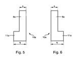
- the outer connecting conductor parts 10a the width s, the leg parts of which in a normal to the plane of extension of the connecting conductor part 10a extending direction, about half as much is the same as the corresponding width q of the crosspiece 11a of this connecting conductor part 10a.
- the width of the leg parts also for the inner connecting conductor parts 10b is approximately half the width of the crosspiece 11b.
- FIG. 10 to 18 are the connecting conductors U-shaped with leg parts connected to each other by a cross piece 11 c educated.
- Form the partial regions 8a, 8b which are movable relative to one another the leg parts and are at their ends removed from the crosspiece 11 c connected in one piece by a bridge region 12, which acts as a deformation point is trained.
- Fig. 11 it can be seen that the bridge areas 12 each proceeding from the partial area 8a to the partial area 8b have a wavy course deviating from a straight line.
- the bridge area has an embossing in the direction of the groove width a resilient movement of the two sections running in the direction of the groove depth 8a, 8b and the somewhat when assembling the secondary part protrude beyond the air gap surface of the laminated core and into the straight Extension of the air gap can protrude. That from the end of the inner partial region 8b distant from the bridge region 12 is rigid with the crossbar 11 c connected. By deforming the bridge area 12 the outer portions 8a towards the crossbar 11c and movable away from it.
- the end regions of the partial regions 8a, 8b that are removed from the bridge region 12 have connection points for positive connection or caulking of the free end of the partial area 8a with the opposite end area of partial area 8b, which is marked in FIG. 16 by a dotted circle are.
- the free end area of the partial area 8a is approximately hook-shaped and engages behind a projection of the opposite in the use position End area of sub-area 8b. 11 and 16 it can be seen that the between these end regions formed slot 9 has a component that runs obliquely to the longitudinal direction of the crosspiece 11 c.
- the connecting conductor 5 is on an end region in one piece with a grooved rod 4 to an approximately L-shaped Molded conductor connected.
- the partial areas 8a, 8b are the one formed between them Recording 7 provided for a slot rod end 6 of a further molded conductor.
- the molded part conductors are U-shaped and each have two slot bars 4 running parallel to one another on, which are integrally connected to one another via a connecting conductor 5 '.
- the kit has two types of molded conductors, the slot bars 4 of which are different are long. It can be clearly seen that the connecting conductors 5, 5 'are connected the ends of the soft magnetic core in two in each Direction of extension of the slot bars 4 arranged mutually offset layers are.
- the assembly is carried out and then welding the inner connecting conductors 5 onto the slot bar ends 6 of the short slot bars 4. Then a thin insulating washer is also on this side hung up and then the outer connecting conductors and a Star point conductor part 13 added.
- the thin insulating washers between the winding head halves and between the End faces of the soft magnetic core 2 and the inner end winding layers preferably consist of an impregnable layer material and serve primarily as a spacer.
- the insulation strength is due to the impregnation ensured with an insulating resin advantageous for negative and / or positive pressure.
- a complete filling of all cavities and gaps in the winding heads is guaranteed the insulation of the conductor parts also in the circumferential direction of the soft magnetic Core 2.
- the rod winding is also made of L-shaped Molded ladders can be joined (Fig. 18).
- Each L-shaped molded ladder consists of a grooved rod 4 and a connecting conductor 5, the Manufactured both in one piece with a subsequent insulation step as well can be done by joining two separately manufactured parts.
- the Inserting the L-shaped conductor into the soft magnetic core 2 will be the exact one Position of the L-shaped conductor is ensured by the guide in the grooves 3. Damage to the insulation is avoided using a threading template.
- the Insulation resistance measured. There is no low-resistance contact between the phases and the soft magnetic core 2, the soft magnetic Core 2 assembled rod winding with a temperature stable Insulating resin preferably impregnated with the rod winding heated under vacuum.
- the L-shaped part conductor also advantageously in one piece in a follow-on tool made of low-oxygen Copper sheets are prefabricated.
- This is preferably a Profile wire once at the later transition point slot-winding head over the high one Edge bent and then the area later in the winding head embossed several times and bent over the narrow edge.
- the preformed winding head area of the L-shaped component conductor is thermoformed and / or forging into its final shape.
- Such L-shaped part conductors for the inner end winding layers form a receptacle for the molded part end to be attached with which this molded part end embrace on the air gap side.
- the two radially extending sections 8a, 8b right and left of the receptacle 7 for the end of the slot bar due to the below the slot 9 provided slot movable relative to each other.
Landscapes
- Engineering & Computer Science (AREA)
- Power Engineering (AREA)
- Manufacture Of Motors, Generators (AREA)
- Emergency Protection Circuit Devices (AREA)
- Multi-Process Working Machines And Systems (AREA)
- Control Of Electric Motors In General (AREA)
- Insulation, Fastening Of Motor, Generator Windings (AREA)
- Transformers For Measuring Instruments (AREA)
Abstract
Description
- Fig. 1
- einen Teilquerschnitt durch den Wickelkopf einer teilweise montierten elektrischen Rotations-Maschine in abgewickelter Darstellung, wobei die Querschnittsebene rechtwinklig zur Rotationsachse der Maschine durch Verbindungsleiter verläuft, die Nutstabenden miteinander verbinden,
- Fig. 2
- eine Ansicht auf die in Gebrauchsstellung einem Sekundärteil der elektrischen Maschine abgewandte Seite eines ersten Ausführungsbeispiels eines Verbindungsleiters,
- Fig. 3
- eine Aufsicht auf die in Gebrauchsstellung einem weichmagnetischen Kern der elektrischen Maschine zugewandte Seite des in Fig. 2 gezeigten Verbindungsleiters,
- Fig. 4
- eine Ansicht auf die in Gebrauchsstellung einem Sekundärteil zugewandte Seite des in Fig. 2 und 3 gezeigten Verbindungsleiters,
- Fig. 5 und 6
- Seitenansichten des in den Fig. 2 bis 4 und 7 bis 9 gezeigten Verbindungsleiters,
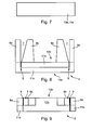
- Fig. 7
- eine Ansicht auf die in Gebrauchsstellung dem Sekundärteil abgewandte Seite eines zweiten Ausführungsbeispiels eines Verbindungsleiters,
- Fig. 8
- eine Aufsicht auf die in Gebrauchsstellung dem weichmagnetischen Kern abgewandte Seite des in Fig. 7 gezeigten Verbindungsleiters,
- Fig. 9
- eine Ansicht auf die in Gebrauchsstellung dem Sekundärteil zugewandte Seite des in Fig. 7 und 8 gezeigten Verbindungsleiters,
- Fig. 10
- eine Ansicht auf die in Gebrauchsstellung dem Sekundärteil abgewandte Seite eines dritten Ausführungsbeispiels eines Verbindungsleiters,
- Fig. 11
- eine Ansicht auf die in Gebrauchsstellung dem weichmagnetischen Kern abgewandte Seite des in Fig. 10 gezeigten Verbindungsleiters,
- Fig. 12
- eine Ansicht auf die in Gebrauchsstellung dem Sekundärteil zugewandte Seite des in Fig. 10 und 11 gezeigten Verbindungsleiters,
- Fig. 13 und 14
- Seitenansichten der in den Fig. 10 bis 12 gezeigten Verbindungsleiter,
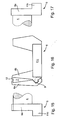
- Fig. 15 und 17
- Seitenansichten eines einstückig mit einem Nutstab verbundenen Verbindungsleiters, wobei der Nutstab nur teilweise dargestellt ist,
- Fig. 18
- eine Aufsicht auf die in Montagestellung dem Sekundärteil zugewandte Seite den in Fig. 15 bis 17 gezeigten Formteilleiters und
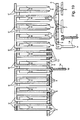
- Fig. 19
- eine Aufsicht auf die abgewickelte Stabwicklung, wobei rechts in der oberen Hälfte der Abbildung die Bauteile der Stabwicklung in Vormontagestellung und in der unteren Hälfte der Abbildung in Endmontagestellung dargestellt sind.
- Auf einer ersten Stirnseite des weichmagnetischen Kerns 2 wird eine innere Wickelkopfschicht mit einem ersten L-Formteilleitertyp, der die kürzesten Nutstäbe 4 aufweist, montiert.
- Auf der gegenüberliegenden zweiten Stirnseite des weichmagnetischen Kerns 2 wird eine innere Wickelkopfschicht mit einem zweiten L-Formteilleitertyp montiert.
- Die Verbindungen zwischen diesen beiden inneren Wickelkopfschichten werden an der zweiten Stirnseite des weichmagnetischen Kerns 2 geschweißt.
- Ein Isolierschichtteil wird auf die zweite Stirnseite montiert.
- Auf der zweiten Stirnseite wird eine äußere Wickelkopfschicht mit einem dritten L-Formteilleitertyp und einem Sternpunktleiterteil 13 montiert.
- An der ersten Stirnseite werden die Fügestellen in der inneren Wickelkopfschicht geschweißt.
- Ein Isolierschichtteil wird auf die erste Stirnseite montiert.
- Auf der ersten Stirnseite wird eine äußere Wickelkopfschicht mit einem vierten L-Formteilleitertyp, der die längsten Nutstäbe 4 aufweist, montiert.
- Die Fügestellen in der äußeren Wickelkopfschicht der ersten Stirnseite werden geschweißt.
- Gegebenenfalls werden drei Anschlussleiter 14 an die Wicklungsenden angefügt.
Claims (17)
- Bausatz zum Erstellen einer ein Primärteil (1) und ein relativ dazu bewegbares Sekundärteil aufweisenden elektrischen Maschine, mit einem Nuten (3) aufweisenden weichmagnetischen Kern (2) für das Primärteil, mit in die Nuten (3) einsetzbaren Nutstäben (4) für eine verteilte Stabwicklung, mit Verbindungsleitern (5, 5') zum Verbinden der in Montagesstellung an einer Stirnseite des weichmagnetischen Kerns (2) aus den Nuten (3) herausragen Enden (6) der Nutstäbe, wobei mindestens ein Verbindungsleiter (5) wenigstens zwei Teilbereiche (8a, 8b) hat, zwischen denen eine Aufnahme (7) für ein mit dem Verbindungsleiter (5) zu verbindendes Nutstabende (6) gebildet ist, wobei die Teilbereiche (8a, 8b) an der in Montagesstellung dem Sekundärteil abgewandten Seite der Aufnahme (7) durch einen sich bis zu der Aufnahme (7) erstreckenden Schlitz (9) voneinander getrennt sind, wobei der Schlitz (9) in Montagesstellung quer zu einer durch die Nuten (3) aufgespannten Ebene verläuft, und wobei die Spaltweite des Schlitzes (9) durch elastisches Verformen des Verbindungsleiters (5) zum Anpassen der Abmessungen der Aufnahme (7) an die Abmessungen des Nutstabendes (6) veränderbar ist.
- Bausatz nach Anspruch 1, dadurch gekennzeichnet, dass der mindestens eine Verbindungsleiter (5) wenigstens zwei U- oder klammerförmig ausgebildete Verbindungsleiterteile (10a, 10b) aufweist, deren Schenkelteile die Teilbereiche (8a, 8b) bilden, und dass die Schenkelteile eines inneren Verbindungsleiterteils (10b) in Montagesstellung zwischen den Schenkelteilen eines äußeren Verbindungsleiterteils (10a) angeordnet sind.
- Bausatz nach Anspruch 1 oder 2, dadurch gekennzeichnet, dass die Verbindungsleiterteile (5) Querstege (11a, 11b, 11c) aufweisen, welche die Schenkelteile miteinander verbinden, und dass die Verbindungsleiterteile (5) derart ausgebildet sind, dass die Querstege (11a, 11b, 11c) der äußeren und inneren Verbindungsleiterteile (10a, 10b) mindestens eines Verbindungsleiters (5) in Montagesstellung in Erstreckungsrichtung der Nuten (3) hintereinander angeordnet sind.
- Bausatz nach einem der Ansprüche 1 bis 3, dadurch gekennzeichnet, dass die inneren Verbindungsleiterteile (10a) jeweils über ihre gesamte Erstreckungsfläche quer zur Erstreckungsfläche eine etwa konstante Dicke aufweisen.
- Bausatz nach einem der Ansprüche 1 bis 4, dadurch gekennzeichnet, dass die Verbindungsleiterteile (10a, 10b) derart ausgebildet sind, dass der Quersteg (11 b) wenigstens eines inneren Verbindungsleiterteils (10b) in Montagesstellung dichter an dem weichmagnetischen Kern (2) angeordnet ist als der Quersteg (11a) wenigstens eines äußeren Verbindungsleiterteils (10a).
- Bausatz nach einem der Ansprüche 1 bis 5, dadurch gekennzeichnet, dass die Verbindungsleiterteile (10a, 10b) der einzelnen Verbindungsleiter (5) jeweils miteinander verbunden sind, vorzugsweise mittels einer Schnappverbindung.
- Bausatz nach einem der Ansprüche 1 bis 6, dadurch gekennzeichnet, dass die Verbindungsleiterteile (10a, 10b) derart ausgebildet sind, dass die Querstege (11a, 11b) der äußeren und inneren Verbindungsleiterteile (10a, 10b) mindestens eines Verbindungsleiters (5) in Monatagestellung in einer normal zu der durch die Nuten (3) aufgespannten Ebene verlaufenden Richtung hintereinander angeordnet sind.
- Bausatz nach einem der Ansprüche 1 bis 7, dadurch gekennzeichnet, dass bei wenigstens einem äußeren Verbindungsleiterteil (10a) die Breite (s), die dessen Schenkelteile in einer normal zur Erstreckungsebene des Verbindungsleiterteils (10a) verlaufenden Richtung aufweisen, etwa halb so groß ist wie die Breite (q), die der Quersteg (11a) dieses Verbindungsleiterteils (10a) in dieser Richtung hat.
- Bausatz nach einem der Ansprüche 1 bis 8, dadurch gekennzeichnet, dass der Quersteg (11a) des äußeren Verbindungsleiterteils (10a) und der Quersteg (11 b) des inneren Verbindungsleiters (10b) einstückig miteinander verbunden sind.
- Bausatz nach einem der Ansprüche 1 bis 9, dadurch gekennzeichnet, dass wenigstens ein Verbindungsleiter (5) an einem Endbereich vorzugsweise einstückig mit einem Nutstab (4) zu einem L-förmigen Formteilleiter verbunden ist, und dass an einem von diesem Endbereich entfernten weiteren Endbereich des Verbindungsleiters (5) die Teilbereiche (8a, 8b) mit der dazwischen gebildeten Aufnahme (7) für das Nutstabende (6) eines weiteren Formteilleiters vorgesehen sind.
- Bausatz nach einem der Ansprüche 1 bis 10, dadurch gekennzeichnet, dass er mehrere Arten von Formteilleitern mit unterschiedlich langen Nutstäben (4) aufweist, dass die Länge der Nutstäbe (4) derart auf die Abmessungen der Verbindungsleiter (5, 5') und des weichmagnetischen Kerns (2) abgestimmt ist, dass in Montagestellung an wenigstens einer Stirnseite des weichmagnetischen Kerns (2) die Verbindungsleiter in mehreren, in Erstreckungsrichtung der Nutstäbe (4) zueinander versetzten Lagen angeordnet sind, und dass die einzelnen Wicklungsstränge der Stabwicklung vorzugsweise baugleiche Formteilleiter aufweisen.
- Bausatz nach einem der Ansprüche 1 bis 11, dadurch gekennzeichnet, dass zusätzlich zu den die Teilbereiche (8a, 8b) aufweisenden ersten Verbindungsleitern (5) zweite Verbindungsleiter (5') vorgesehen sind, die jeweils zwei Nutstäbe (4) U-förmig und vorzugsweise einstückig miteinander verbinden, und dass die Verbindungsleiter (5, 5') derart ausgebildet sind, dass die ersten Verbindungsleiter (5) bei wenigstens einem Wicklungsstrang der Stabwicklung in Montagestellung jeweils an einer ersten Stirnseite des weichmagnetischen Kerns (2) und die zweiten Verbindungsleiter (5') jeweils an der dieser Stirnseite gegenüberliegenden zweiten Stirnseite des weichmagnetischen Kerns (2) angeordnet sind.
- Bausatz nach einem der Ansprüche 1 bis 12, dadurch gekennzeichnet, dass die Teilbereiche (8a, 8b) wenigstens einer Aufnahme an ihren in Montagestellung dem Sekundärteil zugewandten Enden durch einen wenigstens eine Biegeverformungsstelle aufweisenden Brückenbereich (12) einstückig miteinander verbunden sind.
- Bausatz nach einem der Ansprüche 1 bis 13, dadurch gekennzeichnet, dass der Brückenbereich (12), ausgehend von dem einen Teilbereich (8a) zu dem anderen Teilbereich (8b), einen von einer geraden Linie abweichenden, vorzugsweise wellenlinien- oder zickzackförmigen Verlauf aufweist.
- Bausatz nach einem der Ansprüche 1 bis 14, dadurch gekennzeichnet, dass die von dem Brückenbereich (12) entfernten Endbereiche der Teilbereiche (8a, 8b) Verbindungsstellen zum formschlüssigen Verbinden und insbesondere Verhaken und/oder Verstemmen der Teilbereiche (8a, 8b) aufweisen, und dass diese Verbindungsstellen vorzugsweise von der Aufnahme (7) für das Nutstabende (6) beabstandet sind.
- Bausatz nach einem der Ansprüche 1 bis 15, dadurch gekennzeichnet, dass der Schlitz (9) eine Komponente aufweist, die in einer in Montagestellung normal zur Erstreckungsrichtung der Nuten (3) verlaufenden Ebene schräg zur der durch die Nuten (3) aufgespannten Ebene verläuft.
- Bausatz nach einem der Ansprüche 1 bis 16, dadurch gekennzeichnet, dass sich der Querschnitt der Aufnahmen (7) und der Nutstabenden (6) in Montagestellung jeweils ausgehend von dem dem Sekundärteil zugewandten Ende der Aufnahme (7) zu dem gegenüberliegenden anderen Ende der Aufnahme (7) hin vorzugsweise V-förmig verjüngt.
Applications Claiming Priority (2)
| Application Number | Priority Date | Filing Date | Title |
|---|---|---|---|
| DE10326050 | 2003-06-10 | ||
| DE10326050 | 2003-06-10 |
Publications (3)
| Publication Number | Publication Date |
|---|---|
| EP1487086A2 true EP1487086A2 (de) | 2004-12-15 |
| EP1487086A3 EP1487086A3 (de) | 2005-07-20 |
| EP1487086B1 EP1487086B1 (de) | 2007-08-22 |
Family
ID=33185730
Family Applications (1)
| Application Number | Title | Priority Date | Filing Date |
|---|---|---|---|
| EP04013457A Expired - Lifetime EP1487086B1 (de) | 2003-06-10 | 2004-06-08 | Bausatz zum Erstellen einer elektrischen Maschine |
Country Status (3)
| Country | Link |
|---|---|
| EP (1) | EP1487086B1 (de) |
| AT (1) | ATE371292T1 (de) |
| DE (2) | DE102004027817A1 (de) |
Family Cites Families (4)
| Publication number | Priority date | Publication date | Assignee | Title |
|---|---|---|---|---|
| JPS5658749A (en) * | 1979-10-19 | 1981-05-21 | Toshiba Corp | Connection of stator winding for rotary electric machine |
| US4912831A (en) * | 1987-01-09 | 1990-04-03 | Westinghouse Electric Corp. | Method for assembling bolted stator coils |
| US6353198B1 (en) * | 2000-06-14 | 2002-03-05 | General Electric Company | Welded stator winding splice joint for rotary electric machines and method of forming the same |
| DE10033014A1 (de) * | 2000-07-06 | 2002-01-17 | Abb Alstom Power Nv | Statorwicklung für eine elektrische Maschine |
-
2004
- 2004-06-08 DE DE200410027817 patent/DE102004027817A1/de not_active Withdrawn
- 2004-06-08 DE DE502004004698T patent/DE502004004698D1/de not_active Expired - Lifetime
- 2004-06-08 AT AT04013457T patent/ATE371292T1/de not_active IP Right Cessation
- 2004-06-08 EP EP04013457A patent/EP1487086B1/de not_active Expired - Lifetime
Also Published As
| Publication number | Publication date |
|---|---|
| DE102004027817A1 (de) | 2004-12-30 |
| EP1487086A3 (de) | 2005-07-20 |
| EP1487086B1 (de) | 2007-08-22 |
| DE502004004698D1 (de) | 2007-10-04 |
| ATE371292T1 (de) | 2007-09-15 |
Similar Documents
| Publication | Publication Date | Title |
|---|---|---|
| DE4028420C2 (de) | ||
| EP2897254B1 (de) | Ringförmiges Lamellenpaket aus Einzelzahnpaketen sowie Verfahren zur Herstellung eines Lamellenpaketes | |
| DE68924566T2 (de) | Blechlamellen. | |
| WO2020120629A1 (de) | Stator, elektrische maschine und verfahren zur herstellung | |
| DE2444892C3 (de) | Verfahren zur Herstellung von streifenförmigen Anschlußelementen | |
| DE10161937A1 (de) | Drehstrommotor | |
| DE102021203954A1 (de) | Stator einer elektrischen Maschine | |
| WO2019223932A1 (de) | Stator einer elektrischen maschine und verfahren zur herstellung eines stators | |
| EP1372249A2 (de) | Transversalflussmaschine, insbesondere Unipolar-Transversalflussmaschine | |
| DE2314591C2 (de) | Verfahren zur Herstellung von lamellaren Leitern | |
| DE69607663T2 (de) | Baugruppe mit Gebläse und Wärmetauscher | |
| WO1995000997A1 (de) | Mehrphasige elektrische maschine mit einer wicklung aus flachen leiterformteilen | |
| DE102010033699B4 (de) | Schaltkopf für Elektromotoren und Verfahren zum Verbinden eines Schaltkopfes mit den Anschlusslitzen einer Elektromotorwicklung | |
| DE4206434C2 (de) | Miniaturmotor mit einem zusammengebauten Kommutator | |
| DE3505159C2 (de) | ||
| EP1487086B1 (de) | Bausatz zum Erstellen einer elektrischen Maschine | |
| EP3560076B1 (de) | Verfahren zum herstellen einer anordnung für eine steckspule einer elektrischen maschine und anordnung | |
| DE2340426C3 (de) | Gehäuse für einen Wechselstromkleinmotor aus zwei zusammensteckbaren Hälften | |
| DE4234175C2 (de) | Mehrphasige elektrische Maschine mit schleifenlos montierten Leitersträngen | |
| DE4236086C1 (de) | Elektrischer Widerstand und Verfahren zur Herstellung eines solchen Widerstands | |
| EP1338076B1 (de) | Stator für eine elektrische maschine und herstellungsverfahren dafür | |
| DE2604466B2 (de) | Elektrischer Schalter mit in Buchsen einlegbaren, feststehenden Kontaktelementen | |
| EP2814140A2 (de) | Bleche und Blechpaket für elektrische Maschinen | |
| DE102017100891A1 (de) | Motorständer und Verfahren zum Bilden des Motorständers | |
| DE69300971T2 (de) | Verfahren und Vorrichtung zur Herstellung eines Ankers. |
Legal Events
| Date | Code | Title | Description |
|---|---|---|---|
| PUAI | Public reference made under article 153(3) epc to a published international application that has entered the european phase |
Free format text: ORIGINAL CODE: 0009012 |
|
| AK | Designated contracting states |
Kind code of ref document: A2 Designated state(s): AT BE BG CH CY CZ DE DK EE ES FI FR GB GR HU IE IT LI LU MC NL PL PT RO SE SI SK TR |
|
| AX | Request for extension of the european patent |
Extension state: AL HR LT LV MK |
|
| PUAL | Search report despatched |
Free format text: ORIGINAL CODE: 0009013 |
|
| AK | Designated contracting states |
Kind code of ref document: A3 Designated state(s): AT BE BG CH CY CZ DE DK EE ES FI FR GB GR HU IE IT LI LU MC NL PL PT RO SE SI SK TR |
|
| AX | Request for extension of the european patent |
Extension state: AL HR LT LV MK |
|
| 17P | Request for examination filed |
Effective date: 20060120 |
|
| AKX | Designation fees paid |
Designated state(s): AT BE BG CH CY CZ DE DK EE ES FI FR GB GR HU IE IT LI LU MC NL PL PT RO SE SI SK TR |
|
| GRAP | Despatch of communication of intention to grant a patent |
Free format text: ORIGINAL CODE: EPIDOSNIGR1 |
|
| GRAS | Grant fee paid |
Free format text: ORIGINAL CODE: EPIDOSNIGR3 |
|
| GRAA | (expected) grant |
Free format text: ORIGINAL CODE: 0009210 |
|
| AK | Designated contracting states |
Kind code of ref document: B1 Designated state(s): AT BE BG CH CY CZ DE DK EE ES FI FR GB GR HU IE IT LI LU MC NL PL PT RO SE SI SK TR |
|
| REG | Reference to a national code |
Ref country code: GB Ref legal event code: FG4D Free format text: NOT ENGLISH |
|
| REG | Reference to a national code |
Ref country code: CH Ref legal event code: EP |
|
| REG | Reference to a national code |
Ref country code: IE Ref legal event code: FG4D Free format text: LANGUAGE OF EP DOCUMENT: GERMAN |
|
| REF | Corresponds to: |
Ref document number: 502004004698 Country of ref document: DE Date of ref document: 20071004 Kind code of ref document: P |
|
| ET | Fr: translation filed | ||
| PG25 | Lapsed in a contracting state [announced via postgrant information from national office to epo] |
Ref country code: BG Free format text: LAPSE BECAUSE OF FAILURE TO SUBMIT A TRANSLATION OF THE DESCRIPTION OR TO PAY THE FEE WITHIN THE PRESCRIBED TIME-LIMIT Effective date: 20071122 Ref country code: ES Free format text: LAPSE BECAUSE OF FAILURE TO SUBMIT A TRANSLATION OF THE DESCRIPTION OR TO PAY THE FEE WITHIN THE PRESCRIBED TIME-LIMIT Effective date: 20071203 Ref country code: NL Free format text: LAPSE BECAUSE OF FAILURE TO SUBMIT A TRANSLATION OF THE DESCRIPTION OR TO PAY THE FEE WITHIN THE PRESCRIBED TIME-LIMIT Effective date: 20070822 Ref country code: FI Free format text: LAPSE BECAUSE OF FAILURE TO SUBMIT A TRANSLATION OF THE DESCRIPTION OR TO PAY THE FEE WITHIN THE PRESCRIBED TIME-LIMIT Effective date: 20070822 |
|
| NLV1 | Nl: lapsed or annulled due to failure to fulfill the requirements of art. 29p and 29m of the patents act | ||
| PG25 | Lapsed in a contracting state [announced via postgrant information from national office to epo] |
Ref country code: PL Free format text: LAPSE BECAUSE OF FAILURE TO SUBMIT A TRANSLATION OF THE DESCRIPTION OR TO PAY THE FEE WITHIN THE PRESCRIBED TIME-LIMIT Effective date: 20070822 |
|
| GBV | Gb: ep patent (uk) treated as always having been void in accordance with gb section 77(7)/1977 [no translation filed] |
Effective date: 20070822 |
|
| REG | Reference to a national code |
Ref country code: IE Ref legal event code: FD4D |
|
| PG25 | Lapsed in a contracting state [announced via postgrant information from national office to epo] |
Ref country code: GR Free format text: LAPSE BECAUSE OF FAILURE TO SUBMIT A TRANSLATION OF THE DESCRIPTION OR TO PAY THE FEE WITHIN THE PRESCRIBED TIME-LIMIT Effective date: 20071123 Ref country code: DK Free format text: LAPSE BECAUSE OF FAILURE TO SUBMIT A TRANSLATION OF THE DESCRIPTION OR TO PAY THE FEE WITHIN THE PRESCRIBED TIME-LIMIT Effective date: 20070822 |
|
| PG25 | Lapsed in a contracting state [announced via postgrant information from national office to epo] |
Ref country code: PT Free format text: LAPSE BECAUSE OF FAILURE TO SUBMIT A TRANSLATION OF THE DESCRIPTION OR TO PAY THE FEE WITHIN THE PRESCRIBED TIME-LIMIT Effective date: 20080122 Ref country code: CZ Free format text: LAPSE BECAUSE OF FAILURE TO SUBMIT A TRANSLATION OF THE DESCRIPTION OR TO PAY THE FEE WITHIN THE PRESCRIBED TIME-LIMIT Effective date: 20070822 Ref country code: GB Free format text: LAPSE BECAUSE OF FAILURE TO SUBMIT A TRANSLATION OF THE DESCRIPTION OR TO PAY THE FEE WITHIN THE PRESCRIBED TIME-LIMIT Effective date: 20070822 Ref country code: IE Free format text: LAPSE BECAUSE OF FAILURE TO SUBMIT A TRANSLATION OF THE DESCRIPTION OR TO PAY THE FEE WITHIN THE PRESCRIBED TIME-LIMIT Effective date: 20070822 Ref country code: SK Free format text: LAPSE BECAUSE OF FAILURE TO SUBMIT A TRANSLATION OF THE DESCRIPTION OR TO PAY THE FEE WITHIN THE PRESCRIBED TIME-LIMIT Effective date: 20070822 |
|
| PLBE | No opposition filed within time limit |
Free format text: ORIGINAL CODE: 0009261 |
|
| STAA | Information on the status of an ep patent application or granted ep patent |
Free format text: STATUS: NO OPPOSITION FILED WITHIN TIME LIMIT |
|
| PG25 | Lapsed in a contracting state [announced via postgrant information from national office to epo] |
Ref country code: SE Free format text: LAPSE BECAUSE OF FAILURE TO SUBMIT A TRANSLATION OF THE DESCRIPTION OR TO PAY THE FEE WITHIN THE PRESCRIBED TIME-LIMIT Effective date: 20071122 Ref country code: RO Free format text: LAPSE BECAUSE OF FAILURE TO SUBMIT A TRANSLATION OF THE DESCRIPTION OR TO PAY THE FEE WITHIN THE PRESCRIBED TIME-LIMIT Effective date: 20070822 |
|
| 26N | No opposition filed |
Effective date: 20080526 |
|
| BERE | Be: lapsed |
Owner name: LUK LAMELLEN UND KUPPLUNGSBAU BETEILIGUNGS K.G. Effective date: 20080630 |
|
| PG25 | Lapsed in a contracting state [announced via postgrant information from national office to epo] |
Ref country code: MC Free format text: LAPSE BECAUSE OF NON-PAYMENT OF DUE FEES Effective date: 20080630 |
|
| REG | Reference to a national code |
Ref country code: CH Ref legal event code: PL |
|
| PG25 | Lapsed in a contracting state [announced via postgrant information from national office to epo] |
Ref country code: BE Free format text: LAPSE BECAUSE OF NON-PAYMENT OF DUE FEES Effective date: 20080630 |
|
| PG25 | Lapsed in a contracting state [announced via postgrant information from national office to epo] |
Ref country code: EE Free format text: LAPSE BECAUSE OF FAILURE TO SUBMIT A TRANSLATION OF THE DESCRIPTION OR TO PAY THE FEE WITHIN THE PRESCRIBED TIME-LIMIT Effective date: 20070822 |
|
| PG25 | Lapsed in a contracting state [announced via postgrant information from national office to epo] |
Ref country code: CH Free format text: LAPSE BECAUSE OF NON-PAYMENT OF DUE FEES Effective date: 20080630 Ref country code: SI Free format text: LAPSE BECAUSE OF FAILURE TO SUBMIT A TRANSLATION OF THE DESCRIPTION OR TO PAY THE FEE WITHIN THE PRESCRIBED TIME-LIMIT Effective date: 20070822 Ref country code: LI Free format text: LAPSE BECAUSE OF NON-PAYMENT OF DUE FEES Effective date: 20080630 |
|
| PG25 | Lapsed in a contracting state [announced via postgrant information from national office to epo] |
Ref country code: CY Free format text: LAPSE BECAUSE OF FAILURE TO SUBMIT A TRANSLATION OF THE DESCRIPTION OR TO PAY THE FEE WITHIN THE PRESCRIBED TIME-LIMIT Effective date: 20070822 |
|
| PG25 | Lapsed in a contracting state [announced via postgrant information from national office to epo] |
Ref country code: AT Free format text: LAPSE BECAUSE OF NON-PAYMENT OF DUE FEES Effective date: 20080608 |
|
| PG25 | Lapsed in a contracting state [announced via postgrant information from national office to epo] |
Ref country code: LU Free format text: LAPSE BECAUSE OF NON-PAYMENT OF DUE FEES Effective date: 20080608 Ref country code: HU Free format text: LAPSE BECAUSE OF FAILURE TO SUBMIT A TRANSLATION OF THE DESCRIPTION OR TO PAY THE FEE WITHIN THE PRESCRIBED TIME-LIMIT Effective date: 20080223 |
|
| PG25 | Lapsed in a contracting state [announced via postgrant information from national office to epo] |
Ref country code: TR Free format text: LAPSE BECAUSE OF FAILURE TO SUBMIT A TRANSLATION OF THE DESCRIPTION OR TO PAY THE FEE WITHIN THE PRESCRIBED TIME-LIMIT Effective date: 20070822 |
|
| PG25 | Lapsed in a contracting state [announced via postgrant information from national office to epo] |
Ref country code: IT Free format text: LAPSE BECAUSE OF NON-PAYMENT OF DUE FEES Effective date: 20080630 |
|
| REG | Reference to a national code |
Ref country code: DE Ref legal event code: R081 Ref document number: 502004004698 Country of ref document: DE Owner name: SCHAEFFLER TECHNOLOGIES AG & CO. KG, DE Free format text: FORMER OWNER: SCHAEFFLER TECHNOLOGIES GMBH & CO. KG, 91074 HERZOGENAURACH, DE Effective date: 20120828 Ref country code: DE Ref legal event code: R081 Ref document number: 502004004698 Country of ref document: DE Owner name: SCHAEFFLER TECHNOLOGIES GMBH & CO. KG, DE Free format text: FORMER OWNER: SCHAEFFLER TECHNOLOGIES GMBH & CO. KG, 91074 HERZOGENAURACH, DE Effective date: 20120828 |
|
| REG | Reference to a national code |
Ref country code: FR Ref legal event code: TP Owner name: SCHAEFFLER TECHNOLOGIES AG & CO. KG, DE Effective date: 20130408 |
|
| REG | Reference to a national code |
Ref country code: DE Ref legal event code: R081 Ref document number: 502004004698 Country of ref document: DE Owner name: SCHAEFFLER TECHNOLOGIES AG & CO. KG, DE Free format text: FORMER OWNER: SCHAEFFLER TECHNOLOGIES AG & CO. KG, 91074 HERZOGENAURACH, DE Effective date: 20140217 Ref country code: DE Ref legal event code: R081 Ref document number: 502004004698 Country of ref document: DE Owner name: SCHAEFFLER TECHNOLOGIES GMBH & CO. KG, DE Free format text: FORMER OWNER: SCHAEFFLER TECHNOLOGIES AG & CO. KG, 91074 HERZOGENAURACH, DE Effective date: 20140217 |
|
| REG | Reference to a national code |
Ref country code: DE Ref legal event code: R081 Ref document number: 502004004698 Country of ref document: DE Owner name: SCHAEFFLER TECHNOLOGIES AG & CO. KG, DE Free format text: FORMER OWNER: SCHAEFFLER TECHNOLOGIES GMBH & CO. KG, 91074 HERZOGENAURACH, DE Effective date: 20150211 |
|
| REG | Reference to a national code |
Ref country code: FR Ref legal event code: PLFP Year of fee payment: 12 |
|
| PGFP | Annual fee paid to national office [announced via postgrant information from national office to epo] |
Ref country code: FR Payment date: 20150630 Year of fee payment: 12 |
|
| PGFP | Annual fee paid to national office [announced via postgrant information from national office to epo] |
Ref country code: DE Payment date: 20150831 Year of fee payment: 12 |
|
| REG | Reference to a national code |
Ref country code: DE Ref legal event code: R119 Ref document number: 502004004698 Country of ref document: DE |
|
| REG | Reference to a national code |
Ref country code: FR Ref legal event code: ST Effective date: 20170228 |
|
| PG25 | Lapsed in a contracting state [announced via postgrant information from national office to epo] |
Ref country code: DE Free format text: LAPSE BECAUSE OF NON-PAYMENT OF DUE FEES Effective date: 20170103 Ref country code: FR Free format text: LAPSE BECAUSE OF NON-PAYMENT OF DUE FEES Effective date: 20160630 |
|
| P01 | Opt-out of the competence of the unified patent court (upc) registered |
Effective date: 20230519 |