EP1487083A2 - Elektromotoranordnung - Google Patents
Elektromotoranordnung Download PDFInfo
- Publication number
- EP1487083A2 EP1487083A2 EP04102057A EP04102057A EP1487083A2 EP 1487083 A2 EP1487083 A2 EP 1487083A2 EP 04102057 A EP04102057 A EP 04102057A EP 04102057 A EP04102057 A EP 04102057A EP 1487083 A2 EP1487083 A2 EP 1487083A2
- Authority
- EP
- European Patent Office
- Prior art keywords
- bearing holder
- holes
- recording apparatus
- magnetic reading
- receiving respective
- Prior art date
- Legal status (The legal status is an assumption and is not a legal conclusion. Google has not performed a legal analysis and makes no representation as to the accuracy of the status listed.)
- Withdrawn
Links
Images


Classifications
-
- G—PHYSICS
- G11—INFORMATION STORAGE
- G11B—INFORMATION STORAGE BASED ON RELATIVE MOVEMENT BETWEEN RECORD CARRIER AND TRANSDUCER
- G11B15/00—Driving, starting or stopping record carriers of filamentary or web form; Driving both such record carriers and heads; Guiding such record carriers or containers therefor; Control thereof; Control of operating function
- G11B15/18—Driving; Starting; Stopping; Arrangements for control or regulation thereof
- G11B15/26—Driving record carriers by members acting directly or indirectly thereon
- G11B15/28—Driving record carriers by members acting directly or indirectly thereon through rollers driving by frictional contact with the record carrier, e.g. capstan; Multiple arrangements of capstans or drums coupled to means for controlling the speed of the drive; Multiple capstan systems alternately engageable with record carrier to provide reversal
-
- H—ELECTRICITY
- H02—GENERATION; CONVERSION OR DISTRIBUTION OF ELECTRIC POWER
- H02K—DYNAMO-ELECTRIC MACHINES
- H02K1/00—Details of the magnetic circuit
- H02K1/06—Details of the magnetic circuit characterised by the shape, form or construction
- H02K1/22—Rotating parts of the magnetic circuit
- H02K1/27—Rotor cores with permanent magnets
- H02K1/2786—Outer rotors
- H02K1/2787—Outer rotors the magnetisation axis of the magnets being perpendicular to the rotor axis
- H02K1/2789—Outer rotors the magnetisation axis of the magnets being perpendicular to the rotor axis the rotor consisting of two or more circumferentially positioned magnets
- H02K1/2791—Surface mounted magnets; Inset magnets
-
- H—ELECTRICITY
- H02—GENERATION; CONVERSION OR DISTRIBUTION OF ELECTRIC POWER
- H02K—DYNAMO-ELECTRIC MACHINES
- H02K1/00—Details of the magnetic circuit
- H02K1/06—Details of the magnetic circuit characterised by the shape, form or construction
- H02K1/12—Stationary parts of the magnetic circuit
- H02K1/18—Means for mounting or fastening magnetic stationary parts on to, or to, the stator structures
- H02K1/187—Means for mounting or fastening magnetic stationary parts on to, or to, the stator structures to inner stators
-
- H—ELECTRICITY
- H02—GENERATION; CONVERSION OR DISTRIBUTION OF ELECTRIC POWER
- H02K—DYNAMO-ELECTRIC MACHINES
- H02K11/00—Structural association of dynamo-electric machines with electric components or with devices for shielding, monitoring or protection
- H02K11/30—Structural association with control circuits or drive circuits
- H02K11/33—Drive circuits, e.g. power electronics
-
- H—ELECTRICITY
- H02—GENERATION; CONVERSION OR DISTRIBUTION OF ELECTRIC POWER
- H02K—DYNAMO-ELECTRIC MACHINES
- H02K5/00—Casings; Enclosures; Supports
- H02K5/04—Casings or enclosures characterised by the shape, form or construction thereof
- H02K5/16—Means for supporting bearings, e.g. insulating supports or means for fitting bearings in the bearing-shields
- H02K5/163—Means for supporting bearings, e.g. insulating supports or means for fitting bearings in the bearing-shields radially supporting the rotary shaft at only one end of the rotor
Definitions
- the present invention relates to a motor assembly comprising a central stator, i.e. a stator about which the rotor rotates, and a PCB mounted to the stator.
- a typical use of a low-profile motor is for driving the capstan of a a magnetric recording/reproducing apparatus such as a VCR or a camcorder.
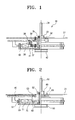
- Figure 1 shows an example of a capstan motor assembly.
- the capstan motor assembly 30 has a plate 31 and a PCB 32 below the plate 31.
- a bearing holder 33 is fixed to the plate 31 by means of a screw.
- a shaft 33 is supported coaxially within the bearing holder 33 by bearings 35.
- the cores 37 of a stator radiate from the bearing holder 33.
- a coil 36 is fixed to each core by a screw.
- a stator core 37 is connected by a holder pin 38 to the PCB 32 which fixes the reletive positions of the PCB 32, the bearing holder 33 and the plate 31.
- the lower end of the holder pin 38 is fitted into a hole, formed in a stator core 37, and the upper end of the holder pin 38 is fitted into a hole, formed in the PCB 32.
- a lead 39 is disposed near the holder pin 38 and extends between the PCB 32 and the stator core 7. The lead 39 is an extension of the coil 36 on the stator core 37 and is soldered to the PCB 32.
- a rotor 41 and a pulley 42 are fixed to the lower end of the shaft.
- the rotor 41 has a circumferential wall, the inside of which is lined with a ring of permenant magnets 43.
- a motor assembly is characterised in that the PCB is fastened to the stator by an integral rivet projecting from the stator. Consequently, there is a reduction in the number of components from the number that would otherwise be required.
- the PCB is fastened to the stator by a plurality of integral rivets projecting from the stator.
- the stator may comprises a central bearing housing and a ring from which a plurality of salient poles project radially outwards.
- the ring is fastened to the bearing housing by one of more integral rivets projecting from the bearing housing.
- the or each integral rivet projects parallel to the axis of rotation of the motor's rotor.
- the or each integral rivet is formed of a plastics material.
- a method of manufacturing an assembly according to the present invention comprises using heat for deforming the distal end of each PCB-fastening rivet such that it spreads and prevents removal of the PCB or the ring.
- a motor assembly according to the present invention may conveniently be employed in a tape recorder/player, e.g. a VCR or a camcorder, to drive its capstan.
- a tape recorder/player e.g. a VCR or a camcorder
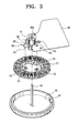
- a capstan motor assembly for a magnetic recording/reading apparatus comprises a bearing holder 60 which rotatably supports a shaft 50, a stator core 70 coupled to the bearing holder 60, a PCB 80 coupled to the bearing holder 60 and a rotor 90 coupled to the lower end of the shaft 50.
- the shaft 50 is supported by means of a bearing 52 so as to be rotatable with respect to the bearing holder 60.
- the bearing holder 60 is fixed to a plate 31, disposed to be apart from an upper side of a deck of the magnetic recording/reading apparatus.
- the bearing holder 60 is fixed to the plate 31 by a screw S.
- a threaded holes 61 is provided in an upper portion of the bearing holder 60 for receiving the screw S.
- a plurality of these threaded holes 61 are formed equidistantly around a shaft coupling portion 60a, in which the shaft 50 is located.
- three threaded holes 61 are provided by way of example.
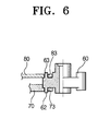
- the stator is coupled to a lower portion of the bearing holder 60. Coils 71 are wound on cores 70 of the stator. As shown in Figure 3, the stator is provided with a plurality of fixing holes 73 at desired positions to facilitate coupling to the bearing holder 60. A plurality of tags 74 are integrally formed with the stator so as to extend radially inwards. Each of the fixing holes 73 is formed in a corresponding tab 74. The fixing holes 73 are symmetrically formed at desired anglular spacings with the shaft coupling portion 60a in the center.
- the PCB 80 is supported by the bearing holder 60 so as to be positioned underneath the plate 31.
- a coil lead is connected to the PCB 80 by means of soldering or other conventional electrical connection.
- the PCB 80 is coupled to the upper portion of the bearing holder 60 in the same way as the stator. To this end, the PCB 80 has a fixing hole 83. It is preferred to provide multiple fixing holes 83.
- the rotor 90 is coupled to the lower end of the shaft 50 for rotation with the shaft 50.
- the rotor 90 has a circumferential wall and magnets 91 are disposed around the inside of the circumferential wall.
- a pulley 93 is coupled to the rotor 90 so as to be rotated together with the rotor 90. Driving for a tape reel of a tape cassette in the magnetic recording/reading apparatus taken the pulley 93.
- the bearing holder 60 has fixing bosses 62, 63 which are melted to the stator core 70 and the PCB 80.
- the stator core 70 and the PCB 80 are each melted to the bearing holder 60 in a plurality of locations.
- the fixing boss is divided into a lower fixing boss 62 protruding downwards and an upper fixing boss 63 protruding upwards.
- the lower fixing boss 62 is fitted into the fixing hole 73 and melted by a suitable machine so that it spreads slightly over the lower surface of the stator. Therefore, the stator can be fixed without any separate coupling members, such as screws or rivets, etc.
- the upper fixing boss 63 is fitted into the fixing hole 83 in the PCB 80 and melted to the upper surface of the PCB 80, such that the PCB 80 is in close contact with the bearing holder 60.
- the PCB 80 is also fixed to the bearing holder 60 in a simple way without any separate coupling member.
- only two fixing holes 83 are provided at the PCB 80. Therefore, two out of the three upper fixing bosses 63 are used.
- the lower and upper fixing bosses 62, 63 are aligned with each other so that an upper fixing boss 63 is axially aligned with a lower fixing boss 62.
- the plurality of lower and upper fixing bosses 62, 63 are provided so as protrude downwards and upwards from the bearing holder 60.
- the fixing bosses 62, 63 are located so as to alternate with the threaded holes 61 and be equidistant (120°) around the shaft coupling portion 60a.
- Each of the fixing bosses 62, 63 and the threaded holes 61 are integrally formed in ribs 65 formed around the shaft coupling portion 60a.
- the heights of the fixing bosses 62, 63 are greater than the depths of the fixing holes 73, 83. Therefore, after the fixing bosses 62, 63 have been inserted into the fixing holes 73, 83, they project from the other ends of the holes 73, 83, thereby increasing the strengths of the joints. Accordingly, after the fixing bosses 62, 63 have been melted, as shown in Figure 2, the material covers each of the fixing holes 73, 83.
- the bearing holder 60 as described above is made of a plastic synthetic material which can be deformed by external heat and also rapidly cooled.
- the PCB and the stator core can be fixed to the bearing holder by the melting process. Therefore, since separate coupling members are not needed, the number of components is decreased and also a construction is simplified.
Landscapes
- Engineering & Computer Science (AREA)
- Power Engineering (AREA)
- Microelectronics & Electronic Packaging (AREA)
- Permanent Magnet Type Synchronous Machine (AREA)
- Motor Or Generator Frames (AREA)
- Brushless Motors (AREA)
- Manufacture Of Motors, Generators (AREA)
Applications Claiming Priority (2)
| Application Number | Priority Date | Filing Date | Title |
|---|---|---|---|
| KR2003036913 | 2003-06-09 | ||
| KR1020030036913A KR20040105882A (ko) | 2003-06-09 | 2003-06-09 | 자기 기록/재생장치의 캡스턴모터 조립체 |
Publications (2)
| Publication Number | Publication Date |
|---|---|
| EP1487083A2 true EP1487083A2 (de) | 2004-12-15 |
| EP1487083A3 EP1487083A3 (de) | 2007-03-07 |
Family
ID=33297382
Family Applications (1)
| Application Number | Title | Priority Date | Filing Date |
|---|---|---|---|
| EP04102057A Withdrawn EP1487083A3 (de) | 2003-06-09 | 2004-05-12 | Elektromotoranordnung |
Country Status (5)
| Country | Link |
|---|---|
| US (1) | US6911755B2 (de) |
| EP (1) | EP1487083A3 (de) |
| JP (1) | JP2005006491A (de) |
| KR (1) | KR20040105882A (de) |
| CN (1) | CN1573934A (de) |
Families Citing this family (4)
| Publication number | Priority date | Publication date | Assignee | Title |
|---|---|---|---|---|
| KR101070042B1 (ko) * | 2009-12-28 | 2011-10-04 | 삼성전기주식회사 | 모터 장치 및 상기 모터 장치를 제조하는 제조 방법 |
| KR101380223B1 (ko) * | 2011-09-30 | 2014-04-02 | 주식회사 모아텍 | 모터의 피씨비 및 플레이트 취부 구조 |
| JP2016226178A (ja) * | 2015-05-29 | 2016-12-28 | 日本電産株式会社 | モータ |
| CN108233586A (zh) * | 2016-12-22 | 2018-06-29 | 日本电产(东莞)有限公司 | 马达 |
Family Cites Families (8)
| Publication number | Priority date | Publication date | Assignee | Title |
|---|---|---|---|---|
| JP2668636B2 (ja) * | 1993-06-29 | 1997-10-27 | 株式会社三協精機製作所 | モータ |
| JPH1198770A (ja) * | 1997-09-19 | 1999-04-09 | Victor Co Of Japan Ltd | モータのステータ構造及びモータのステータ組立方法 |
| US5973428A (en) * | 1998-07-20 | 1999-10-26 | Nmb U.S.A. Inc. | Stator mounting method and apparatus for a motor |
| US6144135A (en) * | 1998-11-12 | 2000-11-07 | Ho; Jsewen | Stator structure for a direct-current fan motor |
| US6225716B1 (en) * | 1998-12-15 | 2001-05-01 | Honeywell International Inc | Commutator assembly apparatus for hall sensor devices |
| KR100377611B1 (ko) * | 1999-03-17 | 2003-03-26 | 가부시기가이샤 산교세이기 세이사꾸쇼 | 소형모터 |
| JP2001045727A (ja) * | 1999-07-28 | 2001-02-16 | Alps Electric Co Ltd | モータ装置 |
| US6703738B2 (en) * | 2000-11-29 | 2004-03-09 | Kokusan Denki Co., Ltd. | Outer rotor type brushless motor |
-
2003
- 2003-06-09 KR KR1020030036913A patent/KR20040105882A/ko not_active Ceased
-
2004
- 2004-02-18 US US10/779,709 patent/US6911755B2/en not_active Expired - Fee Related
- 2004-03-30 JP JP2004100193A patent/JP2005006491A/ja active Pending
- 2004-05-10 CN CNA2004100433517A patent/CN1573934A/zh active Pending
- 2004-05-12 EP EP04102057A patent/EP1487083A3/de not_active Withdrawn
Also Published As
| Publication number | Publication date |
|---|---|
| CN1573934A (zh) | 2005-02-02 |
| EP1487083A3 (de) | 2007-03-07 |
| JP2005006491A (ja) | 2005-01-06 |
| US6911755B2 (en) | 2005-06-28 |
| US20040245874A1 (en) | 2004-12-09 |
| KR20040105882A (ko) | 2004-12-17 |
Similar Documents
| Publication | Publication Date | Title |
|---|---|---|
| EP0776544B1 (de) | Motor mit eingegossenem spulenträger | |
| KR0132424B1 (ko) | 낮은 코깅 토오크를 갖는 디스크 드라이브 스핀들 모터 | |
| US7876008B2 (en) | Fan and motor having multiple insulators with an axially protruding conductor pin | |
| US5747908A (en) | Motor including an apparatus for mounting a rotor and stator coil to a printed circuit board | |
| KR101020799B1 (ko) | 스핀들 모터와 인쇄회로기판의 연결구조 | |
| EP0558181A1 (de) | IC-gesteuerter Gleichstrommotor | |
| US20110081258A1 (en) | Fan and motor having multiple insulators with an axially protruding conductor pin | |
| EP0803963A1 (de) | Zweiphasiger, einpoliger, kommutatorloser Gleichstrommotor | |
| US5572384A (en) | Magnetic disk drive device having lead wire holding structure | |
| US6215210B1 (en) | Motor, structure of stator of the motor and assembly method of the stator | |
| JP2009148103A (ja) | モータ及び冷却ファン | |
| US5268604A (en) | Armature of a small motor employing an insulating holder having a plurality of sections | |
| EP1487083A2 (de) | Elektromotoranordnung | |
| US5023734A (en) | Cylindrical rotary transducer | |
| JP2011167024A (ja) | Dcブラシレスモータ | |
| JP3425993B2 (ja) | モータ及び電磁石 | |
| JP2964110B2 (ja) | フラットモータのステータ構造 | |
| JP3397052B2 (ja) | スピンドルモータ | |
| JP2551167Y2 (ja) | ディスク駆動用モータ | |
| US6028747A (en) | Head drum assembly having a member locating and fixing video heads on an upper drum | |
| JP2551168Y2 (ja) | ディスク駆動用モータ | |
| JP2003324884A (ja) | モータ | |
| GB2201843A (en) | Magnetically biased bearing for an electric motor | |
| GB2209438A (en) | Brush gear for an electric motor | |
| JPH0511779U (ja) | ブラシレスモータのステータ構造 |
Legal Events
| Date | Code | Title | Description |
|---|---|---|---|
| PUAI | Public reference made under article 153(3) epc to a published international application that has entered the european phase |
Free format text: ORIGINAL CODE: 0009012 |
|
| AK | Designated contracting states |
Kind code of ref document: A2 Designated state(s): AT BE BG CH CY CZ DE DK EE ES FI FR GB GR HU IE IT LI LU MC NL PL PT RO SE SI SK TR |
|
| AX | Request for extension of the european patent |
Extension state: AL HR LT LV MK |
|
| PUAL | Search report despatched |
Free format text: ORIGINAL CODE: 0009013 |
|
| AK | Designated contracting states |
Kind code of ref document: A3 Designated state(s): AT BE BG CH CY CZ DE DK EE ES FI FR GB GR HU IE IT LI LU MC NL PL PT RO SE SI SK TR |
|
| AX | Request for extension of the european patent |
Extension state: AL HR LT LV MK |
|
| STAA | Information on the status of an ep patent application or granted ep patent |
Free format text: STATUS: THE APPLICATION IS DEEMED TO BE WITHDRAWN |
|
| 18D | Application deemed to be withdrawn |
Effective date: 20061201 |