EP1486810B1 - High-stability optical microscope - Google Patents
High-stability optical microscope Download PDFInfo
- Publication number
- EP1486810B1 EP1486810B1 EP02772834A EP02772834A EP1486810B1 EP 1486810 B1 EP1486810 B1 EP 1486810B1 EP 02772834 A EP02772834 A EP 02772834A EP 02772834 A EP02772834 A EP 02772834A EP 1486810 B1 EP1486810 B1 EP 1486810B1
- Authority
- EP
- European Patent Office
- Prior art keywords
- optical
- imaging
- photometric
- microscope
- optical microscope
- Prior art date
- Legal status (The legal status is an assumption and is not a legal conclusion. Google has not performed a legal analysis and makes no representation as to the accuracy of the status listed.)
- Expired - Fee Related
Links
Images
Classifications
-
- G—PHYSICS
- G02—OPTICS
- G02B—OPTICAL ELEMENTS, SYSTEMS OR APPARATUS
- G02B21/00—Microscopes
- G02B21/24—Base structure
-
- G—PHYSICS
- G02—OPTICS
- G02B—OPTICAL ELEMENTS, SYSTEMS OR APPARATUS
- G02B21/00—Microscopes
- G02B21/36—Microscopes arranged for photographic purposes or projection purposes or digital imaging or video purposes including associated control and data processing arrangements
- G02B21/362—Mechanical details, e.g. mountings for the camera or image sensor, housings
Definitions
- This invention relates to image recording and measuring for an extended time using optical equipment, optical measuring instruments or optical microscopes.
- an optical microscope in particular, is used to record images or measurements for an extended time, the microscope is displaced minutely such that the object point (object) is shifted or defocused (so-called drift).
- This invention provides a structure for a highly stable optical microscope that is suitable for stable image recording or measuring for several hours with an accuracy in the order of nanometers by preventing drift.
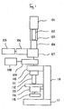
- Fig. 1 Conventional optical microscopes may be compared to a willow tree.
- the sample positioning stage, illumination system, optical observation system and other components mounted on the main stand lack balance and are asymmetrical about the optical axis in both mass and shape.
- Such an unstable structure is shown in Fig. 1 .
- 101 is a TV camera, 102 relay lens, 103 connecting tube, 104 straight tube, 105 eyepiece, 106 binocular tube 107 lens mount, 108 light source for fluorescence excitation 109 incident-light fluorescence equipment, 110 arm, 111 revolver, 112 objective lens, 113 stage, 114, vertical adjustment mechanism, 115 condenser, 116 main stand, and 117 base and illumination system.
- a conventional optical microscope as shown in Fig. 1 comprises a base and a illumination system at the bottom, with one end installed on the main stand.
- An arm is supported on the side of the upper end of the main stand, basically forming a U-shaped structure.
- the main stand supports the vertical adjustment mechanism for the sample mounting stage
- a condenser is set under the stage to guide illumination light from the illumination system to the sample being observed.
- the objective lens with a revolver to choose the lens magnification is mounted under the arm.
- the incident-light fluorescence equipment, lens mount, straight tube, relay lens, and TV camera are installed above the arm.
- the light source for fluorescence excitation is attached to the side of the incident-light fluorescence device.
- the binocular tube and eyepiece are mounted on the side of the lens mount.
- the accessory measuring units, cameras, and other devices are mounted like "branches and leaves” on a tree.
- the important components of an optical photometric system and optical imaging system, corresponding to the trunk of the tree, are unstable because the main stand is set on one end of the base and the illumination system.
- This cantilever structure makes not only the "branches and leaves” but also the thin "trunks” to sway like a willow tree.
- a half-mirror (including dichroic mirror) is typically installed on the inlet of the illumination system (incident-light fluorescence, total internal reflection fluorescence, transmitted light fluorescence, incident polarized light transmitted polarized light, bright field incidence, optical tweezers, etc.) and also on the inlet of the optical monitor system.
- a single imaging lens is, however, commonly used to reduce cost.
- the support fixtures for the illumination system are integrated with the optical imaging and photometric systems, with the result that instability caused by asymmetry in the shape and mass of the support fixtures for the illumination and monitor systems and shrinkage/elongation of those support fixtures due to temperature dependency bring about the fluctuation of the optical axis in the optical imaging and photometric systems.
- WO 00/03283 discloses a microscope and a method of obtaining images that includes a combination of a darkfield illuminations technique with electronic image inversion (converting a positive to a negative image) and other improvements to further enhance the contrast and resolution of the final image.
- US 5764409 discloses a portable emission microscope for analyzing failures in an integrated circuit chip while the chip is contained within a wafer sorter.
- a base for the microscope is placed over an opening in the wafer sorter.
- a translational apparatus is attached to the base for lowering a charge coupled device camera into an opening in the wafer sorter.
- a compact housing containing microscope optics is coupled to the camera.
- a flexible rubber boot is coupled to the microscope optics for shielding extraneous light from entering the camera.
- a vibration reducing apparatus is coupled to the microscope optics for preventing movement of the camera relative to the chip.
- the vibration reducing apparatus fits within the rubber boot and is a rigid, hollow cylinder having an adjustable length. The microscope optics view the chip through the cylinder.
- the cylinder is adjusted such that when the camera is lowered into position over the chip, the microscope optics are an appropriate distance from the chip, the cylinder presses against, and firmly contacts, the surface surrounding the chip, preventing movement of the camera relative to the chip, while the rubber boot resiliently conforms to the surface surrounding the chip.
- the present invention offers a highly stable optical microscope that is free from defocusing of samples and displacement (drift) of the object point (object) during observation.
- a dedicated, rather than common, imaging lens is mounted for each optical system headed by an imaging lens.
- the technical means adopted by a first aspect of this invention a highly stable optical microscope in which an objective lens, an imaging lens, a sample base, an optical imaging system and a photometric system are mounted without deviation on a straight guide mechanism, wherein said lenses and said systems form a straight line, and wherein support structures for supporting said lenses, said base and said systems are formed symmetrically about the optical axis in both and mass.
- a technical means adopted by a preferred embodiment is a structure of a highly stable optical microscope in which the support structure for the optical imaging system and photometric system are either a square truncated pyramid or circular truncated cone, to prevent changes in inclination caused by temperature fluctuations, vibration or other factors.
- Another technical means adopted by a preferred embodiment is a structure of a highly stable optical microscope in which, in an infinity corrected optical microscope, a half mirror (including dichroic mirror) and an imaging lens are combined and mounted at the inlet of an optical lighting system (incident-light fluorescence, total internal reflection fluorescence, transmitted light fluorescence, incident polarized light transmitted polarized light, bright field incidence, optical tweezers, etc.) and also the optical monitor system, respectively, to make the optical imaging and photometric systems stable and free from the asymmetry of shape and mass and instability caused by temperature dependency of the metal support structures by utilizing the principle of a telescope.
- an optical lighting system incident-light fluorescence, total internal reflection fluorescence, transmitted light fluorescence, incident polarized light transmitted polarized light, bright field incidence, optical tweezers, etc.
- Another technical means adopted by a preferred embodiment is a structure of a highly stable optical microscope in which the sample base, symmetrically built in shape and mass about the optical axis, and the objective lens (sample section) are integrated and supported by the support structure that is independent of all imaging lenses, and integrated into the microscope beneath the photometric system.
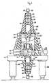
- the infinity corrected optical microscope comprises an optical imaging system (consisting of photometric iris 17, relay lens support fixture 18, relay lens 19, TV camera support fixture 20, and TV camera 21), an optical photometric system (straight tube 28, photometric iris 29, relay lens fixture 30, relay lens 31, photometric system support fixture 32, and photometric system 33),an illumination system (incident-light fluorescence 12 total internal reflection fluorescence, transmitted light fluorescence, incident polarized light transmitted polarized light, bright field incidence, optical tweezers port, 10 and 11 etc.), and the infinity corrected objective lens 2 and imaging lens 16 built into the optical lighting system.
- a hollow conical support base 7 is fixed on the vibration isolating table 15, which is supported by support legs 38.
- the optical tweezers port 10, incident-light fluorescence equipment 12, and optical monitor system 13 are installed on the expanded section below said support base 7, facing toward the center.
- the optical tweezers illumination system 11, mounted on the vibration isolating table 15, is connected to the optical tweezers port 10.
- the base 14, with imaging lens 116 at the center, is installed at the lower part of the hollow section of said support base 7.
- the flat part 39 of said base 14 rests on the vibration isolating table 15 while its leg 40 is inserted into the center of the vibration isolating table 7.
- Support stands 9 are set on said base 14, supporting a substrate 8 at the top.
- a mounting base 6, Y-axis coarse transfer base 5, X-axis coarse transfer base 4, and X-, Y-, Z-axis finely adjustable sample base 3 are installed on said substrate in this order.
- the sample 1 to be observed is placed on said X-, Y-, Z-axis finely adjustable sample base, and is illuminated by said lighting system.
- the transmitted light illumination system 23, dark field illuminator 26, and optical monitor system (b) 27 are mounted on the narrower section at the upper part of the support base 7, facing toward the center.
- the condenser lens 22 is mounted on the tip of the condenser lens support fixture 24, which is fixed on the support base 7.
- the imaging lens 25 for the lighting system is mounted on the flat part of the tip of the support base 7 at the center.
- a hollow and inverted trapezoidal support structure 41 is mounted on the bottom face of the vibration isolating table 15.
- the hollow section of the support structure 41 accommodates, as installed, the photometric iris 17, relay lens support fixture 18, relay lens 19, TV camera support fixture 20, and TV camera 21 in this order, generating the primary 34 and the secondary 35 image on the imaging side.
- the highly stable optical microscope of this invention features a construction in which the infinity corrected objective lens 2, imaging lens 16, imaging lens 25 for the lighting system, optical imaging system (consisting of the photometric iris 17, relay lens support fixture 18, relay lens 19, TV camera support fixture 20, and TV camera 21), and the optical photometric system (consisting of the straight tube 28, photometric iris 29, relay lens fixture 30, relay lens fixture 31, photometric system support fixture 32, and photometric system 33) are mounted without deviation, while forming a straight line, on the straight guide mechanism that is symmetrical about the optical axis in both shape and mass.
- the infinity corrected system is integrated into the mechanism of this invention, and the optical imaging and photometric systems each have an integrated imaging lens.
- This allows utilization of the merit of a telescope in that translation does not lead to defocusing or movement (drift) of the object point (object) during observation for extended times as long as inclination does not change.
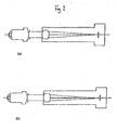
- a typical example of this straight guide mechanism comprises a cylinder and a column. The cylindrical section is movable in the direction of the optical axis.
- the sample is focused on the sample base 3 which features finely adjustable X, Y, and Z axes.
- the adjustable sample base 3 is symmetrical about the optical axis and incorporates a capacitance type sensor to feed back displacement to the piezo drive mechanism to maintain the focal position.
- a half mirror (including dichroic mirror) and an imaging lens are set on the inlet of the optical lighting system (incident-light fluorescence 12 total internal reflection fluorescence, transmitted light fluorescence, incident polarized light transmitted polarized light, bright field incidence, optical tweezers port, 10 and 11 etc.).
- the illumination system is supported by a separate support fixture independent of the optical imaging and photometric systems to assure that instability due to asymmetry of the shape and mass will not affect the optical imaging and photometric systems.
- the illumination system should be displaced due to external vibration or other causes, the sample and the objective lens are not affected by the displacement.
- the single most important factor of instability is the relative motion of the sample and objective lens.
- sample 1 infinity corrected objective lens 2
- X-, Y-, Z-axes finely adjustable sample base 3 X-axis coarse transfer base 4
- Y-axis coarse transfer base 5 Y-axis coarse transfer base 5
- mounting base 6 are respectively fixed and integrated such as by vacuum suction.
- the conventional system like a willow tree with thin trunks swaying in the wind, is replaced by a separately structured system comprising a construction like Tokyo Tower with a building directly below the Tower.
- the integrated sample and objective lens correspond to the building and are located with a low center of gravity.
- the highly stable optical microscope of this invention features an objective lens, imaging lens, optical imaging and photometric systems that are mounted without deviation, while forming a straight line, on the straight guide mechanism and support structures that are symmetrical about the optical axis in both shape and mass as described above.
- the highly stable optical microscope of this invention makes it possible to measure the position of molecules and molecular movement in the order of nanometers in molecular biology and biophysics.
- a half mirror including dichroic mirror
- an imaging lens are combined and mounted at the inlet of the illumination system (incident-light fluorescence, total internal reflection fluorescence, transmitted light, fluorescence, incident polarized light transmitted polarized light, bright field incidence, optical tweezers, etc.) and the optical monitor system.
- the illumination system incident-light fluorescence, total internal reflection fluorescence, transmitted light, fluorescence, incident polarized light transmitted polarized light, bright field incidence, optical tweezers, etc.
- This provides freedom for the mounting positions and compatibility of the respective components, enabling an optical microscope system that is expandable and highly stable.
Landscapes
- Physics & Mathematics (AREA)
- Chemical & Material Sciences (AREA)
- Analytical Chemistry (AREA)
- General Physics & Mathematics (AREA)
- Optics & Photonics (AREA)
- Engineering & Computer Science (AREA)
- Multimedia (AREA)
- Microscoopes, Condenser (AREA)
Applications Claiming Priority (3)
| Application Number | Priority Date | Filing Date | Title |
|---|---|---|---|
| JP2002073455A JP4084061B2 (ja) | 2002-03-18 | 2002-03-18 | 高安定性光学顕微鏡 |
| JP2002073455 | 2002-03-18 | ||
| PCT/JP2002/008935 WO2003079089A1 (fr) | 2002-03-18 | 2002-09-03 | Microscope optique a haute stabilite |
Publications (3)
| Publication Number | Publication Date |
|---|---|
| EP1486810A1 EP1486810A1 (en) | 2004-12-15 |
| EP1486810A4 EP1486810A4 (en) | 2007-05-23 |
| EP1486810B1 true EP1486810B1 (en) | 2009-04-29 |
Family
ID=28035240
Family Applications (1)
| Application Number | Title | Priority Date | Filing Date |
|---|---|---|---|
| EP02772834A Expired - Fee Related EP1486810B1 (en) | 2002-03-18 | 2002-09-03 | High-stability optical microscope |
Country Status (6)
| Country | Link |
|---|---|
| US (1) | US7307784B2 (ja) |
| EP (1) | EP1486810B1 (ja) |
| JP (1) | JP4084061B2 (ja) |
| CN (1) | CN100559228C (ja) |
| DE (1) | DE60232196D1 (ja) |
| WO (1) | WO2003079089A1 (ja) |
Cited By (1)
| Publication number | Priority date | Publication date | Assignee | Title |
|---|---|---|---|---|
| US9474448B2 (en) | 2010-08-27 | 2016-10-25 | The Board Of Trustees Of The Leland Stanford Junior University | Microscopy imaging device with advanced imaging properties |
Families Citing this family (10)
| Publication number | Priority date | Publication date | Assignee | Title |
|---|---|---|---|---|
| JP4558366B2 (ja) * | 2004-03-30 | 2010-10-06 | オリンパス株式会社 | システム顕微鏡 |
| DE102005001102B4 (de) * | 2005-01-08 | 2021-04-29 | Carl Zeiss Microscopy Gmbh | Temperierbares Objektiv für Mikroskope |
| US20070178012A1 (en) * | 2005-07-19 | 2007-08-02 | Ferrante Anthony A | Side view imaging microwell array |
| US7854524B2 (en) * | 2007-09-28 | 2010-12-21 | Anorad Corporation | High stiffness low mass supporting structure for a mirror assembly |
| EP2246725A3 (en) * | 2009-04-30 | 2011-01-26 | Olympus Corporation | Microscope with fixed imaging unit and movable objective lens |
| DE202009010772U1 (de) | 2009-08-11 | 2009-11-26 | Deutsches Krebsforschungszentrum Stiftung des öffentlichen Rechts | Anordnung zur Abbildungsstabilisierung |
| US9428384B2 (en) * | 2011-01-18 | 2016-08-30 | Jizhong He | Inspection instrument |
| JP6849405B2 (ja) * | 2016-11-14 | 2021-03-24 | 浜松ホトニクス株式会社 | 分光計測装置及び分光計測システム |
| CN108414446A (zh) * | 2018-03-30 | 2018-08-17 | 广东顺德墨赛生物科技有限公司 | 微流控芯片荧光检测设备、方法以及装置 |
| CN110888230A (zh) * | 2019-11-28 | 2020-03-17 | 天津职业技术师范大学(中国职业培训指导教师进修中心) | 一种智能生物显微镜 |
Family Cites Families (14)
| Publication number | Priority date | Publication date | Assignee | Title |
|---|---|---|---|---|
| US3259012A (en) * | 1960-09-12 | 1966-07-05 | Inv S Finance Corp | Microscope having bridge type support arm for body tube and focusing mechanism |
| GB1260653A (en) * | 1968-01-25 | 1972-01-19 | Watson W & Sons Ltd | Improvements in or relating to optical apparatus |
| US3830560A (en) * | 1970-09-14 | 1974-08-20 | R Onanian | Microscope apparatus |
| JPS5524566Y2 (ja) * | 1975-10-28 | 1980-06-12 | ||
| US5317153A (en) * | 1991-08-08 | 1994-05-31 | Nikon Corporation | Scanning probe microscope |
| JP3431309B2 (ja) | 1994-10-14 | 2003-07-28 | オリンパス光学工業株式会社 | 倒立形顕微鏡用保温装置 |
| JP2966311B2 (ja) * | 1995-03-10 | 1999-10-25 | 科学技術振興事業団 | 顕微測光装置 |
| JP3221823B2 (ja) * | 1995-11-24 | 2001-10-22 | キヤノン株式会社 | 投影露光装置およびこれを用いた露光方法ならびに半導体製造方法 |
| US5764409A (en) * | 1996-04-26 | 1998-06-09 | Alpha Innotech Corp | Elimination of vibration by vibration coupling in microscopy applications |
| CN100356163C (zh) * | 1996-08-16 | 2007-12-19 | Ge保健尼亚加拉公司 | 用于分析井板、凝胶和斑点的数字成像系统 |
| US6091911A (en) * | 1996-08-30 | 2000-07-18 | Nikon Corporation | Microscope photographing unit with brightness control for observation optical system |
| JP3437406B2 (ja) * | 1997-04-22 | 2003-08-18 | キヤノン株式会社 | 投影露光装置 |
| US5970260A (en) * | 1997-09-10 | 1999-10-19 | Konica Corporation | Camera equipped with zoom lens |
| CA2243090A1 (en) * | 1998-07-10 | 2000-01-10 | Timothy M. Richardson | Inverted darkfield contrast microscope and method |
-
2002
- 2002-03-18 JP JP2002073455A patent/JP4084061B2/ja not_active Expired - Fee Related
- 2002-09-03 WO PCT/JP2002/008935 patent/WO2003079089A1/ja active Application Filing
- 2002-09-03 DE DE60232196T patent/DE60232196D1/de not_active Expired - Lifetime
- 2002-09-03 CN CNB028285794A patent/CN100559228C/zh not_active Expired - Fee Related
- 2002-09-03 EP EP02772834A patent/EP1486810B1/en not_active Expired - Fee Related
- 2002-09-03 US US10/506,107 patent/US7307784B2/en not_active Expired - Fee Related
Cited By (2)
| Publication number | Priority date | Publication date | Assignee | Title |
|---|---|---|---|---|
| US9474448B2 (en) | 2010-08-27 | 2016-10-25 | The Board Of Trustees Of The Leland Stanford Junior University | Microscopy imaging device with advanced imaging properties |
| US9498135B2 (en) | 2010-08-27 | 2016-11-22 | The Board Of Trustees Of The Leland Stanford Junior University | Microscopy imaging device with advanced imaging properties |
Also Published As
| Publication number | Publication date |
|---|---|
| EP1486810A1 (en) | 2004-12-15 |
| DE60232196D1 (de) | 2009-06-10 |
| US7307784B2 (en) | 2007-12-11 |
| JP2003270537A (ja) | 2003-09-25 |
| EP1486810A4 (en) | 2007-05-23 |
| CN1623110A (zh) | 2005-06-01 |
| WO2003079089A1 (fr) | 2003-09-25 |
| US20050117204A1 (en) | 2005-06-02 |
| CN100559228C (zh) | 2009-11-11 |
| JP4084061B2 (ja) | 2008-04-30 |
Similar Documents
| Publication | Publication Date | Title |
|---|---|---|
| US8624967B2 (en) | Integrated portable in-situ microscope | |
| EP1486810B1 (en) | High-stability optical microscope | |
| US6285498B1 (en) | High-precision computer-aided microscope system | |
| JP2001241940A (ja) | 基板上の特徴を測定するための測定装置及び測定方法 | |
| JP2001521182A (ja) | 高精度コンピュータ利用顕微鏡装置 | |
| JP2006189642A (ja) | 実体顕微鏡 | |
| US7180662B2 (en) | Stage assembly and method for optical microscope including Z-axis stage and piezoelectric actuator for rectilinear translation of Z stage | |
| WO2018087665A1 (en) | Portable upright bright field microscope with smart device compatibility | |
| JP7025530B2 (ja) | 広領域の共焦点及び多光子顕微鏡で用いる動的フォーカス・ズームシステム | |
| JP2002048978A (ja) | 対物レンズユニット、対物レンズユニットを有する光学装置及びその光学装置を用いた観察方法 | |
| JP2009145843A (ja) | 顕微鏡照明光学系 | |
| US7298549B2 (en) | Microscope | |
| CN110307805A (zh) | 一种用于表面三维形貌测量的白光干涉系统 | |
| TWI269886B (en) | Microscope and specimen observation method | |
| JP6978592B2 (ja) | 広領域の共焦点及び多光子顕微鏡で用いる動的フォーカス・ズームシステム | |
| US10775600B2 (en) | Smart media device platform as an inverse microscopic imaging apparatus | |
| US6785045B2 (en) | Microscope focusing apparatus | |
| JP4819989B2 (ja) | 顕微鏡 | |
| JP2001264641A (ja) | 倒立顕微鏡 | |
| CN111344620B (zh) | 用于宽场、共焦和多光子显微镜的动态聚焦和变焦系统 | |
| KR100471598B1 (ko) | 다양한 영상매체에서 동시 관찰이 가능한 현미경 | |
| KR20230016496A (ko) | 현미경용 얼라인 장치 | |
| JPH09145721A (ja) | 光学顕微鏡一体型走査型プローブ顕微鏡 | |
| JP2001083430A (ja) | 倒立顕微鏡装置 | |
| Moore et al. | The MOMFOS fiber positioner |
Legal Events
| Date | Code | Title | Description |
|---|---|---|---|
| PUAI | Public reference made under article 153(3) epc to a published international application that has entered the european phase |
Free format text: ORIGINAL CODE: 0009012 |
|
| 17P | Request for examination filed |
Effective date: 20040920 |
|
| AK | Designated contracting states |
Kind code of ref document: A1 Designated state(s): AT BE BG CH CY CZ DE DK EE ES FI FR GB GR IE IT LI LU MC NL PT SE SK TR |
|
| A4 | Supplementary search report drawn up and despatched |
Effective date: 20070424 |
|
| 17Q | First examination report despatched |
Effective date: 20080328 |
|
| GRAP | Despatch of communication of intention to grant a patent |
Free format text: ORIGINAL CODE: EPIDOSNIGR1 |
|
| GRAP | Despatch of communication of intention to grant a patent |
Free format text: ORIGINAL CODE: EPIDOSNIGR1 |
|
| GRAS | Grant fee paid |
Free format text: ORIGINAL CODE: EPIDOSNIGR3 |
|
| GRAA | (expected) grant |
Free format text: ORIGINAL CODE: 0009210 |
|
| AK | Designated contracting states |
Kind code of ref document: B1 Designated state(s): DE GB NL |
|
| REG | Reference to a national code |
Ref country code: GB Ref legal event code: FG4D |
|
| REF | Corresponds to: |
Ref document number: 60232196 Country of ref document: DE Date of ref document: 20090610 Kind code of ref document: P |
|
| NLS | Nl: assignments of ep-patents |
Owner name: JAPAN SCIENCE AND TECHNOLOGY AGENCY Effective date: 20090902 |
|
| PLBE | No opposition filed within time limit |
Free format text: ORIGINAL CODE: 0009261 |
|
| STAA | Information on the status of an ep patent application or granted ep patent |
Free format text: STATUS: NO OPPOSITION FILED WITHIN TIME LIMIT |
|
| 26N | No opposition filed |
Effective date: 20100201 |
|
| PGFP | Annual fee paid to national office [announced via postgrant information from national office to epo] |
Ref country code: DE Payment date: 20140812 Year of fee payment: 13 Ref country code: NL Payment date: 20140811 Year of fee payment: 13 |
|
| PGFP | Annual fee paid to national office [announced via postgrant information from national office to epo] |
Ref country code: GB Payment date: 20140811 Year of fee payment: 13 |
|
| REG | Reference to a national code |
Ref country code: DE Ref legal event code: R119 Ref document number: 60232196 Country of ref document: DE |
|
| GBPC | Gb: european patent ceased through non-payment of renewal fee |
Effective date: 20150903 |
|
| REG | Reference to a national code |
Ref country code: NL Ref legal event code: MM Effective date: 20151001 |
|
| PG25 | Lapsed in a contracting state [announced via postgrant information from national office to epo] |
Ref country code: GB Free format text: LAPSE BECAUSE OF NON-PAYMENT OF DUE FEES Effective date: 20150903 Ref country code: DE Free format text: LAPSE BECAUSE OF NON-PAYMENT OF DUE FEES Effective date: 20160401 |
|
| PG25 | Lapsed in a contracting state [announced via postgrant information from national office to epo] |
Ref country code: NL Free format text: LAPSE BECAUSE OF NON-PAYMENT OF DUE FEES Effective date: 20151001 |