EP1486783B1 - Vorrichtung und Verfahren zur Elektrophorese - Google Patents
Vorrichtung und Verfahren zur Elektrophorese Download PDFInfo
- Publication number
- EP1486783B1 EP1486783B1 EP04102122A EP04102122A EP1486783B1 EP 1486783 B1 EP1486783 B1 EP 1486783B1 EP 04102122 A EP04102122 A EP 04102122A EP 04102122 A EP04102122 A EP 04102122A EP 1486783 B1 EP1486783 B1 EP 1486783B1
- Authority
- EP
- European Patent Office
- Prior art keywords
- cassette
- electrophoresis
- gel
- cassette according
- driving
- Prior art date
- Legal status (The legal status is an assumption and is not a legal conclusion. Google has not performed a legal analysis and makes no representation as to the accuracy of the status listed.)
- Expired - Lifetime
Links
Images


Classifications
-
- G—PHYSICS
- G01—MEASURING; TESTING
- G01N—INVESTIGATING OR ANALYSING MATERIALS BY DETERMINING THEIR CHEMICAL OR PHYSICAL PROPERTIES
- G01N27/00—Investigating or analysing materials by the use of electric, electrochemical, or magnetic means
- G01N27/26—Investigating or analysing materials by the use of electric, electrochemical, or magnetic means by investigating electrochemical variables; by using electrolysis or electrophoresis
- G01N27/416—Systems
- G01N27/447—Systems using electrophoresis
- G01N27/44704—Details; Accessories
- G01N27/44717—Arrangements for investigating the separated zones, e.g. localising zones
- G01N27/44721—Arrangements for investigating the separated zones, e.g. localising zones by optical means
-
- B—PERFORMING OPERATIONS; TRANSPORTING
- B01—PHYSICAL OR CHEMICAL PROCESSES OR APPARATUS IN GENERAL
- B01D—SEPARATION
- B01D57/00—Separation, other than separation of solids, not fully covered by a single other group or subclass, e.g. B03C
- B01D57/02—Separation, other than separation of solids, not fully covered by a single other group or subclass, e.g. B03C by electrophoresis
-
- G—PHYSICS
- G01—MEASURING; TESTING
- G01N—INVESTIGATING OR ANALYSING MATERIALS BY DETERMINING THEIR CHEMICAL OR PHYSICAL PROPERTIES
- G01N27/00—Investigating or analysing materials by the use of electric, electrochemical, or magnetic means
- G01N27/26—Investigating or analysing materials by the use of electric, electrochemical, or magnetic means by investigating electrochemical variables; by using electrolysis or electrophoresis
- G01N27/416—Systems
- G01N27/447—Systems using electrophoresis
- G01N27/44704—Details; Accessories
Definitions
- the present invention relates to electrophoresis generally and more particularly to apparatus for conducting an electrophoresis test therein.
- RNA, RNA or proteins are separated according to their physical and chemical properties via electrophoresis.
- This process is widely used and has many applications. For example, it is used to analyze DNA molecules according to their resultant size after being digested by restriction enzymes. It is also used to analyze the products of a polymerase chain reaction (PCR).
- PCR polymerase chain reaction
- electrophoresis separation is carried out in a separation medium, such as a gel of agarose or acrylamide or a combination of the two.
- a separation medium such as a gel of agarose or acrylamide or a combination of the two.
- agarose gels are cast in open trays and form a slab whereas acrylamide gels are cast between two glass plates.
- an electrically conducting buffer which is connected by electrodes, typically carbon or platinum, to an electric power source. Once the electrical power source is switched on, the electric field forces negatively charged molecules to move towards the anode and positively charged molecules to move towards the cathode.
- electrodes typically carbon or platinum
- One characteristic of conventional electrophoresis is the use of large volumes of buffer having a relatively low salt concentration to maintain the required electric field.
- DNA is negatively charged and therefore, in the agarose or acrylamide gels which provide sieving action, DNA molecules move towards the anode at a rate which depends on their size, wherein the smaller the molecules the faster they move.
- Prior art electrophoresis separation systems are a potential source of contamination to the working environment in which the tests are performed.
- the two major sources of contamination are ethidium bromide and PCR products.
- Ethidium bromide is a hazardous chemical due to its mutagenic activity and therefore, exposure to ethidium bromide may induce malignant tumors.
- PCR is an extremely sensitive method to the extent that a single molecule of DNA product from one PCR (out of the trillions of molecules being produced) may interfere with the subsequent PCR such that it will produce incorrect result.
- US Patent 5,407,552 to Lebacq describes an electrophoresis device having a single-piece cartridge made from a section of a hollow shape having two opposite open sides, one of which is sealed by a removable comb element whilst the other is sealed by a removable cover.
- a major object of the present invention is to provide a closed cassette for electrophoresis which is substantially closed before, during and after an electrophoresis test conducted therein.
- the cassette of the present invention overcomes drawbacks associated with prior art electrophoresis cassettes, plates or slabs. Since the cassette is a closed one, its outer environment is not susceptible to contamination. Moreover, since it is ready to use, the preparation time required for preparing prior art cassettes is saved.
- Another object of the present invention is to provide an electrophoresis system in which both the electrophoretic separation and the visualization of the results thereof are done while the cassette is in situ.
- the present invention provides a substantially closed cassette for conducting electrophoresis therein, the cassette comprising: a housing having at least bottom and side walls defining a chamber, wherein said chamber comprises, in contact therebetween: a body of separating gel for carrying out therein said electrophoresis comprising one or more wells; at least one ion source having a volume smaller than the volume of said body of separating gel, and electrodes for connecting said chamber to an external electrical power source, to enable driving said electrophoresis; and a cover closing said chamber to provide the substantially closed cassette, wherein said cover or said chamber comprises at least one opening over said one or more wells.
- the present invention provides an electrophoresis method comprising the steps of: introducing a test sample into a body of separating gel through at least one opening in a cover of a substantially closed cassette, the cassette comprising said body of separating gel and at least one ion source having a volume smaller than the volume of said body of separating gel; applying an electrical field to said gel; and driving electrophoresis by providing ions required for driving said electrophoresis by the at least one ion source within said substantially closed cassette.
- the present invention provides an electrophoresis system comprising: a cassette of the invention; and a holder for said cassette wherein said holder comprises contact points for said electrodes.
- Included in the invention is a substantially closed disposable cassette with openings for introducing a sample of molecules thereinto, the openings being preferably opened only just before the electrophoresis test.
- Included in the invention is a cassette that includes all the chemical compounds required to drive the electrophoretic separation, and, when DNA molecules are separated, the compounds required to stain the separated DNA.
- the volume of the ion source utilized for providing the ions required for the electrophoresis separation is smaller than the volume of the gel utilized as the electrophoresis separation matrix and preferably smaller than the volume of gel utilized for actual separation during an electrophoresis test.
- the ions (cations and anions) required to drive the electrophoretic separation are provided by a cation exchange matrix and an anion exchange matrix, respectively.
- the cation exchange matrix also provides the cations required to stain the separated molecules in order to enable visualization thereof when the cassette is illuminated with a UV light source.
- the ions required to drive the electrophoresis separation are provided by a reservoir, preferably a breakable ampoule containing a buffer characterized by relatively high concentration of these ions.
- One advantage of the cassette of the present invention is that it is disposable.
- cassette of the present invention is that the user is not exposed to any hazardous chemical constituent, such as ethidium bromide, as in prior art cassettes.
- cassette of the present invention is that PCR-DNA products are contained within the cassette and are disposed therewith so as to substantially reduce the contamination of the working environment in which the tests are performed.
- an apparatus for conducting electrophoresis separation therein which includes a housing having at least bottom and side walls defining a chamber, wherein the chamber includes in contact therebetween a body of gel for carrying out therein the electrophoresis separation, at least one ion source for providing ions for driving the electrophoresis, the at least one ion source having a volume smaller than the volume of the body of gel, and electrodes for connecting the chamber to an external electrical power source, thereby enabling to drive the electrophoresis separation.
- a substantially closed cassette for conducting therein electrophoresis separation which includes a closed chamber which includes therein a body of gel for carrying out therein the electrophoresis separation, at least one ion source for providing ions for driving the electrophoresis separation, and electrodes for connecting the cassette to an external electrical power source, thereby enabling to drive the electrophoresis separation.
- an apparatus for conducting electrophoresis separation therein which includes a housing having at least bottom and side walls defining a chamber which includes in contact therebetween a body of gel for carrying out therein said electrophoresis separation, at least one body of ion exchange matrix for providing ions for driving the electrophoresis separation, and electrodes for connecting the chamber to an external electrical power source, thereby enabling to drive the electrophoresis separation.
- the volume of the at least one ion source is smaller than the volume of the body of gel utilized in the electrophoresis separation.
- the at least one ion source includes a body of ion exchange matrix.
- the body of ion exchange matrix includes a body of cation exchange matrix for providing the cations for driving the electrophoresis separation and a body of anion exchange matrix for providing the anions for driving the electrophoresis separation.
- the cation exchange matrix is disposed at one end of the body of separating gel and the body of anion exchange matrix is disposed on a second end of the separating gel.
- the cation exchange matrix exchanges protons derived from electrolysis with the cations for driving the electrophoretic separation and the anion exchange matrix exchanges hydroxyl ions derived from the electrolysis with the anions for driving the electrophoretic separation.
- the cation exchange matrix and the anion exchange matrix includes particles immersed in a support matrix.
- the support matrix is formed of the gel as the body of gel for carrying out the electrophoresis separation therein.
- the apparatus also include an additional body of gel of low gel strength disposed between the side wall of the chamber and the anion exchange matrix, the body of gel of low gel strength shrinking during the electrophoresis separation, thereby providing a volume in which gases produced at the vicinity of an anode of the chamber accumulates.
- the apparatus includes a buffer solution in contact with the body of separating gel, the at least one body of ion exchange matrix and the electrodes.
- the buffer is a TAE buffer, thus the cation exchange matrix releases Tris cations and the anion exchange matrix releases acetate anions.
- the cation exchange matrix includes ethidium cations.
- the least one ion source includes a closed reservoir having therein a buffer solution having higher concentration than a concentration of a buffer solution of the body of gel for carrying out therein the electrophoresis separation, the closed reservoir being opened just before the electrophoresis separation for providing the ions for driving the electrophoresis separation.
- the closed reservoir is a breakable ampoule.
- the breakable ampoule may be surrounded by a space, the space at least partially filled with the buffer solution in a concentration generally similar to that of the body of gel for carrying out therein the electrophoresis separation.
- the buffer is a TAE buffer.
- the buffer may also include ethidium cations.
- the chamber or the cover may include at least one opening therein for introducing at least one test sample into the body of gel.
- the at least one opening is closed by a comb prior to the electrophoresis separation.
- the chamber and/or the cover may be transparent to ultra violet (UV) radiation.
- UV ultra violet
- the chamber or cover may also include at least one vent hole which is closed prior to the electrophoresis test and is being opened just before the electrophoresis test.
- the electrodes include a conductive material capable of adsorbing at least part of at least one of the gases produced during the electrophoresis separation.
- the at least one electrode capable of adsorbing is substantially formed from a material selected from the group consisting of aluminum and palladium.
- the gases include oxygen created at the vicinity of the anode during the electrophoresis separation and reacting with the aluminum.
- the gases include hydrogen created at the vicinity of the cathode during the electrophoresis separation and wherein the hydrogen is adsorbed by the palladium.
- the at least one electrodes includes a strip of conductive material.
- the strip of conductive material is mounted on a ramp, the ramp being inclined at an angle relative to the bottom wall, whereby gases produced at the vicinity of the strip during the electrophoresis separation are being directed to an empty volume receiving the gases.
- the apparatus or cassette may also include at least one empty volume for accumulating gases produced during the electrophoresis test.
- a system for conducting electrophoresis separation which includes an electrical power source, a substantially closed disposable cassette, preferably, but not necessarily the apparatus or cassette of the present invention, and a support for supporting the substantially closed cassette and for connecting the electrical power source to the conductive elements of the cassette.
- the system may also include a UV light source and wherein the cassette is transparent to UV light, and wherein the cassette also includes a UV sensitive material capable of interacting with the molecules undergoing electrophoresis separation and of emitting light, thereby enabling to conduct the electrophoresis separation and to visualize it while the cassette is in situ.
- the UV sensitive material is ethidium bromide.
- the system may also include camera means for documenting the results of the electrophoresis separation.
- the system may also include a computer which includes at least one image analysis application for analyzing the results of the electrophoresis separation.
- system may include a cooling system for cooling the cassette during the electrophoresis test.
- an electrophoresis method which includes the steps of introducing at least one test sample into a body of gel, applying an electrical field to the body of gel and driving an electrophoresis separation by providing ions required for driving the electrophoresis separation by at least one ion source having a volume smaller than the volume of the gel.
- a method for producing a substantially closed cassette for conducting electrophoresis separation therein which includes the steps of providing a housing having bottom and side walls defining an open chamber, assembling within the chamber in contact therebetween a body of gel for carrying out therein the electrophoresis separation, at least one ion source for providing ions for driving the electrophoresis separation, the at least one ion source having a volume smaller than that of the body of gel and electrodes for connecting the chamber to an external electrical power source, and closing the open housing with a cover, thereby forming a substantially closed cassette capable of carrying out the electrophoresis separation therein.
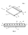
- FIG. 1 - 4 illustrate an electrophoresis disposable cassette, generally referenced 10, constructed and operative in accordance with a preferred embodiment of the present invention.
- Cassette 10 is a closed disposable cassette preferably, but not necessarily, used for a single electrophoresis test.
- Cassette 10 includes all the chemical compounds required for driving the electrophoresis separation and for enabling visualization of its results when DNA as well as RNA or protein molecules have been separated.
- the cassette 10 preferably comprises a three dimensional chamber 11 which is preferably substantially flat, having bottom wall and side walls, referenced 12 and 14 respectively, and a cover 16 which forms the top wall of the cassette.
- the bottom wall 12 ( Fig. 4 ) and the cover 16 are preferably made of any suitable UV transparent material, such as the TPX plastic commercially available from MITSUI of Japan or the PMMA plastic, commercially available from Repsol Polivar S.P.A. of Rome.
- a plastic molding process is employed utilizing a Rohaglas Molding Powder, commercially available from Sidas GmbH of Damstadt, Germany.
- chamber 11 preferably comprises a gel matrix 18 which may be any suitable gel matrix for electrophoresis, such as an agarose gel or a gel made of acrylamide, a cation exchange matrix 20 and an anion exchange matrix 22, collectively referred to as the ion exchange matrices 20 and 22.
- Chamber 11 further comprises two conductive rods referenced 24 and 26, such as stainless steel rods which, when connected to an external direct current (DC) electrical power source, provide the electric field required to drive electrophoretic separation.
- rod 24 is the anode and rod 26 is the cathode.
- Chamber 11 further comprises two empty volumes 28 and 30, in which gases produced during the electrophoresis test may accumulate.
- the open cover 16 may include two vent holes 32 and 34, shown only in Fig. 3 , for venting the gases accumulated in the empty volumes 28 and 30.
- a particular feature of cassette 10, as best shown in Figs. 3 and 4 is that the volume of the ion source, the ion exchange matrices 20 and 22 in the illustrated embodiment, is smaller than the volume of the gel 18 utilized as the electrophoresis separation matrix and preferably smaller than the volume of gel utilized for actual separation during an electrophoresis test.
- cassette 10 includes vent holes 32 and 34 they are sealed prior to the beginning of the electrophoretic test, and are opened just before the electrophoresis test begins and are closed again after the test is completed to substantially reduce the possibility of contamination originated therefrom.
- each of the gel 18, the ion exchange matrices 20 and 22 and the conductive rods 24 and 26 are in contact and are immersed in a relatively small amount of an agarose matrix produced and including a buffer solution, such as a TAE buffer, which facilitates the mobility of the molecules undergoing separation and of the ions provided by the ion exchange matrices 20 and 22.
- a buffer solution such as a TAE buffer
- the ions required for driving the electrophoretic separation are provided by the ion exchange matrices 20 and 22, preferably, by exchanging with protons and hydroxyl ions derived from electrolysis of H 2 O.
- a DC current is applied via rods 24 and 26 to initiate the electrolysis which in turn initiates the operation of the ion exchange matrices.
- the cation exchange matrix 20 and the anions exchange matrix 22 release the cations and anions required for driving electrophoresis separation.
- An example of a suitable cation is the Tris (+) cation and an example of a suitable anion is acetate (-) .
- the ions released by the ion exchange matrices 20 and 22 are exchanged with adsorbed protons and hydroxyl anions, respectively.
- the ions adsorbed by the ion exchange matrices 20 and 22 may also be provided by the rods 24 and 26.
- the use of the ion exchange matrices 20 and 22 provides a generally uniform pH throughout the cell since any proton buildup near the anode 24 is compensated by absorption thereof by the neighboring cation exchange matrix 20 and hydroxyl buildup near the cathode 26 is compensated by absorption thereof by the anion exchange matrix 22.
- the cation exchange matrix 20 and the anions exchange matrix 22 may be immersed in one of the materials used for preparing the gel.
- a suitable cation exchange material is the CM-25-120 Sephadex and suitable anion exchange materials are the WA-30 and the A-25-120, all of which are commercially available from Sigma Inc. of St. Louis, U.S.A.
- Cassette 10 preferably also includes wells 36 in the gel 18.
- Wells 36 are used to introduce samples of the molecules which are to undergo electrophoretic separation.
- the wells 36 may be formed by any suitable method, such as by introducing a comb like structure 40 ( Fig. 2 ) to the gel during the assembly of the gel.
- the comb 40 is introduced to the gel via corresponding openings 38 ( Fig. 1 ) in the cover 16.
- the openings 38 may be used as an additional space for loading the molecular samples just before the onset of the electrophoresis test after the comb 40 is removed.
- the wells 36 are covered by the comb 40 used in their preparation. This is since the comb method involves insertion of a comb structure into the gel via the openings 38 in the top cover 16, the comb being pulled out only just before the electrophoresis test.
- the cassette 10 is a closed cassette covered by the comb 40 which is removed just before the electrophoresis test itself.
- the cassette 10 also includes a source for ethidium cations which are used for ultra violet (UV) visualization of the separated DNA molecules.
- a source for ethidium cations which are used for ultra violet (UV) visualization of the separated DNA molecules.
- the cassette 10 includes an internal source for ethidium ions source.
- the cation exchange matrix 20 releases not only the TRIS cations but also ethidium cations which interact with the molecules undergoing electrophoretic separation.
- the cation exchange matrix 20 provides a continuous flux of ethidium cations during the electrophoresis test so as to stain the DNA molecules so as to enable their visualization and analysis, in situ, utilizing a suitable electrophoresis system, such as the system described with reference to Fig. 16 hereinbelow.
- the following examples which are not intended to limit the scope of the present invention, illustrate how the cation exchange matrix 20 and the anion exchange matrix 22 are prepared.
- the following example is for a cassette whose outer length, width and height are 100 millimeters (mm), 80mm and 6mm, respectively. It will be appreciated that a cassette of these outer dimensions is substantially flat.
- the cation exchange matrix 20 was prepared as follows:
- the anion exchange matrix 22 is prepared as follows:
- the cation exchange matrix 20 is prepared as follows:
- the anion exchange matrix 22 was prepared as follows:
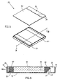
- FIG. 5 and 6 illustrate an electrophoresis cassette, generally referenced 25, constructed and operative in accordance with a second preferred embodiment of the present invention.
- Cassette 25 is generally similar in construction and operation to cassette 10 ( Figs. 1 - 4 ), i.e. it is a closed disposable cassette preferably used for a single electrophoresis test which comprises a gel 18 and an ion exchange matrices 20 and 22. Therefore similar elements of cassettes 10 and 25 are referenced by similar reference numerals (e.g. comb 40).
- Chamber 60 comprises similar to chamber 11 a gel matrix 18 and an ion exchange matrices 20 and 22. However, chamber 60 differs from chamber 11 in construction and operation with respect to the anode and cathode and the gas accumulation and venting mechanism.
- Chamber 60 comprises two conductive strips 21 and 23 which form the cathode and anode, respectively.
- Cathode 21 is diagonally supported by a diagonal ramp 27, ramp 27 preferably forms an integral part of chamber 60.
- Anode 23 is positioned under ion exchange matrix 20 and an additional gel matrix 29 which shrinks during electrophoresis due to electroendosmosis as described in detail hereinbelow.
- Gel matrix 29 is preferably the same gel as gel matrix 18, however its gel strength is lower than that of gel 18.
- gel matrix 18 is comprised of 2% agarose while the gel matrix 29 comprises 0.3% agarose.
- cathode 21 and anode 23 are made of a conductive material that is capable of adsorbing gases produced during the electrophoretic separation process.
- cathode 21 and anode 23 are made of aluminum.
- the oxygen produced at the vicinity of anode 23 reacts with the aluminum anode to form aluminum oxide, whereby less free oxygen is produced at the anode side.
- the reduction in the volume of gas produced, together with the space created for gas accumulation by the shrinkage of gel matrix 29, alleviates the need for a vent hole in the anode side of cassette 25.
- cassette 25 may include in its cover 62 only a single vent hole 35 above empty volume 30 which is adjacent to the cathode.
- the anode is made of aluminum as described hereinabove whereas the cathode is formed of palladium or any other suitable conductive material which adsorbs hydrogen at the cathode side.
- cassette 25 is diagonally supported by ramp 27. This facilitates continuous contact between the cathode and the surface of the anion exchange matrix 22 overlying cathode 21, whereby release of gas bubbles produced at the vicinity of cathode 21 are directed towards empty volume 30.
- ramp 27 is formed as an integral part of chamber 60 and is inclined to the bottom wall 12 at an angle of about 45 degrees.
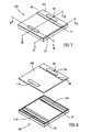
- FIG. 7 - 11 illustrate an electrophoresis cassette, generally referenced 125, constructed and operative in accordance with yet another preferred embodiment of the present invention.
- Cassette 125 similarly to cassettes 10 and 25 is a closed disposable cassette used for a single electrophoresis test and including all the chemical compounds required for driving the electrophoresis separation and for enabling visualization of its results when DNA as well as RNA or protein molecules have been separated.
- Cassette 125 comprises a three dimensional chamber 160 generally similar to chamber 60 of cassette 25 and a cover 162 generally similar to cover 62 of cassette 25. Cassette 125 differs from cassette 25 in its ion source for driving the electrophoresis separation.
- elements which are generally similar to elements of cassettes 10 and 25 are designated by similar reference numerals (e.g. gel 18).
- the body of gel 18 is disposed intermediate two spaces 120 and 122 containing a buffer solution, such as the TAE buffer solution described hereinabove.
- a buffer solution such as the TAE buffer solution described hereinabove.
- Each of volumes 120 and 122 comprises therein a closed reservoir which includes the same buffer however in a higher concentration so as to provide the ions for driving the electrophoresis separation.
- the closed reservoirs are breakable ampoules 116 and 134 including buffer solutions 124 and 132, respectively which are of higher concentration than that of volumes 120 and 122.
- the concentration of solutions 124 and 132 is fifty fold higher than that of the buffer solutions of spaces 120 and 122.
- ampoules 116 and 134 are formed of any sealed suitable material impermeable to water, such as plastic or glass, thus the concentrated buffer solutions 124 and 132 therein are not in contact with the buffer solutions filling volumes 120 and 122.
- ampoules 116 and 134 are supported by ampoule supports 106.
- the user breaks ampoules 116 and 134 so as to provide the ions in the high concentration buffers 124 and 132, respectively, in order to provide the ions required to run the electrophoresis test, preferably, after the DC current is provided to cassette 125.
- each of ampoules 116 and 134 is supported under a flexible cover 110.
- Flexible covers 110 are formed of any flexible material responsive to mechanical force, such as rubber, so as to enable breaking of ampoules 116 and 134 once pressure is applied thereon, thereby releasing their contents into buffer spaces 120 and 122 respectively.
- concentrated buffer solution 124 also contains a suitable material for DNA staining, preferably any source for ethidium cations, such as ethidium bromide so as to enable UV visualization of the separated DNA samples as described hereinabove.
- a suitable material for DNA staining preferably any source for ethidium cations, such as ethidium bromide so as to enable UV visualization of the separated DNA samples as described hereinabove.
- chamber 160 is formed of a UV transparent material.
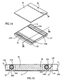
- FIG. 12 - 15 illustrate an electrophoresis cassette, generally referenced 225, constructed and operative in accordance with yet another preferred embodiment of the present invention.
- Cassette 225 is similar to cassette 125 and similarly to cassettes 10 and 25 and 125 is a closed disposable cassette used for a single electrophoresis test and including all the chemical compounds required for driving the electrophoresis separation and for enabling visualization of its results when DNA as well as RNA or protein molecules have been separated.
- Cassette 225 is generally similar to cassette 125 in construction and operation and similar elements are referenced by similar reference numerals. Cassette 225 differs from cassette 125 in its ampoule and its mechanism for breaking it.
- Cassette 225 comprises two ampoules 216 and 234 generally similar to ampoules 116 and 134 which are capable of melting by passing an electric current therethrough.
- a conducting wire 240 is embedded in the wall of ampoules 216 and 234.
- conducting wire 240 is a high resistivity single wire having two ends 226 to which electric current in a closed circuit may be applied.
- ampoules 216 and 234 are melted just before the electrophoretic test is started by passing a current through conductive wire 240 by connecting an electrical power source to contacts 226.
- the portions of conductive wire 240 not embedded in ampoules 216 and 234 are coated with an insulating material so as to insulate them.
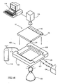
- Fig. 16 is a schematic isometric illustration of a system for conducting a plurality of electrophoresis tests and which is suitable for visualizing and documenting, in situ, the results thereof, constructed and operative in accordance with a preferred embodiment of the present invention.
- the system generally referenced 100, preferably comprises a holder or support housing 102 for supporting any of cassettes 10, 25, 125 or 225, a power supply 104 for providing the direct current (DC) required for driving the electrophoresis separation process, a cable 105 for connecting any of cassettes 10, 25, 125 and 225 to power supply 104 and an ultra violet (UV) light source 106 for illuminating the cassettes 10, 25, 125 or 225.
- DC direct current
- UV ultra violet
- Holder 102 preferably comprises two contact points (not shown) to which the rods 24 and 26 of the cassette 10, or strips 21 and 23 of cassettes 25, 125 or 225 are connected so as to provide thereto the electric field required for the electrophoresis separation.
- system 100 also comprises a second cable 107 for providing the current required to heat conductive wire 240 in case cassette 225 is used.
- holder 102 includes an additional pair of contacts to which contacts 226 of cassette 225 are connected so as to provide thereto the electric current required for the heating conductive wire 240.
- system 100 Another optional feature of system 100 is means for cooling any of cassettes 10, 25, 125, or 225, during the electrophoresis test, such as a flow of cooled gas, for example, liquid nitrogen, schematically illustrated by the balloon 112 and the tube 114.
- cooled gas for example, liquid nitrogen
- system 100 also comprise means for documenting the electrophoresis separation results.
- these include a camera, preferably a video camera 116 and a computer 119 operatively connected to camera 116 and executing any suitable application for image analysis of the results of the electrophoresis separation.
- both the electrophoresis test, the visualization of the results thereof and optionally the documentation and the analysis thereof are performed when the cassette is in situ, i.e in holder 102.
- cassettes 10, 25, 125 and 225 preferably include ethidium cations as described hereinabove so as to enable the visualization and thus the documentation and analysis of the electrophoresis test results.
- the holder 102 is a stand alone open box-like construction which includes a support surface 108 on which any of cassettes 10, 25, 125 or 225 is placed. Alternatively, it may include a UV transparent bottom surface.
- Another particular feature of the system 100 is that relative to prior art, a smaller number of operations is required from the user in order to conduct an electrophoresis test employing any of cassettes 10, 25, 125 or 225.
- These steps, for electrophoresis separation of DNA molecules include:
- any of the cassettes of the present invention may include a combination of the ion exchange matrix disposed at one side of the get 18 and the closed reservoir disposed at the other end thereof.
- Another example which is within the scope of the present invention is a two dimensional cassette in which the ion sources are disposed on all four sides of gel 18.
Landscapes
- Life Sciences & Earth Sciences (AREA)
- Health & Medical Sciences (AREA)
- Chemical & Material Sciences (AREA)
- Molecular Biology (AREA)
- Chemical Kinetics & Catalysis (AREA)
- Electrochemistry (AREA)
- Pathology (AREA)
- Immunology (AREA)
- Physics & Mathematics (AREA)
- Analytical Chemistry (AREA)
- Biochemistry (AREA)
- General Health & Medical Sciences (AREA)
- General Physics & Mathematics (AREA)
- Environmental & Geological Engineering (AREA)
- Engineering & Computer Science (AREA)
- Investigating Or Analysing Biological Materials (AREA)
- Electrostatic Separation (AREA)
- Peptides Or Proteins (AREA)
- Preparation Of Compounds By Using Micro-Organisms (AREA)
- Investigating, Analyzing Materials By Fluorescence Or Luminescence (AREA)
- Medicinal Preparation (AREA)
Claims (45)
- Eine im Wesentlichen geschlossene Kassette für das Durchführen von Elektrophorese darin, wobei die Kassette folgendes umfasst:ein Gehäuse, das zumindest Boden- (12) und Seitenwände (14) aufweist, die eine Kammer (11) definieren, wobei diese Kammer in Kontakt zwischen diesen Folgendes umfasst:einen Grundkörper mit Trenngel (11) für das Durchführen dieser Elektrophorese darin, der einen oder mehr als einen Well (36) umfasst;zumindest eine Ionenquelle (20, 22) für das Bereitstellen von Ionen für das Durchführen dieser Elektrophorese, wobei diese zumindest eine Ionenquelle ein Volumen kleiner als das Volumen des Grundkörpers mit Trenngel aufweist, undElektroden (24, 26) für das Verbinden dieser Kammer mit einer externen Stromquelle, um das Durchführen dieser Elektrophorese zu ermöglichen;und eine Abdeckung (16), welche diese Kammer schließt, um die im Wesentlichen geschlossene Kassette bereitzustellen, wobei diese Abdeckung oder diese Kammer zumindest eine Öffnung (38) über diesen einen oder mehr als einen Well (36) umfasst.
- Eine Kassette gemäß Anspruch 1, wobei diese zumindest eine Ionenquelle (20, 22) einen Körper von lonenaustauscher-Matrix umfasst.
- Eine Kassette gemäß Anspruch 2, wobei dieser Körper von lonenaustauscher-Matrix folgendes umfasst: einen Körper von Anionenaustauscher-Matrix für das Bereitstellen der Anionen für das Durchführen dieser Elektrophorese.
- Eine Kassette gemäß Anspruch 3, wobei dieser Körper von Anionenaustauscher-Matrix an einem Ende dieses Grundkörpers mit Gel angebracht ist.
- Eine Kassette gemäß Anspruch 2, wobei dieser zumindest eine Körper von lonenaustauscher-Matrix einen Körper von Kationenaustauscher-Matrix für das Bereitstellen der Kationen für das Durchführen dieser Elektrophorese umfasst.
- Eine Kassette gemäß Anspruch 5, wobei dieser Körper von Kationenaustauscher-Matrix an einem Ende dieses Grundkörpers mit Gel angebracht ist.
- Eine Kassette gemäß einem der vorangehenden Ansprüche, wobei zumindest ein Element aus der Kammer oder der Abdeckung für ultraviolette Strahlung durchlässig ist.
- Eine Kassette gemäß einem der vorangehenden Ansprüche, die ferner eine Kammstruktur (40), die in diese zumindest eine Öffnung (38) eingeführt ist, umfasst.
- Eine Kassette gemäß einem der vorangehenden Ansprüche, wobei diese Kassette im Wesentlichen flach ist.
- Eine Kassette gemäß einem der vorangehenden Ansprüche, wobei dieser Grundkörper mit Gel zwischen zwei Räumen, die eine Pufferlösung umfassen, angebracht ist.
- Eine Kassette gemäß einem der vorangehenden Ansprüche, wobei diese Kassette zumindest ein Leervolumen (28, 30) umfasst.
- Eine Kassette gemäß einem der vorangehenden Ansprüche, wobei diese Abdeckung (16) zumindest ein Belüftungsloch (32) umfasst, das vor diesem Elektrophoresetest geschlossen ist und unmittelbar vor diesem Elektrophoresetest geöffnet wird.
- Eine Kassette gemäß einem der vorangehenden Ansprüche, wobei diese Kassette eine äußere Länge, Breite und Höhe von jeweils 100 mm, 80 mm und 6 mm aufweist.
- Eine Kassette gemäß einem der vorangehenden Ansprüche, wobei es sich dabei um eine Einwegvorrichtung handelt.
- Eine Kassette gemäß einem der vorangehenden Ansprüche, wobei dieses Gel Agarose oder Acrylamid umfasst.
- Eine Kassette gemäß Anspruch 1, wobei diese Abdeckung (16) geöffnet werden kann.
- Eine Kassette gemäß Anspruch 1, wobei diese Kassette eine oder mehr als eine chemische Verbindung für das Ermöglichen von Visualisierung von DNA, RNA oder Proteinmolekülen während der Verwendung derselben umfasst.
- Eine Kassette gemäß Anspruch 17, wobei diese Kassette eine oder mehr als eine chemische Verbindung für das Ermöglichen von Visualisierung von DNA oder RNA während der Verwendung derselben umfasst.
- Eine Kassette gemäß Anspruch 1, wobei diese Abdeckung oder diese Kammer zumindest zwei Öffnungen (38) über zwei oder mehr als zwei Wells (36) umfasst.
- Eine Kassette gemäß Anspruch 1, wobei es sich bei dieser zumindest einen Ionenquelle um einen Kathodenpuffer handelt.
- Eine Kassette gemäß Anspruch 1, wobei es sich bei dieser zumindest einen Ionenquelle um einen Anodenpuffer handelt.
- Eine Kassette gemäß Anspruch 1, wobei diese Kassette ein Leervolumen in Nähe der Kathode umfasst.
- Eine Kassette gemäß Anspruch 22, wobei diese Abdeckung ein Belüftungsloch oberhalb dieses Leervolumens in Nähe der Kathode umfasst.
- Eine Kassette gemäß Anspruch 1, wobei dieses Gel DNA, RNA oder Protein umfasst.
- Eine Kassette gemäß Anspruch 1, wobei dieses Gel DNA oder RNA umfasst.
- Eine Kassette gemäß Anspruch 1, wobei dieses Gel DNA umfasst.
- Ein Elektrophorese-Verfahren, das die folgenden Schritte umfasst:Einbringen einer Testprobe in einen Grundkörper mit Trenngel (18) über zumindest eine Öffnung (38) in einer Abdeckung (16) einer imWesentlichen geschlossenen Kassette (10), wobei die Kassette diesen Grundkörper mit Trenngel (18) und zumindest eine Ionenquelle (20, 22), das ein Volumen kleiner als das Volumen dieses Grundkörpers von Trenngel aufweist, umfasst;Anlegen eines elektrischen Felds bei diesem Gel; undDurchführen von Elektrophorese durch Bereitstellen von Ionen, die für das Durchführen dieser Elektrophorese erforderlich sind, durch zumindest eine Ionenquelle innerhalb dieser im Wesentlichen geschlossenen Kassette.
- Ein Verfahren gemäß Anspruch 27, wobei es sich bei dieser Kassette um eine Einwegvorrichtung handelt.
- Ein Verfahren gemäß Anspruch 27 oder 28, wobei zumindest ein Element aus der Kammer oder Abdeckung für ultraviolette Strahlung durchlässig ist.
- Ein Verfahren gemäß einem der Ansprüche 27 bis 29, wobei dieses Verfahren ferner das Öffnen eines Belüftungslochs in dieser Abdeckung dieser Kassette vor dem Anlegen eines elektrischen Felds bei diesem Gel umfasst.
- Ein Verfahren gemäß einem der Ansprüche 27 bis 30, wobei es sich bei dem Einbringen einer Testprobe in diesen Grundkörper mit Gel um das Einbringen einer Testprobe durch diese zumindest eine Öffnung in einen oder mehr als einen Well dieses Grundkörpers mit Gel handelt.
- Ein Verfahren gemäß Anspruch 31, wobei dieses Verfahren ferner das Entfernen einer Kammstruktur (40), die in diese zumindest eine Öffnung vor diesem Einbringen einer Testprobe in diesen Grundkörper mit Gel eingeführt wurde, umfasst.
- Ein Verfahren gemäß Anspruch 27, welches das Einbringen einer Testprobe, die DNA, RNA oder Protein umfasst, in diesen Grundkörper mit Gel umfasst.
- Ein Verfahren gemäß Anspruch 27, welches das Einbringen einer Testprobe, die DNA oder RNA umfasst, umfasst.
- Ein Verfahren gemäß Anspruch 27, welches das Einbringen einer Testprobe, die DNA umfasst, in diesen Grundkörper mit Gel umfasst.
- Ein Verfahren gemäß Anspruch 28, wobei diese Kassette eine oder mehr als eine chemische Verbindung für das Ermöglichen von Visualisierung von DNA, RNA oder Proteinmolekülen umfasst.
- Ein Verfahren gemäß Anspruch 36, wobei diese Kassette eine oder mehr als eine chemische Verbindung für das Ermöglichen von Visualisierung von DNA oder RNA umfasst.
- Ein Verfahren gemäß Anspruch 27, welches das Durchführen von Elektrophorese durch das Bereitstellen von Ionen, die für das Durchführen dieser Elektrophorese erforderlich sind, durch einen Anodenpuffer, der ein Volumen kleiner als das Volumen dieses Grundkörpers mit Gel aufweist, umfasst.
- Ein Verfahren gemäß Anspruch 27, welches das Durchführen von Elektrophorese durch Bereitstellen von Ionen, die für das Durchführen dieser Elektrophorese erforderlich sind, durch einen Kathodenpuffer, der ein Volumen kleiner als das Volumen von diesem Grundkörper mit Gel aufweist, umfasst.
- Ein Elektrophorese-System (100), das folgendes umfasst:eine Kassette gemäß einem der Ansprüche 1 bis 26; undeine Halterung (102) für diese Kassette, wobei diese Halterung Kontaktpunkte für diese Elektroden umfasst.
- Das System gemäß Anspruch 40, wobei diese Kassette chemische Verbindungen für das Ermöglichen von Visualisierung von DNA, RNA oder Proteinmolekülen umfasst, bevorzugt erfolgt die Visualisierung der Ergebnisse der elektrophoretischen Trennung in situ.
- Das System gemäß einem der Ansprüche 40 oder 41, das ferner Mittel für das Dokumentieren von Ergebnissen von elektrophoretischer Trennung umfasst.
- Das System gemäß einem der Ansprüche 40 bis 42, wobei dieses Mittel für das Dokumentieren von Ergebnissen von elektrophoretischer Trennung eine Kamera (116) und einen damit operativ verbundenen Computer (119) umfasst, wobei dieser Computer in der Lage ist, jede beliebige geeignete Anwendung zur Bildanalyse auszuführen und bevorzugt erfolgt das Dokumentieren und Analysieren der Ergebnisse der elektrophoretischen Trennung in situ.
- Das System gemäß Anspruch 40, das ferner Folgendes umfasst: eine Stromquelle (104) oder Mittel für das Kühlen dieser Kassette.
- Das System gemäß Anspruch 40, wobei zumindest eine Wand dieser Kassette für ultraviolette Strahlung durchlässig ist und das bevorzugt ferner eine Quelle von ultraviolettem Licht (106) umfasst.
Applications Claiming Priority (3)
| Application Number | Priority Date | Filing Date | Title |
|---|---|---|---|
| US08/427,917 US5582702A (en) | 1995-04-26 | 1995-04-26 | Apparatus and method for electrophoresis |
| US427917 | 1995-04-26 | ||
| EP96913074A EP0824689B1 (de) | 1995-04-26 | 1996-04-26 | Vorrichtung und verfahren zur elektrophorese |
Related Parent Applications (1)
| Application Number | Title | Priority Date | Filing Date |
|---|---|---|---|
| EP96913074A Division EP0824689B1 (de) | 1995-04-26 | 1996-04-26 | Vorrichtung und verfahren zur elektrophorese |
Publications (2)
| Publication Number | Publication Date |
|---|---|
| EP1486783A1 EP1486783A1 (de) | 2004-12-15 |
| EP1486783B1 true EP1486783B1 (de) | 2008-04-02 |
Family
ID=23696836
Family Applications (2)
| Application Number | Title | Priority Date | Filing Date |
|---|---|---|---|
| EP04102122A Expired - Lifetime EP1486783B1 (de) | 1995-04-26 | 1996-04-26 | Vorrichtung und Verfahren zur Elektrophorese |
| EP96913074A Expired - Lifetime EP0824689B1 (de) | 1995-04-26 | 1996-04-26 | Vorrichtung und verfahren zur elektrophorese |
Family Applications After (1)
| Application Number | Title | Priority Date | Filing Date |
|---|---|---|---|
| EP96913074A Expired - Lifetime EP0824689B1 (de) | 1995-04-26 | 1996-04-26 | Vorrichtung und verfahren zur elektrophorese |
Country Status (12)
| Country | Link |
|---|---|
| US (2) | US5582702A (de) |
| EP (2) | EP1486783B1 (de) |
| JP (1) | JP4053592B2 (de) |
| AT (2) | ATE391291T1 (de) |
| AU (1) | AU706048B2 (de) |
| CA (1) | CA2219536C (de) |
| DE (2) | DE69632820T2 (de) |
| DK (1) | DK1486783T3 (de) |
| ES (1) | ES2305661T3 (de) |
| IL (1) | IL118033A (de) |
| NZ (1) | NZ306974A (de) |
| WO (1) | WO1996034276A1 (de) |
Families Citing this family (57)
| Publication number | Priority date | Publication date | Assignee | Title |
|---|---|---|---|---|
| US7824532B2 (en) * | 1995-04-26 | 2010-11-02 | Life Technologies Corporation | Apparatus and method for electrophoresis |
| US5582702A (en) * | 1995-04-26 | 1996-12-10 | Ethrog Biotechnology Ltd. | Apparatus and method for electrophoresis |
| US6379516B1 (en) | 1995-04-26 | 2002-04-30 | Ethrog Biotechnology Ltd. | Apparatus and method for electrophoresis |
| US6451192B1 (en) * | 1996-07-18 | 2002-09-17 | Cosmo Bio Co., Ltd. | Simplified electrophoresis apparatus |
| EP0963435B1 (de) | 1997-01-08 | 2008-05-28 | Invitrogen Corporation | Verfahren zur herstellung von proteinen |
| WO1998057162A1 (en) * | 1997-06-09 | 1998-12-17 | Hoefer Pharmacia Biotech, Inc. | Device and method for applying power to gel electrophoresis modules |
| US6231813B1 (en) * | 1997-09-16 | 2001-05-15 | Invitrogen Corporation | Gel loading adapter |
| SE9703578D0 (sv) | 1997-10-01 | 1997-10-01 | Pharmacia Biotech Ab | Cassette for electrophoresis system |
| DE69924900T2 (de) * | 1998-02-16 | 2006-02-23 | Mallinckrodt, Inc. | Behälter für ein elektroforetisches Gel und zugehöriges Verwendungsverfahren |
| US6277258B1 (en) * | 1998-05-06 | 2001-08-21 | Washington State University Research Foundation | Device and method for focusing solutes in an electric field gradient |
| US6063250A (en) * | 1998-05-15 | 2000-05-16 | C.C. Imex | Running tank assembly for electrophoresis |
| US6402915B1 (en) | 1998-05-15 | 2002-06-11 | C.C. Imex | Running tank assembly for electrophoresis |
| US6156182A (en) * | 1998-11-19 | 2000-12-05 | Bio-Rad Laboratories, Inc. | Encapsulated IPG Strips |
| US6165337A (en) * | 1998-12-23 | 2000-12-26 | Shelton Scientific Manufacturing, Inc. | Semi-dry electrophoresis apparatus and method |
| US6379519B1 (en) * | 1999-09-01 | 2002-04-30 | Mirador Dna Design Inc. | Disposable thermoformed electrophoresis cassette |
| US6562213B1 (en) * | 2000-08-30 | 2003-05-13 | Ethrog Biotechnology Ltd. | Electrophoresis apparatus for simultaneous loading of multiple samples |
| WO2002037094A2 (en) * | 2000-11-02 | 2002-05-10 | Gene Bio-Application Ltd. | Gel for electrophoresis |
| EP1354192B1 (de) * | 2001-01-26 | 2011-08-31 | Qiagen Sciences, LLC | Mehrkanalkassette für biotrennung |
| EP1354193B1 (de) | 2001-01-26 | 2007-06-06 | Biocal Technology, Inc. | Optische detektion in einem mehrkanaligen bioseparationssystem |
| JP4098990B2 (ja) * | 2001-02-28 | 2008-06-11 | 株式会社アドバンス | 小型簡易電気泳動装置 |
| JP2004527739A (ja) * | 2001-03-08 | 2004-09-09 | エスログ・バイオテクノロジー・リミテッド | 電気泳動のための装置及び方法 |
| US20030032201A1 (en) * | 2001-08-10 | 2003-02-13 | Flesher Robert W. | Method and device for electrophoresis and blotting |
| US7208072B2 (en) * | 2002-01-18 | 2007-04-24 | Biocal Technology, Inc. | Multi-segment cartridge for bio-separation with multiplexed fluorescence detection |
| CA2498362C (en) * | 2002-09-11 | 2012-11-06 | Temple University - Of The Commonwealth System Of Higher Education | Automated system for high-throughput electrophoretic separations |
| US20050121325A1 (en) * | 2003-09-19 | 2005-06-09 | Timothy Updyke | Composite compositions for electrophoresis |
| WO2005030981A2 (en) * | 2003-09-25 | 2005-04-07 | Invitrogen Corporation | Homogeneous populations of molecules |
| JP4651621B2 (ja) | 2003-09-30 | 2011-03-16 | モレキュラー プローブス, インコーポレイテッド | 固定化された核酸の検出 |
| SE0402909D0 (sv) * | 2004-11-25 | 2004-11-25 | Amersham Biosciences Ab | Method for scanning gels and gels folder for use in method |
| GB0502556D0 (en) | 2005-02-08 | 2005-03-16 | Lab901 Ltd | Analysis instrument |
| WO2006091525A2 (en) | 2005-02-24 | 2006-08-31 | Invitrogen Corporation | Electro-blotting devices, systems, and kits, and methods for their use |
| WO2006093343A1 (ja) * | 2005-03-04 | 2006-09-08 | Kabushikikaisya Advance | 電気泳動用バリアー物質及びバリアー構造体ならびに電気泳動装置 |
| GB0509611D0 (en) | 2005-05-11 | 2005-06-15 | Amersham Biosciences Ab | Method and device for imaging a sample |
| US7491306B2 (en) * | 2005-07-19 | 2009-02-17 | Xiumei Sun | Apparatus for use in gel electrophoresis |
| KR100738085B1 (ko) * | 2005-12-21 | 2007-07-12 | 삼성전자주식회사 | 유체의 pH를 전기화학적으로 조절하기 위한 미세유동장치및 그를 이용하여 pH를 조절하는 방법 |
| US20070151853A1 (en) | 2005-12-29 | 2007-07-05 | Invitrogen Corporation | Compositions and Methods for Improving Resolution of Biomolecules Separated on Polyacrylamide Gels |
| US8562802B1 (en) | 2006-02-13 | 2013-10-22 | Life Technologies Corporation | Transilluminator base and scanner for imaging fluorescent gels, charging devices and portable electrophoresis systems |
| JP2009544974A (ja) | 2006-07-21 | 2009-12-17 | ライフ テクノロジーズ コーポレーション | 鮮明に分解する標識タンパク質分子量標準 |
| GB0810445D0 (en) | 2008-06-06 | 2008-07-09 | Lab901 Ltd | An electrophoresis cassette |
| US8361294B2 (en) * | 2009-06-26 | 2013-01-29 | Yi Wang | Monolithic electrophoresis gel system |
| US8974651B2 (en) | 2010-04-17 | 2015-03-10 | C.C. Imex | Illuminator for visualization of fluorophores |
| GB201102385D0 (en) | 2011-02-10 | 2011-03-30 | Biocule Scotland Ltd | Two-dimensional gel electrophoresis apparatus and method |
| WO2012149180A2 (en) | 2011-04-26 | 2012-11-01 | Life Technologies Corporation | Fluorescent tracking dye |
| TWI412629B (zh) * | 2011-05-23 | 2013-10-21 | Univ Tatung | 電泳沉積裝置及電泳沉積方法 |
| WO2013180640A1 (en) * | 2012-05-31 | 2013-12-05 | Ge Healthcare Bio-Sciences Ab | Electrophoresis gel cassette |
| US20150144492A1 (en) * | 2012-05-31 | 2015-05-28 | Ge Healthcare Bio-Sciences Ab | Electrophoresis gel cassette with at least one removable section |
| US9400260B2 (en) * | 2013-05-11 | 2016-07-26 | Man-Hee Suh | Prefabricated, self-contained gel electrophoresis module |
| USD738527S1 (en) | 2013-05-28 | 2015-09-08 | Life Technologies Corporation | Electroblotting apparatus |
| WO2015079048A1 (en) * | 2013-11-29 | 2015-06-04 | Ge Healthcare Bio-Sciences Ab | Electrophoresis system |
| US9835587B2 (en) | 2014-04-01 | 2017-12-05 | C.C. Imex | Electrophoresis running tank assembly |
| CN107075441A (zh) * | 2014-07-30 | 2017-08-18 | 卡斯西部储备大学 | 诊断血红蛋白病症和监测血细胞的生物芯片 |
| CN106345220B (zh) * | 2015-07-13 | 2023-04-28 | 中国农业科学院兰州兽医研究所 | 一种吸附装置在吸附挥发的溴化乙锭中的应用 |
| EP3510396B1 (de) | 2016-09-08 | 2021-12-08 | Hemex Health, Inc. | Diagnosesystem |
| US11740203B2 (en) | 2019-06-25 | 2023-08-29 | Hemex Health, Inc. | Diagnostics systems and methods |
| US12084351B2 (en) | 2021-06-30 | 2024-09-10 | International Business Machines Corporation | Carbon dioxide extraction using fluidic electrophoresis |
| WO2023019105A1 (en) | 2021-08-08 | 2023-02-16 | Keydev Inc. | Cartridge gel electrophoresis device for separating biomolecules |
| US20230221280A1 (en) * | 2021-12-21 | 2023-07-13 | Life Technologies Holdings Pte Limited | Electrophoresis System and Methods |
| CN114486272B (zh) * | 2021-12-24 | 2023-09-15 | 广西玉柴机器股份有限公司 | 一种装载机整车累碳试验方法 |
Family Cites Families (10)
| Publication number | Priority date | Publication date | Assignee | Title |
|---|---|---|---|---|
| US3715295A (en) * | 1971-09-02 | 1973-02-06 | Tlc Corp | Disposable electrophoresis unit |
| US4323439A (en) * | 1979-12-31 | 1982-04-06 | The Regents Of The University Of California | Method and apparatus for dynamic equilibrium electrophoresis |
| SE452853B (sv) * | 1986-02-13 | 1987-12-21 | Pharmacia Ab | Sett att tillfora buffertlosningar vid elektroforetisk separation |
| US4892639A (en) * | 1987-07-17 | 1990-01-09 | Helena Laboratories Corporation | Electrophoresis plate and method of making same |
| US5006473A (en) * | 1988-08-09 | 1991-04-09 | Abbott Laboratories | Electrophoresis method using vesicles |
| US5045164A (en) * | 1990-05-23 | 1991-09-03 | Helena Laboratories Corporation | Electrophoresis plate for diverting generated fluid |
| US5209831A (en) * | 1991-06-14 | 1993-05-11 | Macconnell William P | Bufferless electrophoresis system and method |
| FR2677894B1 (fr) * | 1991-06-20 | 1993-10-15 | Bioprobe Systems | Dispositif d'electrophorese. |
| US5411657A (en) * | 1993-09-14 | 1995-05-02 | Leka; George T. | Molded plastic electrophoresis cassettes |
| US5582702A (en) * | 1995-04-26 | 1996-12-10 | Ethrog Biotechnology Ltd. | Apparatus and method for electrophoresis |
-
1995
- 1995-04-26 US US08/427,917 patent/US5582702A/en not_active Expired - Lifetime
-
1996
- 1996-04-25 IL IL11803396A patent/IL118033A/xx not_active IP Right Cessation
- 1996-04-26 AT AT04102122T patent/ATE391291T1/de not_active IP Right Cessation
- 1996-04-26 DE DE69632820T patent/DE69632820T2/de not_active Expired - Lifetime
- 1996-04-26 DE DE69637485T patent/DE69637485T2/de not_active Expired - Lifetime
- 1996-04-26 DK DK04102122T patent/DK1486783T3/da active
- 1996-04-26 AU AU55693/96A patent/AU706048B2/en not_active Ceased
- 1996-04-26 CA CA002219536A patent/CA2219536C/en not_active Expired - Lifetime
- 1996-04-26 NZ NZ306974A patent/NZ306974A/xx not_active IP Right Cessation
- 1996-04-26 US US08/639,869 patent/US5865974A/en not_active Expired - Lifetime
- 1996-04-26 EP EP04102122A patent/EP1486783B1/de not_active Expired - Lifetime
- 1996-04-26 JP JP53264896A patent/JP4053592B2/ja not_active Expired - Lifetime
- 1996-04-26 EP EP96913074A patent/EP0824689B1/de not_active Expired - Lifetime
- 1996-04-26 ES ES04102122T patent/ES2305661T3/es not_active Expired - Lifetime
- 1996-04-26 WO PCT/US1996/005653 patent/WO1996034276A1/en active IP Right Grant
- 1996-04-26 AT AT96913074T patent/ATE270428T1/de not_active IP Right Cessation
Also Published As
| Publication number | Publication date |
|---|---|
| NZ306974A (en) | 1999-02-25 |
| EP0824689A1 (de) | 1998-02-25 |
| ES2305661T3 (es) | 2008-11-01 |
| EP1486783A1 (de) | 2004-12-15 |
| AU5569396A (en) | 1996-11-18 |
| AU706048B2 (en) | 1999-06-10 |
| DE69637485T2 (de) | 2008-11-27 |
| DE69632820D1 (de) | 2004-08-05 |
| DE69632820T2 (de) | 2005-07-07 |
| JPH11505325A (ja) | 1999-05-18 |
| ATE391291T1 (de) | 2008-04-15 |
| DE69637485D1 (de) | 2008-05-15 |
| CA2219536C (en) | 2007-01-09 |
| DK1486783T3 (da) | 2008-08-04 |
| EP0824689A4 (de) | 1999-02-24 |
| US5865974A (en) | 1999-02-02 |
| ATE270428T1 (de) | 2004-07-15 |
| EP0824689B1 (de) | 2004-06-30 |
| WO1996034276A1 (en) | 1996-10-31 |
| US5582702A (en) | 1996-12-10 |
| IL118033A0 (en) | 1996-08-04 |
| JP4053592B2 (ja) | 2008-02-27 |
| IL118033A (en) | 2000-02-29 |
| CA2219536A1 (en) | 1996-10-31 |
Similar Documents
| Publication | Publication Date | Title |
|---|---|---|
| EP1486783B1 (de) | Vorrichtung und Verfahren zur Elektrophorese | |
| US6379516B1 (en) | Apparatus and method for electrophoresis | |
| CA2124345C (en) | Gel electrophoresis sample applicator/retriever | |
| CA2420882C (en) | Electrophoresis apparatus for simultaneous loading of multiple samples | |
| US6905584B2 (en) | Electrophoresis system and method therefor | |
| US20110011741A1 (en) | Apparatus and method for electrophoresis | |
| JP2008539443A (ja) | 並行かつ同時分離を伴う電気泳動方法 | |
| US20020134680A1 (en) | Apparatus and method for electrophoresis | |
| GB2169703A (en) | Horizontal electroblotting | |
| CA2181141C (en) | Notched spacer for slab-gel electrophoresis | |
| JPH0943196A (ja) | 電気泳動装置 | |
| AU2001293500B2 (en) | Electrophoresis system | |
| US7250097B2 (en) | Device for sequential protein transfer from a gel | |
| AU2002236183A1 (en) | Apparatus and method for electrophoresis | |
| AU2001293500A1 (en) | Electrophoresis system | |
| JPH03113358A (ja) | キャピラリー電気泳動法 | |
| IL190930A (en) | Electrophoresis apparatus for simultaneous loading of multiple samples |
Legal Events
| Date | Code | Title | Description |
|---|---|---|---|
| PUAI | Public reference made under article 153(3) epc to a published international application that has entered the european phase |
Free format text: ORIGINAL CODE: 0009012 |
|
| AC | Divisional application: reference to earlier application |
Ref document number: 0824689 Country of ref document: EP Kind code of ref document: P |
|
| AK | Designated contracting states |
Kind code of ref document: A1 Designated state(s): AT BE CH DE DK ES FR GB GR IE IT LI NL SE |
|
| 17P | Request for examination filed |
Effective date: 20050615 |
|
| AKX | Designation fees paid |
Designated state(s): AT BE CH DE DK ES FR GB GR IE IT LI NL SE |
|
| 17Q | First examination report despatched |
Effective date: 20051020 |
|
| GRAP | Despatch of communication of intention to grant a patent |
Free format text: ORIGINAL CODE: EPIDOSNIGR1 |
|
| RTI1 | Title (correction) |
Free format text: APPARATUS AND METHOD FOR ELECTROPHORESIS |
|
| GRAS | Grant fee paid |
Free format text: ORIGINAL CODE: EPIDOSNIGR3 |
|
| GRAA | (expected) grant |
Free format text: ORIGINAL CODE: 0009210 |
|
| AC | Divisional application: reference to earlier application |
Ref document number: 0824689 Country of ref document: EP Kind code of ref document: P |
|
| AK | Designated contracting states |
Kind code of ref document: B1 Designated state(s): AT BE CH DE DK ES FR GB GR IE IT LI NL SE |
|
| REG | Reference to a national code |
Ref country code: GB Ref legal event code: FG4D |
|
| REG | Reference to a national code |
Ref country code: CH Ref legal event code: EP Ref country code: IE Ref legal event code: FG4D |
|
| REF | Corresponds to: |
Ref document number: 69637485 Country of ref document: DE Date of ref document: 20080515 Kind code of ref document: P |
|
| REG | Reference to a national code |
Ref country code: SE Ref legal event code: TRGR |
|
| REG | Reference to a national code |
Ref country code: DK Ref legal event code: T3 |
|
| NLV1 | Nl: lapsed or annulled due to failure to fulfill the requirements of art. 29p and 29m of the patents act | ||
| PG25 | Lapsed in a contracting state [announced via postgrant information from national office to epo] |
Ref country code: NL Free format text: LAPSE BECAUSE OF FAILURE TO SUBMIT A TRANSLATION OF THE DESCRIPTION OR TO PAY THE FEE WITHIN THE PRESCRIBED TIME-LIMIT Effective date: 20080402 |
|
| REG | Reference to a national code |
Ref country code: ES Ref legal event code: FG2A Ref document number: 2305661 Country of ref document: ES Kind code of ref document: T3 |
|
| PG25 | Lapsed in a contracting state [announced via postgrant information from national office to epo] |
Ref country code: AT Free format text: LAPSE BECAUSE OF FAILURE TO SUBMIT A TRANSLATION OF THE DESCRIPTION OR TO PAY THE FEE WITHIN THE PRESCRIBED TIME-LIMIT Effective date: 20080402 |
|
| ET | Fr: translation filed | ||
| PLBE | No opposition filed within time limit |
Free format text: ORIGINAL CODE: 0009261 |
|
| STAA | Information on the status of an ep patent application or granted ep patent |
Free format text: STATUS: NO OPPOSITION FILED WITHIN TIME LIMIT |
|
| 26N | No opposition filed |
Effective date: 20090106 |
|
| PG25 | Lapsed in a contracting state [announced via postgrant information from national office to epo] |
Ref country code: IE Free format text: LAPSE BECAUSE OF NON-PAYMENT OF DUE FEES Effective date: 20080428 |
|
| PG25 | Lapsed in a contracting state [announced via postgrant information from national office to epo] |
Ref country code: GR Free format text: LAPSE BECAUSE OF FAILURE TO SUBMIT A TRANSLATION OF THE DESCRIPTION OR TO PAY THE FEE WITHIN THE PRESCRIBED TIME-LIMIT Effective date: 20080703 |
|
| PGFP | Annual fee paid to national office [announced via postgrant information from national office to epo] |
Ref country code: SE Payment date: 20110425 Year of fee payment: 16 |
|
| PGFP | Annual fee paid to national office [announced via postgrant information from national office to epo] |
Ref country code: DK Payment date: 20110429 Year of fee payment: 16 |
|
| PGFP | Annual fee paid to national office [announced via postgrant information from national office to epo] |
Ref country code: IT Payment date: 20110426 Year of fee payment: 16 |
|
| REG | Reference to a national code |
Ref country code: DK Ref legal event code: EBP |
|
| REG | Reference to a national code |
Ref country code: SE Ref legal event code: EUG |
|
| PGFP | Annual fee paid to national office [announced via postgrant information from national office to epo] |
Ref country code: ES Payment date: 20120426 Year of fee payment: 17 |
|
| PG25 | Lapsed in a contracting state [announced via postgrant information from national office to epo] |
Ref country code: SE Free format text: LAPSE BECAUSE OF NON-PAYMENT OF DUE FEES Effective date: 20120427 Ref country code: IT Free format text: LAPSE BECAUSE OF NON-PAYMENT OF DUE FEES Effective date: 20120426 |
|
| PG25 | Lapsed in a contracting state [announced via postgrant information from national office to epo] |
Ref country code: DK Free format text: LAPSE BECAUSE OF NON-PAYMENT OF DUE FEES Effective date: 20120430 |
|
| REG | Reference to a national code |
Ref country code: ES Ref legal event code: FD2A Effective date: 20140609 |
|
| PG25 | Lapsed in a contracting state [announced via postgrant information from national office to epo] |
Ref country code: ES Free format text: LAPSE BECAUSE OF NON-PAYMENT OF DUE FEES Effective date: 20130427 |
|
| REG | Reference to a national code |
Ref country code: FR Ref legal event code: PLFP Year of fee payment: 20 |
|
| PGFP | Annual fee paid to national office [announced via postgrant information from national office to epo] |
Ref country code: DE Payment date: 20150422 Year of fee payment: 20 Ref country code: GB Payment date: 20150422 Year of fee payment: 20 Ref country code: CH Payment date: 20150414 Year of fee payment: 20 |
|
| PGFP | Annual fee paid to national office [announced via postgrant information from national office to epo] |
Ref country code: FR Payment date: 20150408 Year of fee payment: 20 Ref country code: BE Payment date: 20150413 Year of fee payment: 20 |
|
| REG | Reference to a national code |
Ref country code: DE Ref legal event code: R071 Ref document number: 69637485 Country of ref document: DE |
|
| REG | Reference to a national code |
Ref country code: CH Ref legal event code: PL |
|
| REG | Reference to a national code |
Ref country code: GB Ref legal event code: PE20 Expiry date: 20160425 |
|
| PG25 | Lapsed in a contracting state [announced via postgrant information from national office to epo] |
Ref country code: GB Free format text: LAPSE BECAUSE OF EXPIRATION OF PROTECTION Effective date: 20160425 |