EP1486664A1 - Pompe à haute pression avec plusieurs pistons radiaux - Google Patents
Pompe à haute pression avec plusieurs pistons radiaux Download PDFInfo
- Publication number
- EP1486664A1 EP1486664A1 EP04076666A EP04076666A EP1486664A1 EP 1486664 A1 EP1486664 A1 EP 1486664A1 EP 04076666 A EP04076666 A EP 04076666A EP 04076666 A EP04076666 A EP 04076666A EP 1486664 A1 EP1486664 A1 EP 1486664A1
- Authority
- EP
- European Patent Office
- Prior art keywords
- fuel
- pump
- cam
- cylinders
- plungers
- Prior art date
- Legal status (The legal status is an assumption and is not a legal conclusion. Google has not performed a legal analysis and makes no representation as to the accuracy of the status listed.)
- Granted
Links
Images


Classifications
-
- F—MECHANICAL ENGINEERING; LIGHTING; HEATING; WEAPONS; BLASTING
- F02—COMBUSTION ENGINES; HOT-GAS OR COMBUSTION-PRODUCT ENGINE PLANTS
- F02M—SUPPLYING COMBUSTION ENGINES IN GENERAL WITH COMBUSTIBLE MIXTURES OR CONSTITUENTS THEREOF
- F02M59/00—Pumps specially adapted for fuel-injection and not provided for in groups F02M39/00 -F02M57/00, e.g. rotary cylinder-block type of pumps
- F02M59/02—Pumps specially adapted for fuel-injection and not provided for in groups F02M39/00 -F02M57/00, e.g. rotary cylinder-block type of pumps of reciprocating-piston or reciprocating-cylinder type
- F02M59/04—Pumps specially adapted for fuel-injection and not provided for in groups F02M39/00 -F02M57/00, e.g. rotary cylinder-block type of pumps of reciprocating-piston or reciprocating-cylinder type characterised by special arrangement of cylinders with respect to piston-driving shaft, e.g. arranged parallel to that shaft or swash-plate type pumps
- F02M59/06—Pumps specially adapted for fuel-injection and not provided for in groups F02M39/00 -F02M57/00, e.g. rotary cylinder-block type of pumps of reciprocating-piston or reciprocating-cylinder type characterised by special arrangement of cylinders with respect to piston-driving shaft, e.g. arranged parallel to that shaft or swash-plate type pumps with cylinders arranged radially to driving shaft, e.g. in V or star arrangement
-
- F—MECHANICAL ENGINEERING; LIGHTING; HEATING; WEAPONS; BLASTING
- F02—COMBUSTION ENGINES; HOT-GAS OR COMBUSTION-PRODUCT ENGINE PLANTS
- F02M—SUPPLYING COMBUSTION ENGINES IN GENERAL WITH COMBUSTIBLE MIXTURES OR CONSTITUENTS THEREOF
- F02M55/00—Fuel-injection apparatus characterised by their fuel conduits or their venting means; Arrangements of conduits between fuel tank and pump F02M37/00
- F02M55/04—Means for damping vibrations or pressure fluctuations in injection pump inlets or outlets
-
- F—MECHANICAL ENGINEERING; LIGHTING; HEATING; WEAPONS; BLASTING
- F02—COMBUSTION ENGINES; HOT-GAS OR COMBUSTION-PRODUCT ENGINE PLANTS
- F02M—SUPPLYING COMBUSTION ENGINES IN GENERAL WITH COMBUSTIBLE MIXTURES OR CONSTITUENTS THEREOF
- F02M59/00—Pumps specially adapted for fuel-injection and not provided for in groups F02M39/00 -F02M57/00, e.g. rotary cylinder-block type of pumps
- F02M59/02—Pumps specially adapted for fuel-injection and not provided for in groups F02M39/00 -F02M57/00, e.g. rotary cylinder-block type of pumps of reciprocating-piston or reciprocating-cylinder type
- F02M59/08—Pumps specially adapted for fuel-injection and not provided for in groups F02M39/00 -F02M57/00, e.g. rotary cylinder-block type of pumps of reciprocating-piston or reciprocating-cylinder type characterised by two or more pumping elements with conjoint outlet or several pumping elements feeding one engine cylinder
Definitions
- This invention relates to high pressure fuel pumps and, more particularly, to pumps having inwardly pumping radial plungers.
- the present invention provides a fuel pump for supplying fuel at high fuel pressures, the pump including a stationary body having a plurality of radial cylinders connecting inwardly with a central fuel chamber. Inlet and outlet passages communicate with the fuel chamber for admitting and discharging fuel from the chamber. Plungers are reciprocable in the cylinders and connect outwardly with cam followers reciprocable in follower recesses of the body.
- a rotary internal cam engages the cam followers and is rotatably supported around the body.
- the cam is configured to reciprocate the plungers in timed relation to sequentially draw fuel from the inlet passage into the central fuel chamber and alternately force fuel from the central fuel chamber to the outlet passage in response to rotation of the rotary cam.
- Materials of the cylinders and plungers are selected for extended wear under operation with gasoline fuel, which has relatively low lubricity and viscosity.
- a preferred embodiment includes paired small and larger diameter cylinders and pistons which are sequentially actuated in overlapping fashion to minimize pulsing of the pressurized fuel discharged from the pump into associated engine fuel lines.
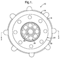
- Pump 10 generally indicates a radial piston fuel pump according to the invention.
- Pump 10 includes a stationary body 12 having an end portion 14 sealingly mounted to an enclosing housing 16.
- the housing includes a flared portion 18 defining a circular enclosure 20 and a flanged extension 22 defining a mounting portion.
- the housing 16 rotatably supports a cam member 24 having a drive shaft 26 supported by a ball bearing 28 carried adjacent a mounting flange 30 on the extension 22.
- the drive shaft connects with a radial disk 32 supporting a cam ring 34 for rotation within the enclosure 20.
- a mechanical fuel seal 35 sealingly engages the disk 32 adjacent to the drive shaft 26.
- the interior of the ring 34 is provided with four equiangularly spaced inwardly raised cam lobes 36 that extend inward from the otherwise circular inner surface 38 of the ring 34.
- the cam lobes are shown as flat surfaces but may be made with any desired configuration suitable for their subsequently described purpose.
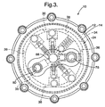
- a generally cylindrical portion 40 of the body 12 extends into the cam ring 34 within the circular enclosure 20 of the housing 16.
- a plurality of radial bores or cylinders are provided within the cylindrical portion 40. These include two pairs of pumping cylinders including two radially aligned small cylinders 42 and two radially aligned larger cylinders 44. The smaller cylinders are positioned at predetermined angles ahead of the larger cylinders in the direction of rotation of the cam ring (clockwise as shown in FIG. 4) to form related pairs of cooperating small and larger cylinders, which provide pressure pulse damping in a manner to be subsequently made clear.
- plungers 46, 48 are reciprocably received.
- the plungers are biased outward by springs 50, 52 to engage cam followers including follower shoes 54 and follower rollers 56.
- the shoes 54 are received in follower slots or recesses 58 in the body 12 and the follower rollers 56 are carried for rotation in the shoes 54.
- Springs 60 urge the shoes outward to maintain the rollers against the interior surface of the cam ring 34.
- the interiors of the plungers are hollow to provide for radial inflow of excess fuel from the follower recesses.
- Ball check valves 62 are provided to prevent backflow of the fuel outward through the plungers.
- the cylinders 42, 44 are open at their inner ends to an axially extending central fuel chamber 64 into which fuel is drawn through an inlet port 66 in the end portion 14 of the stationary body 12.
- a valve such as a spring loaded inlet check valve 68 prevents return fuel flow out of the port 66.
- Additional radial bores connecting with the central fuel chamber include an outlet passage 70, a spill passage 72 and an internal relief passage 74.
- the outlet passage 70 includes an outlet check valve 76 for preventing fuel return inflow and connects with an outlet port 78 opening axially through the body end portion 14 for connection to a fuel distribution line, not shown.
- the spill passage 72 connects with a spill port 80 opening axially through end portion 14 for connection with an external pressure control valve, not shown, to control fuel outlet pressure.
- the internal relief passage 74 includes a spring loaded pressure relief valve 82 that opens to relieve excessive fuel pressure through an open outer end of the passage 74 to a clearance volume 84 surrounding the cylindrical portion 40 of the body 12. High fuel pressure in this clearance volume may be relieved by return fuel flow through the plungers 46, 48 to the central fuel chamber 64.
- the cam ring 34 is directly supported by a journal sleeve 86 mounted on the cam ring and engaging an internal bearing sleeve 88 mounted in the housing 16 of the body 12.
- These bearing sleeves are preferably made of a hard wear resistant material, such as tungsten carbide, to provide long wear in spite of the poor lubricating characteristics of the gasoline fuel pressurized by the pump.
- the drive shaft 26 is driven by an external power source, such as the engine crankshaft, not shown.
- the shaft rotates the cam ring 34 clockwise in the direction of arrow 90 as shown in FIG. 4.
- the inwardly raised cam lobes 36 sequentially engage first the cam follower rollers 56 of the smaller plungers 46 and second the rollers 56 of the larger plungers 48.
- the smaller plungers are first moved inward, forcing an initial volume of fuel from the fuel chamber 64 through the outlet port 78.
- the larger plungers are actuated inward forcing a larger volume of fuel from chamber 64 through the outlet port 78.
- the overlapping fuel pulses provide an increasing flow rate for each pulse of fuel, so that the shock waves initiated by the fuel pulses are moderated.
- the plungers are each actuated four times for every revolution of the cam member.
- the pump discharges four moderated sequential fuel pulses from both pairs of smaller and larger plungers with each turn of the pump drive shaft.
- the normal fuel outlet pressure of the pump may be controlled by an external pressure regulator connected to the outlet of the pump or by means of an electronically controlled spill valve, not shown, connected to the optional spill port 80, which ports fuel directly from the cylinder volume, bypassing the inlet and outlet valves.
- a spill valve connected to the port 80, and additionally to the inlet supply line, thus provides a means for a variable volume of fuel to bypass the pumping event and pass through the spill valve to the inlet side of the pump. Functioning effectively as a variable displacement pump, a net energy savings can be realized.
- Implementation of a spill valve pressure control system would normally include a pressure feedback loop and may also require pump-cylinder position reference.
- the internal pressure relief valve opens and discharges fuel into the clearance volume 84 within the cam ring 34 to reduce the pressure. If pressure build-up in the clearance volume 84 occurs, it is relieved by fuel flow through the plungers and back to the central fuel chamber 64.
- the shaft seal 35 acts to prevent loss of fuel through leakage past the drive shaft 26.
- numeral 92 indicates a pump comprising an alternative embodiment of the invention wherein like numerals indicate components like those of the first embodiment.
- Pump 92 differs from pump 10 by the omission of the two smaller cylinders and plungers from the body 92 and by rearrangement of the radial bores.
- body 94 includes two larger cylinders 44 with plungers 48 aligned radially opposite one another.
- An outlet passage 70, spill passage 72 and relief passage 74 are also included as are a central fuel chamber 64 and an outlet port, not shown.
- pump 92 is simplified by omission of the smaller cylinders, its operation is subject to increased pressure pulsations without the modulation from the more gradual pressure build-up provided by the smaller cylinders.
- the pumps provide efficient high pressure output in a compact unit with a minimum of external leakage and with fuel connections limited to inlet and outlet ports in the housing end portion.
Landscapes
- Engineering & Computer Science (AREA)
- Chemical & Material Sciences (AREA)
- Combustion & Propulsion (AREA)
- Mechanical Engineering (AREA)
- General Engineering & Computer Science (AREA)
- Fuel-Injection Apparatus (AREA)
- Lubrication Of Internal Combustion Engines (AREA)
- Details Of Reciprocating Pumps (AREA)
- Reciprocating Pumps (AREA)
Applications Claiming Priority (2)
| Application Number | Priority Date | Filing Date | Title |
|---|---|---|---|
| US457273 | 2003-06-09 | ||
| US10/457,273 US7048516B2 (en) | 2003-06-09 | 2003-06-09 | High pressure fuel pump with multiple radial plungers |
Publications (2)
| Publication Number | Publication Date |
|---|---|
| EP1486664A1 true EP1486664A1 (fr) | 2004-12-15 |
| EP1486664B1 EP1486664B1 (fr) | 2007-05-02 |
Family
ID=33299618
Family Applications (1)
| Application Number | Title | Priority Date | Filing Date |
|---|---|---|---|
| EP04076666A Not-in-force EP1486664B1 (fr) | 2003-06-09 | 2004-06-07 | Pompe à haute pression avec plusieurs pistons radiaux |
Country Status (4)
| Country | Link |
|---|---|
| US (1) | US7048516B2 (fr) |
| EP (1) | EP1486664B1 (fr) |
| AT (1) | ATE361417T1 (fr) |
| DE (1) | DE602004006194T2 (fr) |
Cited By (1)
| Publication number | Priority date | Publication date | Assignee | Title |
|---|---|---|---|---|
| WO2020035627A1 (fr) * | 2018-08-14 | 2020-02-20 | Rotary Wave, S.L. | Motopompe pour l'exploitation de l'énergie d'une ou de plusieurs sources énergétiques à puissance constante ou variable, pour pomper des fluides à pression constante préréglée et pour la production d'électricité |
Families Citing this family (4)
| Publication number | Priority date | Publication date | Assignee | Title |
|---|---|---|---|---|
| DE102004058726A1 (de) * | 2004-12-06 | 2006-06-08 | Lucas Automotive Gmbh | Druckerzeuger für eine Fahrzeugbremsanlage und Montageverfahren für den Druckerzeuger |
| JP4670844B2 (ja) * | 2007-07-19 | 2011-04-13 | トヨタ自動車株式会社 | 油圧装置 |
| GB201202221D0 (en) * | 2012-02-09 | 2012-03-28 | Delphi Tech Holding Sarl | Improvements relating to fuel pumps |
| RU2610333C1 (ru) * | 2015-10-07 | 2017-02-09 | Ольга Иосифовна Логинова | Радиально-плунжерный насос |
Citations (3)
| Publication number | Priority date | Publication date | Assignee | Title |
|---|---|---|---|---|
| US5318001A (en) * | 1991-12-05 | 1994-06-07 | Stanadyne Automotive Corp. | Distributor type fuel injection pump |
| USRE37632E1 (en) * | 1995-11-29 | 2002-04-09 | Delphi Technologies Inc. | Fuel pump |
| DE10115167C1 (de) * | 2001-03-27 | 2002-12-12 | Orange Gmbh | Radialkolben-Hochdruckpumpe, insbesondere für Einspritzsysteme von Brennkraftmaschinen |
Family Cites Families (11)
| Publication number | Priority date | Publication date | Assignee | Title |
|---|---|---|---|---|
| FR1384096A (fr) * | 1963-11-21 | 1965-01-04 | Sigma | Perfectionnements apportés aux pompes d'injection à distributeur pour moteurs à cinq cylindres |
| US4846631A (en) * | 1986-11-19 | 1989-07-11 | Minnovation Limited | Gearbox for a rotary, mineral cutting head |
| DE3816508A1 (de) * | 1988-05-14 | 1989-11-23 | Bosch Gmbh Robert | Kraftstoffeinspritzpumpe fuer brennkraftmaschine |
| DE3919456A1 (de) * | 1989-06-14 | 1990-12-20 | Rexroth Mannesmann Gmbh | Radialkolbenmotor |
| US5228844A (en) * | 1992-10-14 | 1993-07-20 | Stanadyne Automotive Corp. | Rotary distributor type fuel injection pump |
| DE4338344A1 (de) * | 1993-11-10 | 1995-05-11 | Bosch Gmbh Robert | Verteilerkraftstoffeinspritzpumpe für Brennkraftmaschinen |
| JPH08246978A (ja) * | 1995-03-13 | 1996-09-24 | Zexel Corp | 内面カム式噴射ポンプ |
| DE19640678A1 (de) * | 1996-10-02 | 1998-04-09 | Bosch Gmbh Robert | Kraftstoffeinspritzpumpe mit einem der Spritzbeginnverstellung dienenden Spritzverstellkolben |
| GB9810327D0 (en) * | 1998-05-15 | 1998-07-15 | Lucas Ind Plc | Fuel system and pump suitable for use therein |
| IT1306266B1 (it) * | 1998-07-24 | 2001-06-04 | Gd Spa | Metodo di controllo di un oggetto stampato |
| GB9920200D0 (en) | 1999-08-27 | 1999-10-27 | Lucas Ind Plc | Fuel pump |
-
2003
- 2003-06-09 US US10/457,273 patent/US7048516B2/en not_active Expired - Fee Related
-
2004
- 2004-06-07 EP EP04076666A patent/EP1486664B1/fr not_active Not-in-force
- 2004-06-07 AT AT04076666T patent/ATE361417T1/de not_active IP Right Cessation
- 2004-06-07 DE DE602004006194T patent/DE602004006194T2/de active Active
Patent Citations (3)
| Publication number | Priority date | Publication date | Assignee | Title |
|---|---|---|---|---|
| US5318001A (en) * | 1991-12-05 | 1994-06-07 | Stanadyne Automotive Corp. | Distributor type fuel injection pump |
| USRE37632E1 (en) * | 1995-11-29 | 2002-04-09 | Delphi Technologies Inc. | Fuel pump |
| DE10115167C1 (de) * | 2001-03-27 | 2002-12-12 | Orange Gmbh | Radialkolben-Hochdruckpumpe, insbesondere für Einspritzsysteme von Brennkraftmaschinen |
Cited By (1)
| Publication number | Priority date | Publication date | Assignee | Title |
|---|---|---|---|---|
| WO2020035627A1 (fr) * | 2018-08-14 | 2020-02-20 | Rotary Wave, S.L. | Motopompe pour l'exploitation de l'énergie d'une ou de plusieurs sources énergétiques à puissance constante ou variable, pour pomper des fluides à pression constante préréglée et pour la production d'électricité |
Also Published As
| Publication number | Publication date |
|---|---|
| DE602004006194D1 (de) | 2007-06-14 |
| ATE361417T1 (de) | 2007-05-15 |
| DE602004006194T2 (de) | 2007-08-30 |
| EP1486664B1 (fr) | 2007-05-02 |
| US20040247470A1 (en) | 2004-12-09 |
| US7048516B2 (en) | 2006-05-23 |
Similar Documents
| Publication | Publication Date | Title |
|---|---|---|
| US5984650A (en) | Pressure fuel pump device | |
| US6722857B1 (en) | Pump assembly for fuel | |
| US10240525B2 (en) | Variable compression ratio connecting rod system with rotary actuator | |
| JP2010229924A (ja) | 高圧ポンプ | |
| JP2010229914A (ja) | 高圧ポンプ | |
| US6497216B2 (en) | Pump for supplying a fuel injection system and for supplying a hydraulic valve controller for internal combustion engines | |
| EP0972936A2 (fr) | Pompes volumétriques | |
| US8162632B2 (en) | Fluid pump | |
| EP1486664B1 (fr) | Pompe à haute pression avec plusieurs pistons radiaux | |
| EP1076180B1 (fr) | Pompe à carburant | |
| US4879984A (en) | Fuel injection pump for internal combustion engines | |
| JP4461026B2 (ja) | 内燃機関のための燃料噴射装置 | |
| KR20100042646A (ko) | 펌프, 특히 고압 연료 펌프 | |
| JP2003328896A (ja) | 内燃機関のための燃料ポンプ | |
| EP1484504A1 (fr) | Appareil d'alimentation en carburant | |
| JP5412570B2 (ja) | ターボ過給式大型2ストロークディーゼルエンジンのための燃料ポンプ | |
| US5383436A (en) | Fuel injection pump for internal combustion engines | |
| US6582203B2 (en) | Radial piston pump | |
| EP0821156A3 (fr) | Pompe de carburant | |
| JP2965032B1 (ja) | 内燃機関の燃料ポンプ | |
| EP0966597A1 (fr) | Pompe hydraulique a palier d'entrainement monte sur un moteur | |
| JPH05215032A (ja) | 内燃機関に用いられる燃料噴射ポンプ | |
| JPH10184494A (ja) | 内燃機関の燃料加圧ポンプ | |
| US6364631B1 (en) | Pump apparatus for hydraulically powered fuel injection systems | |
| JP2619727B2 (ja) | 低粘性燃料油用ラジアルピストンポンプ |
Legal Events
| Date | Code | Title | Description |
|---|---|---|---|
| PUAI | Public reference made under article 153(3) epc to a published international application that has entered the european phase |
Free format text: ORIGINAL CODE: 0009012 |
|
| AK | Designated contracting states |
Kind code of ref document: A1 Designated state(s): AT BE BG CH CY CZ DE DK EE ES FI FR GB GR HU IE IT LI LU MC NL PL PT RO SE SI SK TR |
|
| AX | Request for extension of the european patent |
Extension state: AL HR LT LV MK |
|
| 17P | Request for examination filed |
Effective date: 20050615 |
|
| AKX | Designation fees paid |
Designated state(s): AT BE BG CH CY CZ DE DK EE ES FI FR GB GR HU IE IT LI LU MC NL PL PT RO SE SI SK TR |
|
| GRAP | Despatch of communication of intention to grant a patent |
Free format text: ORIGINAL CODE: EPIDOSNIGR1 |
|
| GRAS | Grant fee paid |
Free format text: ORIGINAL CODE: EPIDOSNIGR3 |
|
| GRAA | (expected) grant |
Free format text: ORIGINAL CODE: 0009210 |
|
| AK | Designated contracting states |
Kind code of ref document: B1 Designated state(s): AT BE BG CH CY CZ DE DK EE ES FI FR GB GR HU IE IT LI LU MC NL PL PT RO SE SI SK TR |
|
| PG25 | Lapsed in a contracting state [announced via postgrant information from national office to epo] |
Ref country code: LI Free format text: LAPSE BECAUSE OF FAILURE TO SUBMIT A TRANSLATION OF THE DESCRIPTION OR TO PAY THE FEE WITHIN THE PRESCRIBED TIME-LIMIT Effective date: 20070502 Ref country code: CH Free format text: LAPSE BECAUSE OF FAILURE TO SUBMIT A TRANSLATION OF THE DESCRIPTION OR TO PAY THE FEE WITHIN THE PRESCRIBED TIME-LIMIT Effective date: 20070502 Ref country code: FI Free format text: LAPSE BECAUSE OF FAILURE TO SUBMIT A TRANSLATION OF THE DESCRIPTION OR TO PAY THE FEE WITHIN THE PRESCRIBED TIME-LIMIT Effective date: 20070502 |
|
| REG | Reference to a national code |
Ref country code: GB Ref legal event code: FG4D |
|
| REG | Reference to a national code |
Ref country code: CH Ref legal event code: EP |
|
| REG | Reference to a national code |
Ref country code: IE Ref legal event code: FG4D |
|
| REF | Corresponds to: |
Ref document number: 602004006194 Country of ref document: DE Date of ref document: 20070614 Kind code of ref document: P |
|
| PG25 | Lapsed in a contracting state [announced via postgrant information from national office to epo] |
Ref country code: SE Free format text: LAPSE BECAUSE OF FAILURE TO SUBMIT A TRANSLATION OF THE DESCRIPTION OR TO PAY THE FEE WITHIN THE PRESCRIBED TIME-LIMIT Effective date: 20070802 |
|
| PG25 | Lapsed in a contracting state [announced via postgrant information from national office to epo] |
Ref country code: ES Free format text: LAPSE BECAUSE OF FAILURE TO SUBMIT A TRANSLATION OF THE DESCRIPTION OR TO PAY THE FEE WITHIN THE PRESCRIBED TIME-LIMIT Effective date: 20070813 |
|
| ET | Fr: translation filed | ||
| NLV1 | Nl: lapsed or annulled due to failure to fulfill the requirements of art. 29p and 29m of the patents act | ||
| REG | Reference to a national code |
Ref country code: CH Ref legal event code: PL |
|
| PG25 | Lapsed in a contracting state [announced via postgrant information from national office to epo] |
Ref country code: AT Free format text: LAPSE BECAUSE OF FAILURE TO SUBMIT A TRANSLATION OF THE DESCRIPTION OR TO PAY THE FEE WITHIN THE PRESCRIBED TIME-LIMIT Effective date: 20070502 Ref country code: PL Free format text: LAPSE BECAUSE OF FAILURE TO SUBMIT A TRANSLATION OF THE DESCRIPTION OR TO PAY THE FEE WITHIN THE PRESCRIBED TIME-LIMIT Effective date: 20070502 |
|
| PG25 | Lapsed in a contracting state [announced via postgrant information from national office to epo] |
Ref country code: BE Free format text: LAPSE BECAUSE OF FAILURE TO SUBMIT A TRANSLATION OF THE DESCRIPTION OR TO PAY THE FEE WITHIN THE PRESCRIBED TIME-LIMIT Effective date: 20070502 |
|
| PG25 | Lapsed in a contracting state [announced via postgrant information from national office to epo] |
Ref country code: SI Free format text: LAPSE BECAUSE OF FAILURE TO SUBMIT A TRANSLATION OF THE DESCRIPTION OR TO PAY THE FEE WITHIN THE PRESCRIBED TIME-LIMIT Effective date: 20070502 Ref country code: PT Free format text: LAPSE BECAUSE OF FAILURE TO SUBMIT A TRANSLATION OF THE DESCRIPTION OR TO PAY THE FEE WITHIN THE PRESCRIBED TIME-LIMIT Effective date: 20071002 Ref country code: BG Free format text: LAPSE BECAUSE OF FAILURE TO SUBMIT A TRANSLATION OF THE DESCRIPTION OR TO PAY THE FEE WITHIN THE PRESCRIBED TIME-LIMIT Effective date: 20070802 Ref country code: NL Free format text: LAPSE BECAUSE OF FAILURE TO SUBMIT A TRANSLATION OF THE DESCRIPTION OR TO PAY THE FEE WITHIN THE PRESCRIBED TIME-LIMIT Effective date: 20070502 Ref country code: CZ Free format text: LAPSE BECAUSE OF FAILURE TO SUBMIT A TRANSLATION OF THE DESCRIPTION OR TO PAY THE FEE WITHIN THE PRESCRIBED TIME-LIMIT Effective date: 20070502 Ref country code: MC Free format text: LAPSE BECAUSE OF NON-PAYMENT OF DUE FEES Effective date: 20070630 Ref country code: DK Free format text: LAPSE BECAUSE OF FAILURE TO SUBMIT A TRANSLATION OF THE DESCRIPTION OR TO PAY THE FEE WITHIN THE PRESCRIBED TIME-LIMIT Effective date: 20070502 |
|
| PG25 | Lapsed in a contracting state [announced via postgrant information from national office to epo] |
Ref country code: SK Free format text: LAPSE BECAUSE OF FAILURE TO SUBMIT A TRANSLATION OF THE DESCRIPTION OR TO PAY THE FEE WITHIN THE PRESCRIBED TIME-LIMIT Effective date: 20070502 |
|
| PLBE | No opposition filed within time limit |
Free format text: ORIGINAL CODE: 0009261 |
|
| STAA | Information on the status of an ep patent application or granted ep patent |
Free format text: STATUS: NO OPPOSITION FILED WITHIN TIME LIMIT |
|
| 26N | No opposition filed |
Effective date: 20080205 |
|
| PG25 | Lapsed in a contracting state [announced via postgrant information from national office to epo] |
Ref country code: GR Free format text: LAPSE BECAUSE OF FAILURE TO SUBMIT A TRANSLATION OF THE DESCRIPTION OR TO PAY THE FEE WITHIN THE PRESCRIBED TIME-LIMIT Effective date: 20070803 Ref country code: IT Free format text: LAPSE BECAUSE OF FAILURE TO SUBMIT A TRANSLATION OF THE DESCRIPTION OR TO PAY THE FEE WITHIN THE PRESCRIBED TIME-LIMIT Effective date: 20070502 |
|
| PG25 | Lapsed in a contracting state [announced via postgrant information from national office to epo] |
Ref country code: IE Free format text: LAPSE BECAUSE OF NON-PAYMENT OF DUE FEES Effective date: 20070607 Ref country code: RO Free format text: LAPSE BECAUSE OF FAILURE TO SUBMIT A TRANSLATION OF THE DESCRIPTION OR TO PAY THE FEE WITHIN THE PRESCRIBED TIME-LIMIT Effective date: 20070502 |
|
| PG25 | Lapsed in a contracting state [announced via postgrant information from national office to epo] |
Ref country code: EE Free format text: LAPSE BECAUSE OF FAILURE TO SUBMIT A TRANSLATION OF THE DESCRIPTION OR TO PAY THE FEE WITHIN THE PRESCRIBED TIME-LIMIT Effective date: 20070502 |
|
| GBPC | Gb: european patent ceased through non-payment of renewal fee |
Effective date: 20080607 |
|
| PG25 | Lapsed in a contracting state [announced via postgrant information from national office to epo] |
Ref country code: GB Free format text: LAPSE BECAUSE OF NON-PAYMENT OF DUE FEES Effective date: 20080607 |
|
| PG25 | Lapsed in a contracting state [announced via postgrant information from national office to epo] |
Ref country code: CY Free format text: LAPSE BECAUSE OF FAILURE TO SUBMIT A TRANSLATION OF THE DESCRIPTION OR TO PAY THE FEE WITHIN THE PRESCRIBED TIME-LIMIT Effective date: 20070502 |
|
| PG25 | Lapsed in a contracting state [announced via postgrant information from national office to epo] |
Ref country code: LU Free format text: LAPSE BECAUSE OF NON-PAYMENT OF DUE FEES Effective date: 20070607 |
|
| PG25 | Lapsed in a contracting state [announced via postgrant information from national office to epo] |
Ref country code: HU Free format text: LAPSE BECAUSE OF FAILURE TO SUBMIT A TRANSLATION OF THE DESCRIPTION OR TO PAY THE FEE WITHIN THE PRESCRIBED TIME-LIMIT Effective date: 20071103 Ref country code: TR Free format text: LAPSE BECAUSE OF FAILURE TO SUBMIT A TRANSLATION OF THE DESCRIPTION OR TO PAY THE FEE WITHIN THE PRESCRIBED TIME-LIMIT Effective date: 20070502 |
|
| PGFP | Annual fee paid to national office [announced via postgrant information from national office to epo] |
Ref country code: FR Payment date: 20100709 Year of fee payment: 7 |
|
| PGFP | Annual fee paid to national office [announced via postgrant information from national office to epo] |
Ref country code: DE Payment date: 20100602 Year of fee payment: 7 |
|
| REG | Reference to a national code |
Ref country code: FR Ref legal event code: ST Effective date: 20120229 |
|
| REG | Reference to a national code |
Ref country code: DE Ref legal event code: R119 Ref document number: 602004006194 Country of ref document: DE Effective date: 20120103 |
|
| PG25 | Lapsed in a contracting state [announced via postgrant information from national office to epo] |
Ref country code: DE Free format text: LAPSE BECAUSE OF NON-PAYMENT OF DUE FEES Effective date: 20120103 Ref country code: FR Free format text: LAPSE BECAUSE OF NON-PAYMENT OF DUE FEES Effective date: 20110630 |