EP1486584A2 - Verfahren zum Auftragen einer Sperrbeschichtung auf ein Kunststoffsubstrat - Google Patents
Verfahren zum Auftragen einer Sperrbeschichtung auf ein Kunststoffsubstrat Download PDFInfo
- Publication number
- EP1486584A2 EP1486584A2 EP04021084A EP04021084A EP1486584A2 EP 1486584 A2 EP1486584 A2 EP 1486584A2 EP 04021084 A EP04021084 A EP 04021084A EP 04021084 A EP04021084 A EP 04021084A EP 1486584 A2 EP1486584 A2 EP 1486584A2
- Authority
- EP
- European Patent Office
- Prior art keywords
- layer
- tube
- coating
- plasma
- container
- Prior art date
- Legal status (The legal status is an assumption and is not a legal conclusion. Google has not performed a legal analysis and makes no representation as to the accuracy of the status listed.)
- Granted
Links
Images


Classifications
-
- B—PERFORMING OPERATIONS; TRANSPORTING
- B01—PHYSICAL OR CHEMICAL PROCESSES OR APPARATUS IN GENERAL
- B01L—CHEMICAL OR PHYSICAL LABORATORY APPARATUS FOR GENERAL USE
- B01L3/00—Containers or dishes for laboratory use, e.g. laboratory glassware; Droppers
- B01L3/50—Containers for the purpose of retaining a material to be analysed, e.g. test tubes
- B01L3/502—Containers for the purpose of retaining a material to be analysed, e.g. test tubes with fluid transport, e.g. in multi-compartment structures
- B01L3/5021—Test tubes specially adapted for centrifugation purposes
-
- A—HUMAN NECESSITIES
- A61—MEDICAL OR VETERINARY SCIENCE; HYGIENE
- A61J—CONTAINERS SPECIALLY ADAPTED FOR MEDICAL OR PHARMACEUTICAL PURPOSES; DEVICES OR METHODS SPECIALLY ADAPTED FOR BRINGING PHARMACEUTICAL PRODUCTS INTO PARTICULAR PHYSICAL OR ADMINISTERING FORMS; DEVICES FOR ADMINISTERING FOOD OR MEDICINES ORALLY; BABY COMFORTERS; DEVICES FOR RECEIVING SPITTLE
- A61J1/00—Containers specially adapted for medical or pharmaceutical purposes
- A61J1/05—Containers specially adapted for medical or pharmaceutical purposes for collecting, storing or administering blood, plasma or medical fluids ; Infusion or perfusion containers
-
- B—PERFORMING OPERATIONS; TRANSPORTING
- B01—PHYSICAL OR CHEMICAL PROCESSES OR APPARATUS IN GENERAL
- B01L—CHEMICAL OR PHYSICAL LABORATORY APPARATUS FOR GENERAL USE
- B01L3/00—Containers or dishes for laboratory use, e.g. laboratory glassware; Droppers
- B01L3/50—Containers for the purpose of retaining a material to be analysed, e.g. test tubes
- B01L3/508—Containers for the purpose of retaining a material to be analysed, e.g. test tubes rigid containers not provided for above
- B01L3/5082—Test tubes per se
-
- B—PERFORMING OPERATIONS; TRANSPORTING
- B05—SPRAYING OR ATOMISING IN GENERAL; APPLYING FLUENT MATERIALS TO SURFACES, IN GENERAL
- B05D—PROCESSES FOR APPLYING FLUENT MATERIALS TO SURFACES, IN GENERAL
- B05D1/00—Processes for applying liquids or other fluent materials
- B05D1/60—Deposition of organic layers from vapour phase
-
- B—PERFORMING OPERATIONS; TRANSPORTING
- B05—SPRAYING OR ATOMISING IN GENERAL; APPLYING FLUENT MATERIALS TO SURFACES, IN GENERAL
- B05D—PROCESSES FOR APPLYING FLUENT MATERIALS TO SURFACES, IN GENERAL
- B05D7/00—Processes, other than flocking, specially adapted for applying liquids or other fluent materials to particular surfaces or for applying particular liquids or other fluent materials
- B05D7/02—Processes, other than flocking, specially adapted for applying liquids or other fluent materials to particular surfaces or for applying particular liquids or other fluent materials to macromolecular substances, e.g. rubber
-
- C—CHEMISTRY; METALLURGY
- C08—ORGANIC MACROMOLECULAR COMPOUNDS; THEIR PREPARATION OR CHEMICAL WORKING-UP; COMPOSITIONS BASED THEREON
- C08J—WORKING-UP; GENERAL PROCESSES OF COMPOUNDING; AFTER-TREATMENT NOT COVERED BY SUBCLASSES C08B, C08C, C08F, C08G or C08H
- C08J7/00—Chemical treatment or coating of shaped articles made of macromolecular substances
- C08J7/04—Coating
- C08J7/042—Coating with two or more layers, where at least one layer of a composition contains a polymer binder
- C08J7/0423—Coating with two or more layers, where at least one layer of a composition contains a polymer binder with at least one layer of inorganic material and at least one layer of a composition containing a polymer binder
-
- C—CHEMISTRY; METALLURGY
- C08—ORGANIC MACROMOLECULAR COMPOUNDS; THEIR PREPARATION OR CHEMICAL WORKING-UP; COMPOSITIONS BASED THEREON
- C08J—WORKING-UP; GENERAL PROCESSES OF COMPOUNDING; AFTER-TREATMENT NOT COVERED BY SUBCLASSES C08B, C08C, C08F, C08G or C08H
- C08J7/00—Chemical treatment or coating of shaped articles made of macromolecular substances
- C08J7/04—Coating
- C08J7/0427—Coating with only one layer of a composition containing a polymer binder
-
- C—CHEMISTRY; METALLURGY
- C08—ORGANIC MACROMOLECULAR COMPOUNDS; THEIR PREPARATION OR CHEMICAL WORKING-UP; COMPOSITIONS BASED THEREON
- C08J—WORKING-UP; GENERAL PROCESSES OF COMPOUNDING; AFTER-TREATMENT NOT COVERED BY SUBCLASSES C08B, C08C, C08F, C08G or C08H
- C08J7/00—Chemical treatment or coating of shaped articles made of macromolecular substances
- C08J7/04—Coating
- C08J7/043—Improving the adhesiveness of the coatings per se, e.g. forming primers
-
- C—CHEMISTRY; METALLURGY
- C08—ORGANIC MACROMOLECULAR COMPOUNDS; THEIR PREPARATION OR CHEMICAL WORKING-UP; COMPOSITIONS BASED THEREON
- C08J—WORKING-UP; GENERAL PROCESSES OF COMPOUNDING; AFTER-TREATMENT NOT COVERED BY SUBCLASSES C08B, C08C, C08F, C08G or C08H
- C08J7/00—Chemical treatment or coating of shaped articles made of macromolecular substances
- C08J7/04—Coating
- C08J7/046—Forming abrasion-resistant coatings; Forming surface-hardening coatings
-
- C—CHEMISTRY; METALLURGY
- C08—ORGANIC MACROMOLECULAR COMPOUNDS; THEIR PREPARATION OR CHEMICAL WORKING-UP; COMPOSITIONS BASED THEREON
- C08J—WORKING-UP; GENERAL PROCESSES OF COMPOUNDING; AFTER-TREATMENT NOT COVERED BY SUBCLASSES C08B, C08C, C08F, C08G or C08H
- C08J7/00—Chemical treatment or coating of shaped articles made of macromolecular substances
- C08J7/04—Coating
- C08J7/048—Forming gas barrier coatings
-
- C—CHEMISTRY; METALLURGY
- C08—ORGANIC MACROMOLECULAR COMPOUNDS; THEIR PREPARATION OR CHEMICAL WORKING-UP; COMPOSITIONS BASED THEREON
- C08J—WORKING-UP; GENERAL PROCESSES OF COMPOUNDING; AFTER-TREATMENT NOT COVERED BY SUBCLASSES C08B, C08C, C08F, C08G or C08H
- C08J7/00—Chemical treatment or coating of shaped articles made of macromolecular substances
- C08J7/12—Chemical modification
- C08J7/123—Treatment by wave energy or particle radiation
-
- C—CHEMISTRY; METALLURGY
- C23—COATING METALLIC MATERIAL; COATING MATERIAL WITH METALLIC MATERIAL; CHEMICAL SURFACE TREATMENT; DIFFUSION TREATMENT OF METALLIC MATERIAL; COATING BY VACUUM EVAPORATION, BY SPUTTERING, BY ION IMPLANTATION OR BY CHEMICAL VAPOUR DEPOSITION, IN GENERAL; INHIBITING CORROSION OF METALLIC MATERIAL OR INCRUSTATION IN GENERAL
- C23C—COATING METALLIC MATERIAL; COATING MATERIAL WITH METALLIC MATERIAL; SURFACE TREATMENT OF METALLIC MATERIAL BY DIFFUSION INTO THE SURFACE, BY CHEMICAL CONVERSION OR SUBSTITUTION; COATING BY VACUUM EVAPORATION, BY SPUTTERING, BY ION IMPLANTATION OR BY CHEMICAL VAPOUR DEPOSITION, IN GENERAL
- C23C16/00—Chemical coating by decomposition of gaseous compounds, without leaving reaction products of surface material in the coating, i.e. chemical vapour deposition [CVD] processes
- C23C16/02—Pretreatment of the material to be coated
- C23C16/0227—Pretreatment of the material to be coated by cleaning or etching
- C23C16/0245—Pretreatment of the material to be coated by cleaning or etching by etching with a plasma
-
- C—CHEMISTRY; METALLURGY
- C23—COATING METALLIC MATERIAL; COATING MATERIAL WITH METALLIC MATERIAL; CHEMICAL SURFACE TREATMENT; DIFFUSION TREATMENT OF METALLIC MATERIAL; COATING BY VACUUM EVAPORATION, BY SPUTTERING, BY ION IMPLANTATION OR BY CHEMICAL VAPOUR DEPOSITION, IN GENERAL; INHIBITING CORROSION OF METALLIC MATERIAL OR INCRUSTATION IN GENERAL
- C23C—COATING METALLIC MATERIAL; COATING MATERIAL WITH METALLIC MATERIAL; SURFACE TREATMENT OF METALLIC MATERIAL BY DIFFUSION INTO THE SURFACE, BY CHEMICAL CONVERSION OR SUBSTITUTION; COATING BY VACUUM EVAPORATION, BY SPUTTERING, BY ION IMPLANTATION OR BY CHEMICAL VAPOUR DEPOSITION, IN GENERAL
- C23C16/00—Chemical coating by decomposition of gaseous compounds, without leaving reaction products of surface material in the coating, i.e. chemical vapour deposition [CVD] processes
- C23C16/04—Coating on selected surface areas, e.g. using masks
- C23C16/045—Coating cavities or hollow spaces, e.g. interior of tubes; Infiltration of porous substrates
-
- C—CHEMISTRY; METALLURGY
- C23—COATING METALLIC MATERIAL; COATING MATERIAL WITH METALLIC MATERIAL; CHEMICAL SURFACE TREATMENT; DIFFUSION TREATMENT OF METALLIC MATERIAL; COATING BY VACUUM EVAPORATION, BY SPUTTERING, BY ION IMPLANTATION OR BY CHEMICAL VAPOUR DEPOSITION, IN GENERAL; INHIBITING CORROSION OF METALLIC MATERIAL OR INCRUSTATION IN GENERAL
- C23C—COATING METALLIC MATERIAL; COATING MATERIAL WITH METALLIC MATERIAL; SURFACE TREATMENT OF METALLIC MATERIAL BY DIFFUSION INTO THE SURFACE, BY CHEMICAL CONVERSION OR SUBSTITUTION; COATING BY VACUUM EVAPORATION, BY SPUTTERING, BY ION IMPLANTATION OR BY CHEMICAL VAPOUR DEPOSITION, IN GENERAL
- C23C16/00—Chemical coating by decomposition of gaseous compounds, without leaving reaction products of surface material in the coating, i.e. chemical vapour deposition [CVD] processes
- C23C16/22—Chemical coating by decomposition of gaseous compounds, without leaving reaction products of surface material in the coating, i.e. chemical vapour deposition [CVD] processes characterised by the deposition of inorganic material, other than metallic material
- C23C16/30—Deposition of compounds, mixtures or solid solutions, e.g. borides, carbides, nitrides
- C23C16/40—Oxides
- C23C16/401—Oxides containing silicon
-
- B—PERFORMING OPERATIONS; TRANSPORTING
- B01—PHYSICAL OR CHEMICAL PROCESSES OR APPARATUS IN GENERAL
- B01L—CHEMICAL OR PHYSICAL LABORATORY APPARATUS FOR GENERAL USE
- B01L2200/00—Solutions for specific problems relating to chemical or physical laboratory apparatus
- B01L2200/12—Specific details about manufacturing devices
-
- B—PERFORMING OPERATIONS; TRANSPORTING
- B01—PHYSICAL OR CHEMICAL PROCESSES OR APPARATUS IN GENERAL
- B01L—CHEMICAL OR PHYSICAL LABORATORY APPARATUS FOR GENERAL USE
- B01L2200/00—Solutions for specific problems relating to chemical or physical laboratory apparatus
- B01L2200/14—Process control and prevention of errors
- B01L2200/142—Preventing evaporation
-
- B—PERFORMING OPERATIONS; TRANSPORTING
- B01—PHYSICAL OR CHEMICAL PROCESSES OR APPARATUS IN GENERAL
- B01L—CHEMICAL OR PHYSICAL LABORATORY APPARATUS FOR GENERAL USE
- B01L2300/00—Additional constructional details
- B01L2300/04—Closures and closing means
- B01L2300/041—Connecting closures to device or container
- B01L2300/042—Caps; Plugs
-
- B—PERFORMING OPERATIONS; TRANSPORTING
- B01—PHYSICAL OR CHEMICAL PROCESSES OR APPARATUS IN GENERAL
- B01L—CHEMICAL OR PHYSICAL LABORATORY APPARATUS FOR GENERAL USE
- B01L2300/00—Additional constructional details
- B01L2300/16—Surface properties and coatings
-
- C—CHEMISTRY; METALLURGY
- C08—ORGANIC MACROMOLECULAR COMPOUNDS; THEIR PREPARATION OR CHEMICAL WORKING-UP; COMPOSITIONS BASED THEREON
- C08J—WORKING-UP; GENERAL PROCESSES OF COMPOUNDING; AFTER-TREATMENT NOT COVERED BY SUBCLASSES C08B, C08C, C08F, C08G or C08H
- C08J2367/00—Characterised by the use of polyesters obtained by reactions forming a carboxylic ester link in the main chain; Derivatives of such polymers
-
- C—CHEMISTRY; METALLURGY
- C08—ORGANIC MACROMOLECULAR COMPOUNDS; THEIR PREPARATION OR CHEMICAL WORKING-UP; COMPOSITIONS BASED THEREON
- C08J—WORKING-UP; GENERAL PROCESSES OF COMPOUNDING; AFTER-TREATMENT NOT COVERED BY SUBCLASSES C08B, C08C, C08F, C08G or C08H
- C08J2483/00—Characterised by the use of macromolecular compounds obtained by reactions forming in the main chain of the macromolecule a linkage containing silicon with or without sulfur, nitrogen, oxygen, or carbon only; Derivatives of such polymers
-
- Y—GENERAL TAGGING OF NEW TECHNOLOGICAL DEVELOPMENTS; GENERAL TAGGING OF CROSS-SECTIONAL TECHNOLOGIES SPANNING OVER SEVERAL SECTIONS OF THE IPC; TECHNICAL SUBJECTS COVERED BY FORMER USPC CROSS-REFERENCE ART COLLECTIONS [XRACs] AND DIGESTS
- Y10—TECHNICAL SUBJECTS COVERED BY FORMER USPC
- Y10T—TECHNICAL SUBJECTS COVERED BY FORMER US CLASSIFICATION
- Y10T428/00—Stock material or miscellaneous articles
- Y10T428/13—Hollow or container type article [e.g., tube, vase, etc.]
- Y10T428/1352—Polymer or resin containing [i.e., natural or synthetic]
- Y10T428/1355—Elemental metal containing [e.g., substrate, foil, film, coating, etc.]
- Y10T428/1359—Three or more layers [continuous layer]
-
- Y—GENERAL TAGGING OF NEW TECHNOLOGICAL DEVELOPMENTS; GENERAL TAGGING OF CROSS-SECTIONAL TECHNOLOGIES SPANNING OVER SEVERAL SECTIONS OF THE IPC; TECHNICAL SUBJECTS COVERED BY FORMER USPC CROSS-REFERENCE ART COLLECTIONS [XRACs] AND DIGESTS
- Y10—TECHNICAL SUBJECTS COVERED BY FORMER USPC
- Y10T—TECHNICAL SUBJECTS COVERED BY FORMER US CLASSIFICATION
- Y10T428/00—Stock material or miscellaneous articles
- Y10T428/13—Hollow or container type article [e.g., tube, vase, etc.]
- Y10T428/1352—Polymer or resin containing [i.e., natural or synthetic]
- Y10T428/1379—Contains vapor or gas barrier, polymer derived from vinyl chloride or vinylidene chloride, or polymer containing a vinyl alcohol unit
- Y10T428/1383—Vapor or gas barrier, polymer derived from vinyl chloride or vinylidene chloride, or polymer containing a vinyl alcohol unit is sandwiched between layers [continuous layer]
-
- Y—GENERAL TAGGING OF NEW TECHNOLOGICAL DEVELOPMENTS; GENERAL TAGGING OF CROSS-SECTIONAL TECHNOLOGIES SPANNING OVER SEVERAL SECTIONS OF THE IPC; TECHNICAL SUBJECTS COVERED BY FORMER USPC CROSS-REFERENCE ART COLLECTIONS [XRACs] AND DIGESTS
- Y10—TECHNICAL SUBJECTS COVERED BY FORMER USPC
- Y10T—TECHNICAL SUBJECTS COVERED BY FORMER US CLASSIFICATION
- Y10T428/00—Stock material or miscellaneous articles
- Y10T428/13—Hollow or container type article [e.g., tube, vase, etc.]
- Y10T428/1352—Polymer or resin containing [i.e., natural or synthetic]
- Y10T428/139—Open-ended, self-supporting conduit, cylinder, or tube-type article
- Y10T428/1393—Multilayer [continuous layer]
-
- Y—GENERAL TAGGING OF NEW TECHNOLOGICAL DEVELOPMENTS; GENERAL TAGGING OF CROSS-SECTIONAL TECHNOLOGIES SPANNING OVER SEVERAL SECTIONS OF THE IPC; TECHNICAL SUBJECTS COVERED BY FORMER USPC CROSS-REFERENCE ART COLLECTIONS [XRACs] AND DIGESTS
- Y10—TECHNICAL SUBJECTS COVERED BY FORMER USPC
- Y10T—TECHNICAL SUBJECTS COVERED BY FORMER US CLASSIFICATION
- Y10T428/00—Stock material or miscellaneous articles
- Y10T428/31504—Composite [nonstructural laminate]
- Y10T428/31652—Of asbestos
- Y10T428/31667—Next to addition polymer from unsaturated monomers, or aldehyde or ketone condensation product
Definitions
- This invention relates to a multi-layer barrier coating for providing an effective barrier against gas and water permeability for containers, especially plastic blood collection tubes.
- Such medical products that would derive a considerable benefit from improving their barrier properties include, but are not limited to, collection tubes and particularly those used for blood collection.
- Blood collection tubes require certain performance standards to be acceptable for use in medical applications. Such performance standards include the ability to maintain greater than about 90% original draw volume over a one year period, to be radiation sterilizable and to be non-interfering in tests and analysis.
- the present invention is a plastic composite container with a multi-layer barrier coating disposed over the outer or inner surface of the previously formed composite container.
- the barrier materials comprise a mixture of an inorganic oxide and a metal oxide applied to the surface of the previously formed composite container.
- the barrier materials comprises a first layer of a polymeric material applied to the surface of the previously formed composite container and a second layer of a mixture of an inorganic oxide and a metal oxide applied over the first layer.
- the polymeric material is preferably a highly cross linked acrylate polymer.
- the coating may be formed either on an interior surface portion, on an exterior surface portion, or both of the container.
- the mixture of an inorganic oxide and a metal oxide may preferably be a metal oxide chosen from metals of Group IVA and a silicon oxide based composition, such as SiO X wherein x is from 1.0 to about 2.5; or an aluminium oxide based composition. Most preferably, the mixture comprises SnO x and a silicon oxide based composition.
- the polymeric material is a blend of monoacrylate (i.e., isobornyl acrylate) and diacrylate monomers (i.e., an epoxy diacrylate or a urethane diacrylate) as described in U.S. Patent Nos. 4,490,774, 4,696,719, 4,647,818, 4,842,893, 4,954,371 and 5,032,461, the disclosures of which are herein incorporated by reference.
- the polymeric material is cured by an electron beam or by a source of ultraviolet radiation.
- the polymeric material is formed of a substantially cross linked component selected from the group consisting of polyacrylates and mixtures of polyacrylates and monacrylates having an average molecular weight of between 150 and 1,000 and a vapor pressure in the range of 1x10 -6 to 1x10 -1 Torr at standard temperature and pressure.
- the material is a diacrylate.
- the thickness of the acrylate coating is about .1 to about 10 microns and most preferably from about .1 to about 5 microns.
- the mixture of an inorganic oxide and a metal oxide is preferably a mixture of a metal oxide such as SnO x , GeO x or PbO x and a silicon or aluminum oxide.
- a metal oxide such as SnO x , GeO x or PbO x
- Such an oxide mixture is desirably deposited by means of plasma polymerization of a mixture comprising tetramethyltin, oxygen and a volatile organosilicon or organoaluminum compound in a magnetically enhanced audio frequency capactively coupled discharge chamber.
- the thickness of the oxide mixture is about 50 ⁇ to about 5000 ⁇ and most preferably from about 750 to about 2000 ⁇ .
- the composition of the oxide mixture provides a dense, vapor-impervious coating over the first layer.
- the thickness of the oxide mixture is about 500 to about 2,500 Angstroms ( ⁇ ) and most preferably where the first layer is a polymeric material and the second layer is the oxide mixture the thickness of the second layer is greater than five times the thickness of the first layer.
- a coating above 5,000 ⁇ may crack and therefore be ineffective as a barrier.
- another layer may be disposed over the mixture layer, preferably comprising vinylidene chloride - methyl methacrylate - methacrylate acrylic acid polymer (PVDC), thermosetting epoxy coatings, parylene polymers or polyesters.
- PVDC vinylidene chloride - methyl methacrylate - methacrylate acrylic acid polymer
- the thickness of the PVDC layer is about 2 to about 15 microns and most preferably from about 3 to about 5 microns.
- the process for applying the polymeric material to a container is preferably carried out in a vacuum chamber wherein a curable monomer component is metered to a heated vaporizer system where the material is atomized, vaporized and condensed on the surface of the container. Following deposit of the monomer onto the surface of the container, it is cured by suitable means such as electron beam curing. The deposition and curing steps may be repeated until the desired number of layers has been achieved.
- a method for depositing a mixture of inorganic oxide and metal oxide components is as follows: (a) pretreating the container with a first plasma coating of oxygen; (b) controllably flowing a gas stream including an organotin, organosilicon compound and oxygen or oxidizing gas compound into a plasma; and (c) depositing the oxide mixture onto the container while maintaining a pressure of less than about 500 mTorr during the depositing.
- the pretreatment step is optional, it is believed that the pretreatment step provides for improved adherence qualities.
- organotin and organosilicon compounds may be combined with oxygen and optionally helium or another inert gas such as argon or nitrogen.
- the method for depositing a barrier coating on a substrate comprises the following steps:
- the method for applying a barrier film coating to the interior wall surface of a container comprises the following steps:
- the monomer source is an organosilicon component such as hexamethyldisiloxane, (HMDSO), tetraethoxysilane (TEOS) or tetramethylsilane (TMS).
- organosilicon component such as hexamethyldisiloxane, (HMDSO), tetraethoxysilane (TEOS) or tetramethylsilane (TMS).
- the oxidizer source is air, oxygen or nitrous oxide.
- the diluent gas source is an inert gas, such as helium, argon or a non-reactive gas such as nitrogen.
- the electrodes are inductively or capactively coupled metallic electrodes in the form of coils, pointed rods or flat or curved plates.
- the electrodes are energized with an energy source such as low frequency alternating current (AC), radio frequency (RF) or microwave frequency electrical potentials, either continuous or pulsed.
- AC low frequency alternating current
- RF radio frequency
- microwave frequency electrical potentials either continuous or pulsed.
- the method of applying a barrier coating to the interior wall surface of a container comprises the following steps:
- the method steps may be repeated wherein the electrodes in step (b) are repositioned on the external surface of the container.
- the method steps may be repeated wherein the electrodes in step (b) are turned off and on and/or the flow of components in step (d) are turned off and on so as to pulse the plasma energy or component flow or both so as to enhance the barrier properties.
- Another alternate method may be as follows:
- a further alternate method may be as follows:
- the method steps may be repeated so as to assure that the barrier film coating is uniformly applied throughout the inside of the container or to apply a second barrier film coating.
- primer or planarization layers may be interposed between the plastic substrate and the first layer, oxygen plasma treatment of the first layer prior to the deposition of the second layer and use of other barrier enhancing layers on the second layer.
- Plastic tubes coated with the multi-layer barrier coating and an overcoating layer are able to maintain substantially far better vacuum retention, draw volume and thermomechanical integrity retention than previous tubes comprised of polymer compositions and blends thereof without a coating of barrier materials or of tubes comprising only an oxide coating.
- the tube's resistance to impact is much better than that of glass. Most notably is the clarity of the multi-layer coating and its durability to substantially withstand resistance to impact and abrasion.
- Another attribute of the oxide mixture coatings is that they are stable as compared to conventional methods of medical sterilization, such as gamma irradiation or ethylene oxide (ETO).
- the container of the present invention is a blood collection device.
- the blood collection device can be either an evacuated blood collection tube or a non-evacuated blood collection tube.
- the blood collection tube is desirably made of polyethylene terephthalate, polypropylene, polyethylene napthalate or copolymers thereof.
- Printing may be placed on the multi-layer barrier coating applied to the container of interest.
- a product identification, bar code, brand name, company logo, lot number, expiration date and other data and information may all be included on the barrier coating.
- a matte finish or a corona discharged surface may be developed on the barrier coating so as to make the surface appropriate for writing additional information on the label.
- a pressure sensitive adhesive label may be placed over the barrier coating so as to accommodate various hospital over-labels, for example.
- the multi-layer barrier coating of the present invention provides a transparent or colorless appearance and may have printed matter applied thereon.
- a further advantage is that the method of the present invention provides a reduction in the gas permeability of three-dimensional objects that has not been achieved with conventional deposition method typically used with thin films.
- the organic material, acrylate provides a good platform for the growth of the dense Group IVA oxide barrier material.
- a highly cross linked layer of acrylate improves the adhesion between a plastic surface and a layer of a mixture of an inorganic oxide and a metal oxide improves the thermomechanical stability of the coated system.
- acrylate primer coating has a role of a planarization (leveling) layer, covering the particles and imperfections on the surface of a polymer and reducing the defect density in the deposited inorganic coatings.
- the good bonding properties of the acrylate are also due to the fact that acrylate is polar and the polarity provides means for good bond formation between the oxide mixture and the acrylate.
- a good bond formation is made between plastic tubes made of polypropylene and acrylate.
- the present invention provides the means of substantially improving the barrier properties of polypropylene tubes.
- the adhesion properties of both the acrylate coating and the mixture coating can be further substantially improved by surface pretreatment methods such as flame or oxygen plasma. Therefore, a significant reduction in permeability of the article is due to the substantially improved metal oxide surface coverage that is obtained by the use of a primer coating of acrylate on the plastic article surface.
- a plastic blood collection tube coated with the multi-layer barrier coating of the present invention will not interfere with testing and analysis that is typically performed on blood in a tube. Such tests include but are not limited to, routine chemical analysis, biological inertness, hematology, blood chemistry, blood typing, toxicology analysis or therapeutic drug monitoring and other clinical tests involving body fluids. Furthermore, a plastic blood collection tube coated with the barrier coating is capable of being subjected to automated machinery such as centrifuges and may be exposed to certain levels of radiation in the sterilization process with substantially no change in optical or mechanical and functional properties.
- FIGS. 1 and 2 show a typical blood collection tube 10, having a sidewall 11 extending from an open end 16 to a closed end 18 and a stopper 14 which includes a lower annular portion or skirt 15 which extends into and presses against the inner surface 12 of the sidewall for maintaining stopper 14 in place.
- FIG. 2 schematically illustrates that there are three mechanisms for a change in vacuum in a blood collection tube: (A) gas permeation through the stopper material; (B) gas permeation through the tube and (C) leak at the stopper tube interface. Therefore, when there is substantially no gas permeation and no leak, there is good vacuum retention and good draw volume retention.
- FIG. 3 shows the preferred embodiment of the invention, a plastic tube coated with at least two layers of barrier materials.
- the preferred embodiment includes many components which are substantially identical to the components of FIGS. 1 and 2. Accordingly, similar components performing similar functions will be numbered identically to those components of FIGS. 1 and 2, except that a suffix "a" will be used to identify those components in FIG. 3.
- collection tube assembly 20 comprises a plastic tube 10a, having a sidewall 11a extending from an opened end 16a to a closed end 18a.
- a barrier coating 25 extends over a substantial portion of the outer surface of the tube with the exception of open end 16a .
- Barrier coating 25 comprises a first layer 26 of a polymer material, such as an acrylate material and a second layer 27 of a mixture of a Group IVA metal oxide material and a silicon oxide based composition and a third layer 28 of an organic overcoating layer such as PVDC.
- FIG. 4 illustrates an alternate embodiment of the invention, wherein collection tube assembly 40 comprises stopper 48 in place for closing open end 41 of tube 42 .
- sidewall 43 extends from open end 41 to closed end 44 and stopper 48 includes an annular upper portion 50 which extends over the top edge of tube 42.
- Stopper 48 includes a lower annular portion or skirt 49 which extends into and presses against the inside inner surface 46 of sidewall 43 for maintaining stopper 48 in place.
- the stopper has a septum portion 52 for receiving a cannula therethrough.
- Multi-layer barrier coating 45 covers substantially most of the tube with the exception of open end 41 thereof.
- Multi-layer barrier coating 45 comprises a first layer 54 of a polymer material such as an acrylate, a second layer 56 of mixture of a metal oxide such as SnO x , GeO x or PbO x , and a silicon oxide material and a third layer 58 of an organic barrier material such as PVDC.
- FIG. 4 differs from the embodiment in FIG. 3 in that the tube may be evacuated with the simultaneous placement of stopper 48 therein after the application of layers 54 and 56 over the tube. Alternatively, the multi-layer barrier coating may be applied to the tube after it has been evacuated.
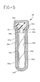
- FIG. 5 shows an additional embodiment of the barrier coating and a tube.
- the alternate embodiment functions in a similar manner to the embodiment illustrated in FIG. 4. Accordingly, similar components performing similar functions will be numbered identically to those components in the embodiment of FIG. 4, except that a suffix " a " will be used to identify those components in FIG. 5.
- Multi-layer barrier coating 45a incorporates both upper portion 50a of stopper 48a , as well as the entire outer surface of tube 42a .
- Multi-layer barrier coating 45a includes serrations 62 at the tube, stopper interface. The serrations are registered so that it can be determined if the sealed container has been tampered with. Such an embodiment may be utilized, for example, for sealing the container with the stopper in place. Once a sample has been placed in the tube, the sample cannot be tampered with by removal of the stopper. Additionally, the serrations may be registered so that it can be determined if the sealed container has been tampered with. Such an arrangement may be appropriate, for example, in drug abuse testing, specimen identification and quality control.
- multi-layer barrier coating 45 is repeatedly or sequentially applied to the inner and/or outer surface of the tube.
- the coating is applied at least twice.
- tubes may contain reagents in the form of additives or coatings on the inner wall of the tube.
- the multi-layer barrier coating forms a substantially clear or translucent barrier. Therefore, the contents of a plastic tube with a multi-layer barrier coating comprising at least two layers of barrier materials are substantially visible to the observer at the same time identifying information may be displayed over the multi-layer barrier coating after it is applied to the plastic tube.
- the first layer of the multi-layer barrier coating may be formed on the tube by dip-coating, roll-coating or spraying acrylate monomer or the blend of monomers, followed by the UV curing process.
- the acrylate polymer material may also be applied to the tube by an evaporation and curing process carried out as described in U.S. Patent No. 5,032,461, the disclosure of which is herein incorporated by reference.
- the acrylate evaporation and curing process involves first atomizing the acrylate monomer into about 50 micron droplets and then flashing them off of a heated surface. This produces an acrylate molecular vapor which has the same chemistry as the starting monomer.
- Acrylates are available with almost any chemistry desired. They usually have either one, two or three acrylate groups per molecule. Various mixtures of mono, di and tri acrylates are useful in the present invention. Most preferable are monoacrylates and diacrylates.
- Acrylates form one of the most reactive classes of chemicals. They cure rapidly when exposed to UV or electron beam radiation to form a cross-linked structure. This imparts high temperature and abrasion resistant properties in the coating.
- the monomer materials utilized are relatively low in molecular weight, between 150 and 1,000 and preferably in the range of 200 to 300 and have vapor pressures between about 1x10 -6 Torr and 1x10 -1 Torr at standard temperature and pressure (i.e., relatively low boiling materials). A vapor pressure of about 1x10 -2 Torr is preferred. Polyfunctional acrylates are especially preferred.
- the monomers employed have at least two double bonds (i.e., a plurality of olefm groups).
- the high-vapor-pressure monomers used in the present invention can be vaporized at low temperatures and thus are not degraded (cracked) by the heating process. The absence of unreactive degradation products means that films formed from these low molecular weight, high-vapor-pressure monomers have reduced volatile levels of components.
- substantially all of the deposited monomer is reactive and will cure to form an integral film when exposed to a source of radiation.
- These properties make it possible to provide substantially continuous coating despite the fact that the film is very thin.
- the cured film exhibits excellent adhesion and is resistant to chemical attack by organic solvents and inorganic salts.
- polyfunctional acrylates are particularly useful monomeric materials.
- the general formula for such polyfunctional acrylates is: wherein:
- Such polyfunctional acrylates may also be used in combination with various monacrylates, such as those having the formula: wherein:
- Curing is accomplished by opening the double bonds of the reactant molecules. This can be accomplished by means of an energy source such as an apparatus which emits infrared, electrons or ultraviolet radiation.
- FIG. 6 illustrates the process for applying an acrylate coating.
- An acrylate monomer 100 is directed through a dielectric evaporator 102 and then through an ultrasonic atomizer 104 and into a vacuum chamber 106 .
- the monomer droplets are atomized ultrasonically and the droplets vaporized where they condense on the rotating tube or film that is loaded on a drum 108.
- the condensed monomer liquid subsequently is radiation cured by means of an electron beam gun 110.
- the second layer of the multi-layer barrier coating may be formed by radio frequency discharge, direct or dual ion beam deposition, sputtering or plasma enhanced chemical vapor deposition, as described in U.S. Patent Nos. 4,698,256, 4,809,876, 4,992,298 and 5,055,318, the disclosures of which are herein incorporated by reference.
- a method of depositing the second layer is provided by establishing a glow discharge plasma in a previously evacuated chamber.
- the plasma is derived from one or more of the gas stream components, and preferably is derived from the gas stream itself.
- the article is positioned in the plasma, preferably adjacent the confined plasma, and the gas stream is controllably flowed into the plasma.
- the thickness of the second layer is about 50A to about 5000 ⁇ and preferably at about 750 ⁇ to about 2000 ⁇ .
- the barrier based film is deposited on the substrate to a desired thickness. A thickness of less than about 5,000 ⁇ may not provide sufficient barrier and a thickness of greater than about 5,000 ⁇ may crack, thus decreasing the effective barrier.
- the thickness of the third oxide coating is about 1,000 ⁇ to about 3,000 ⁇ .
- Another method of depositing a barrier coating is by confining a plasma with magnets.
- the magnetically enhanced method for depositing a silicon oxide based film on a substrate is preferably conducted in a previously evacuated chamber of glow discharge from a gas stream.
- the gas stream preferably comprises at least two components: volatilized organosilicon and organotin components and an oxidizer component such as oxygen, nitrous oxide, carbon dioxide or air and an optionally inert gas component.
- organosilicon and organotin compounds useful for the gas stream in the plasma deposition methods are liquid or gas at about ambient temperature and have a boiling point about 0°C to about 200°C and include tetramethyltin, tetraethyltin, tetraisopropyltin, tetraallyltin, dimethysilane, trimethylsilane, diethylsilane, propylsilane, phenylsilane, hexamethyldisilane, 1,1,2,2-tetramethyldisilane, bis (trimethylsilane)methane, bis (dimethylsilyl) methane, hexamethyldisiloxane, vinyl trimethoxy silane, vinyl triethyoxysilane, ethylmethoxysilane, ethyltrimethoxysilane, divinyltetramethyldisiloxane, hexamethyldsilazane
- organosilicons are 1,1,3,3-tetramethyldisiloxane, trimethylsilane, hexamethyldisiloxane (HMDSO), vinyltrimethylsilane, methyltrimethoxysilane, vinyltrimethoxysilane and hexamethyldisilazane.
- HMDSO hexamethyldisiloxane
- vinyltrimethylsilane methyltrimethoxysilane
- vinyltrimethoxysilane vinyltrimethoxysilane
- hexamethyldisilazane hexamethyldisilazane.
- These preferred organosilicon compounds have boiling points of 71°C, 55.5°C, 102°C, 123°C and 127°C respectively.
- the optional inert gas of the gas stream preferably is helium, argon or nitrogen.
- volatilized organotin and organosilicon components are preferably admixed with the oxygen component and the inert gas component before being flowed into the chamber.
- the quantities of these gases being so admixed are controlled by flow controllers so as to adjustably control the flow rate ratio of the gas stream components.
- Various optical methods known in the art may be used to determine the thickness of the deposited film while in the deposition chamber, or the film thickness can be determined after the article is removed from the deposition chamber.
- the deposition method of the present invention is preferably practiced at relatively high power and quite low pressure.
- a pressure less than about 500 millitorr (mTorr) should be maintained during the deposition, and preferably the chamber is at a pressure between about 43 to about 490 millitorr during the deposition of film.
- Low system pressure results in lower deposition rates whereas higher system pressure provides faster deposition rates.
- a higher system pressure may be used to minimize the amount of heat the substrate is exposed to during deposition because high substrate temperatures are to be avoided for low Tg polymers such as polypropylene and PET (Tg is -10°C and 60°C respectively).
- the substrate is electrically isolated from the deposition system (except for electrical contact with the plasma) and is at a temperature of less than about 80°C during the depositing. That is, the substrate is not deliberately heated.
- the substrate can be any vacuum compatible material, such as plastic.
- One or more gases are supplied to the reaction chamber by a gas supply system 173.
- An electric field is created by a power supply 174.
- the reaction chamber can be of an appropriate type to perform any of the plasma-enhanced chemical vapor deposition (PECVD) or plasma polymerization processes. Furthermore, the reaction chamber may be modified so that one or more articles may be coated with the oxide mixture layer simultaneously within the chamber.
- PECVD plasma-enhanced chemical vapor deposition
- the pressure of the chamber is controlled by a mechanical pump 188 connected to chamber 170 by a valve 190 .
- the tube to be coated is first loaded into chamber 170 in sample holder 172 .
- the pressure of the chamber is reduced to about 5 mTorr by mechanical pump 188.
- the operating pressure of the chamber is about 90 to about 140 mTorr for a PECVD or plasma polymerization process and is achieved by flowing the process gases, oxygen and barrier precursor, into the chamber through monomer inlet 176 .
- the thin film is deposited on the surface of the tube and has a desired uniform thickness or the deposition process may be interrupted periodically to minimize heating of the substrate and/or electrodes and/or physically remove particulate matter from the articles.
- Magnets 196 and 198 are positioned behind electrode 200 to create an appropriate combination of magnetic and electrical fields in the plasma region around the tube.
- the system is suitable for low frequency operation.
- An example frequency is 40kHz.
- an apparatus of the present invention includes a vacuum manifold system 22 .
- the vacuum manifold system includes at least five connections 24, 26, 28, 30 and 32 and a coupling port 34 that is desirably a rubber grommet.
- Valves 42, 44, 46, 48 and 50 lead respectively to a monomer gas source 52 , an oxidizer gas source 54 , a vacuum pump 56 , a vent filter 58 and a diluent gas source 60 respectively.
- the apparatus further includes means for creating energy including an external electrode system 62 and an energy source 64 .
- the energy source preferably includes a tuner 66 , an amplifier 68 and an oscillator 70 .
- the open end of the tube is first connected to the vacuum manifold system at the coupling port and all valves are in a closed position. Then valve 46 is opened and the vacuum pump is initiated to reduce the pressure in the tube to the vacuum region of about 0.001 mTorr to about 100 mTorr.
- Valve 42 is first opened so that the monomer gas component flows into the manifold system at a pressure of about 125 mTorr, a flow rate of about 1.0 sccm, and a room temperature of about 74°F.
- valve 44 is opened so that the oxidizer gas component flows into the manifold system at a pressure of about 175 mTorr, flow rate of about 22 sccm and a temperature of about room temperature or about 74°F.
- the monomer gas component and the oxidizer gas component are preferably admixed with the inert gas component in the manifold system before being flowed into the tube.
- the quantities of these gases being so admixed are controlled by flow controllers so as to adjustably control the flow rate ratio of the reactant gas stream components.
- the mixture of the reactant gas components is achieved inside the tube prior to energizing the electrical system.
- the monomer gas component is preferably HMDSO and the oxidizer gas component is preferably oxygen so as to form and deposit a barrier coating of silicone oxide (SiO x ) on the internal wall surface of a tube.
- the oxidizer gas component is preferably oxygen so as to form and deposit a barrier coating of silicone oxide (SiO x ) on the internal wall surface of a tube.
- the barrier coating is deposited on the internal surface of the tube to a desired thickness.
- the thickness of the coating is about 500 Angstroms ( ⁇ ) to about 5000 ⁇ . Most preferably, the thickness of the oxide coating is about 1000 ⁇ to about 3000 ⁇ .
- a general control system including a computer control portion, is connected to each of the components of the system in a manner to receive status information from and send controlling commands to them.
- Suitable pressure of the reactant gas mixture is between about 70 mTorr and about 2000 mTorr, preferably between about 150 mTorr and 600 mTorr and most preferably about 300 mTorr.
- an organosilicon such as HMDSO and tetramethyltin are used as the monomer gas components at a flow rate of about 0.1 to 50 sccm, at (25°C) and from about 80 mTorr to about 190 mTorr preferably at about 0.5 sccm to about 15 sccm and most preferably at about 1.0 sccm.
- air is used as the oxidizer gas component at a flow rate of about 0.1 to about 50 sccm, (at 25°C) and from about 110 mTorr to about 200 mTorr, preferably at about 15 to about 35 sccm and most preferably at about 22 sccm.
- the barrier film blend thereof used in accordance with this disclosure may contain conventional additives and ingredients which do not adversely affect the properties of articles made therefrom.
- the optional third layer of the multi-layer barrier coating may be formed on the second layer by dip-coating, roll-coating or spraying an aqueous emulsion of the polyvinylidene chloride or homo- or co-polymers, followed by air drying.
- the third layer may preferably be vinylidene chloride-acrylonitrile-methyl methacrylate-methyl acrylate-acrylic acid copolymers, thermosetting epoxy coatings, parylene polymers, or polyesters.
- the third layer is a parylene polymer.
- Parylene is the generic name for members of the polymer series developed by Union Carbide Corporation.
- the base member of the series, called parylene N is poly-p-xylylene, a linear, crystalline material:
- Parylene C a second member of the parylene series is produced from the same monomer as parylene N and modified by the substitution of a chlorine atom for one other aromatic hydrogens:
- Parylene D the third member of the parylene series is produced from the same monomer as parylene N and modified by the substitution of the chlorine atom for two of the aromatic hydrogens:
- the polymer layer is a vinylidene chloride-methyl methacrylate-methacrylate acrylic acid polymer (PVDC).
- PVDC vinylidene chloride-methyl methacrylate-methacrylate acrylic acid polymer
- the third layer of the barrier coating may be a parylene polymer applied to the second layer by a process similar to vacuum metallizing, as described in U.S. Patent Nos. 3,342,754 and 3,300,332, the disclosures of which are herein incorporated by reference.
- the third layer may be vinylidene chloride-acrylonitrile-methyl methacrylate-methyl acrylate-acid acrylic polymer, applied to the second layer by dip-coating, roll-coating or spraying an aqueous emulsion of the polymer, followed by air drying of the coating, as described in U.S. Patent Nos. 5,093,194 and 4,497,859, the disclosure of which are herein incorporated by reference.
- the acrylate coating A and the second mixed layer B may have defects or irregularities C . It is believed that a completely defect-free coverage of the substrate D cannot be achieved with only the acrylate and mixed layer. Therefore, a third coating of PVDC, E is applied over the layer to produce a substantially defect-free barrier coating over the substrate surface.
- substrates can be coated with a barrier coating by the process of the present invention.
- substrates include, but are not limited to packaging, containers, bottles, jars, tubes and medical devices.
- a plastic blood collection tube coated with the multi-layer barrier coating will not interfere with testing and analysis that is typically performed on blood in a tube. Such tests include but are not limited to, routine chemical analysis, biological inertness, hematology, blood chemistry, blood typing, toxicology analysis or therapeutic drug monitoring and other clinical tests involving body fluids. Furthermore, a plastic blood collection tube coated with the barrier coating is capable of being subjected to automated machinery such as centrifuges and may be exposed to certain levels of radiation in the sterilization process with substantially no change in optical or mechanical and functional properties.
- a plastic blood collection tube coated with the multi-layer barrier coating is able to maintain 90% original draw volume over a period of one year.
- Draw volume retention depends on the existence of a particle vacuum, or reduced pressure, inside the tube. The draw volume changes in direct proportion to the change in vacuum (reduced pressure). Therefore, draw volume retention is dependent on good vacuum retention.
- a plastic tube coated with a barrier coating substantially prevents gas permeation through the tube material so as to maintain and enhance the vacuum retention and draw volume retention of the tube.
- Plastic tubes without the multi-layer coating of the present invention may maintain about 90% draw volume for about 3 to 4 months.
- the barrier coating may be hemorepellent and/or have characteristics of a clot activator.
- plastic composite container is evacuated or not evacuated in accordance with this invention.
- the presence of a barrier coating on the outer surface of the container has the effect of maintaining the general integrity of the container holding a sample so that it may be properly disposed of without any contamination to the user. Notable is the clarity of the barrier coating as coated or applied on the container and its abrasion and scratch resistance.
- the barrier coating used in accordance with this disclosure may contain conventional additives and ingredients which do not adversely affect the properties of articles made therefrom.
- a polypropylene (PP) tube was connected to the vacuum manifold system and with external parallel plate electrodes surrounding the outside of the tube.
- a vacuum of about 60 mTorr was first drawn inside the tube.
- air at about 200m Torr was introduced into the tube through the manifold system and the electrodes were energized at 30 watts from a 38MHz oscillator for about 30 seconds to provide a surface activation treatment.
- a monomer gas mixture of tetramethyltin and hexamethyldisilxane vapor (1:20 v/v) was added into the tube through the manifold until the total pressure of the gas mixture was about 250 mTorr.
- the plasma deposition was maintained for about 5 minutes, followed by a 90 second air treatment.
- a PET tube was connected to the vacuum manifold system and to external parallel plate electrodes surrounding the outside of the tube.
- a vacuum of about 60 mTorr was first drawn inside the tube. Then air was introduced into the tube at a pressure of about 150mTorr. Then a mixture of tetramethyltin and hexamethyldisiloxane (1:20 v/v) vapor was introduced into the tube until the total pressure of the gas mixture inside the tube was about 200 Torr.
- the electrodes were energized at 38 MHz and 22 Watts for about 5 minutes so that a plasma was generated inside the tube.
- a Surface Science Model SSx-100 X-ray photoelectron spectromenter was used to determine the atom % of the elements present in the oxide coatings. Film samples were placed inside the spectrometer and the elemental composition was determined of approximately 100 ⁇ into the surface. The surface was then argon ion etched as follows: 5000V and 9-10 mA argon ion beam was directed at the sample surface. After 5 seconds the ESCA spectra was taken and this procedure was repeated for a total of 5 times. The etch time was then increased to 20 seconds followed by ESCA and this process was repeated for a total of ten times.
- ESCA X-ray photoelectron spectromenter
- the etch time was increased to 40 seconds and the ESCA spectra was obtained until the bulk acrylate or the polymer substrate was reached.
- the oxide layer was clearly indicated by the presence of silicon in the ESCA spectra between the etch times of about 0 through about 1.3 minutes. The results are reported in FIG. 10.
- a sample assembly comprising:
- said multi-layer barrier coating includes registered tamper serrations adjacent to said container and said closure interface.
- said second layer is a mixture of SnO x , GeO x or PbO x and aluminum oxide or silicon oxide based composition.
- thermosetting epoxy e.g., parylene polymer, homopolymers, co-polymers, polyesters or vinylidene chloride.
- said first layer comprises polymerized acrylate and said second layer comprises a mixture of tin and silicon oxide and said third layer comprises polyvinylidene chloride.
- the assembly as above further comprising a multi-layer barrier coating over the inner surface of said container, having a first layer including an acrylate primer coating material, a second layer on said first layer of a mixture of metal oxide and an inorganic material.
- a multi-layer barrier coating comprising:
- said second layer is a mixture of SnO x , GeO x or PbO x and aluminum oxide or silicon oxide.
- a method of depositing a multilayer barrier coating on a plastic substrate in a previously evacuated chamber comprising:
- a method of depositing a barrier coating on a plastic substrate in a previously evacuated chamber comprising:
- a method for applying a barrier film coating to the interior wall surface of a plastic substrate comprising:
- a method for applying a barrier film coating to the interior wall surface of a plastic substrate comprising:
- step (d) further includes a diluent gas.
- a method for applying a barrier film coating to the interior wall surface of a plastic substrate comprising:
- step (d) further includes a diluent gas.
- a method for applying a barrier film coating to the interior wall surface of a plastic substrate comprising:
Landscapes
- Chemical & Material Sciences (AREA)
- Chemical Kinetics & Catalysis (AREA)
- Health & Medical Sciences (AREA)
- Organic Chemistry (AREA)
- Engineering & Computer Science (AREA)
- Medicinal Chemistry (AREA)
- Polymers & Plastics (AREA)
- General Chemical & Material Sciences (AREA)
- Mechanical Engineering (AREA)
- Metallurgy (AREA)
- Materials Engineering (AREA)
- Inorganic Chemistry (AREA)
- General Health & Medical Sciences (AREA)
- Hematology (AREA)
- Analytical Chemistry (AREA)
- Clinical Laboratory Science (AREA)
- Life Sciences & Earth Sciences (AREA)
- Physics & Mathematics (AREA)
- Plasma & Fusion (AREA)
- Wood Science & Technology (AREA)
- Animal Behavior & Ethology (AREA)
- Pharmacology & Pharmacy (AREA)
- Public Health (AREA)
- Veterinary Medicine (AREA)
- Laminated Bodies (AREA)
- Measurement Of The Respiration, Hearing Ability, Form, And Blood Characteristics Of Living Organisms (AREA)
- Medical Preparation Storing Or Oral Administration Devices (AREA)
- Application Of Or Painting With Fluid Materials (AREA)
Applications Claiming Priority (3)
| Application Number | Priority Date | Filing Date | Title |
|---|---|---|---|
| US594078 | 1996-01-30 | ||
| US08/594,078 US5738920A (en) | 1996-01-30 | 1996-01-30 | Blood collection tube assembly |
| EP97101063A EP0787823B1 (de) | 1996-01-30 | 1997-01-24 | Verfahren zum Auftragen einer Sperrschicht auf einem Kunststoffsubstrat |
Related Parent Applications (1)
| Application Number | Title | Priority Date | Filing Date |
|---|---|---|---|
| EP97101063A Division EP0787823B1 (de) | 1996-01-30 | 1997-01-24 | Verfahren zum Auftragen einer Sperrschicht auf einem Kunststoffsubstrat |
Publications (3)
| Publication Number | Publication Date |
|---|---|
| EP1486584A2 true EP1486584A2 (de) | 2004-12-15 |
| EP1486584A3 EP1486584A3 (de) | 2005-06-22 |
| EP1486584B1 EP1486584B1 (de) | 2007-06-20 |
Family
ID=24377437
Family Applications (2)
| Application Number | Title | Priority Date | Filing Date |
|---|---|---|---|
| EP04021084A Expired - Lifetime EP1486584B1 (de) | 1996-01-30 | 1997-01-24 | Verfahren zum Auftragen einer Sperrbeschichtung auf ein Kunststoffsubstrat |
| EP97101063A Expired - Lifetime EP0787823B1 (de) | 1996-01-30 | 1997-01-24 | Verfahren zum Auftragen einer Sperrschicht auf einem Kunststoffsubstrat |
Family Applications After (1)
| Application Number | Title | Priority Date | Filing Date |
|---|---|---|---|
| EP97101063A Expired - Lifetime EP0787823B1 (de) | 1996-01-30 | 1997-01-24 | Verfahren zum Auftragen einer Sperrschicht auf einem Kunststoffsubstrat |
Country Status (11)
| Country | Link |
|---|---|
| US (2) | US5738920A (de) |
| EP (2) | EP1486584B1 (de) |
| JP (1) | JP3224349B2 (de) |
| KR (1) | KR100188291B1 (de) |
| AU (1) | AU1231997A (de) |
| BR (1) | BR9700733A (de) |
| CA (1) | CA2195049C (de) |
| DE (2) | DE69735734T2 (de) |
| ES (1) | ES2258783T3 (de) |
| SG (1) | SG66348A1 (de) |
| TW (1) | TW362018B (de) |
Cited By (1)
| Publication number | Priority date | Publication date | Assignee | Title |
|---|---|---|---|---|
| WO2011035449A2 (de) | 2009-09-22 | 2011-03-31 | Medmix System Ag | Versiegelter behälter mit verschiebbarem kolben |
Families Citing this family (67)
| Publication number | Priority date | Publication date | Assignee | Title |
|---|---|---|---|---|
| TW434301B (en) * | 1996-01-30 | 2001-05-16 | Becton Dickinson Co | Non-ideal barrier coating composition comprising organic and inorganic materials |
| US5955161A (en) * | 1996-01-30 | 1999-09-21 | Becton Dickinson And Company | Blood collection tube assembly |
| US6049736A (en) * | 1997-09-03 | 2000-04-11 | Medtronic, Inc. | Implantable medical device with electrode lead having improved surface characteristics |
| US6224948B1 (en) | 1997-09-29 | 2001-05-01 | Battelle Memorial Institute | Plasma enhanced chemical deposition with low vapor pressure compounds |
| DE19801320B4 (de) * | 1998-01-16 | 2004-08-26 | Schott Glas | Befüllter und verschlossener Kunststoffbehälter und Verfahren zu seiner Herstellung |
| US6428527B1 (en) * | 1998-11-10 | 2002-08-06 | Becton, Dickinson And Company | Method for coating a blood collection device |
| US6207239B1 (en) | 1998-12-16 | 2001-03-27 | Battelle Memorial Institute | Plasma enhanced chemical deposition of conjugated polymer |
| US6228434B1 (en) * | 1998-12-16 | 2001-05-08 | Battelle Memorial Institute | Method of making a conformal coating of a microtextured surface |
| US6274204B1 (en) | 1998-12-16 | 2001-08-14 | Battelle Memorial Institute | Method of making non-linear optical polymer |
| US6207238B1 (en) * | 1998-12-16 | 2001-03-27 | Battelle Memorial Institute | Plasma enhanced chemical deposition for high and/or low index of refraction polymers |
| US6228436B1 (en) * | 1998-12-16 | 2001-05-08 | Battelle Memorial Institute | Method of making light emitting polymer composite material |
| US6054188A (en) * | 1999-08-02 | 2000-04-25 | Becton Dickinson And Company | Non-ideal barrier coating architecture and process for applying the same to plastic substrates |
| US20100330748A1 (en) | 1999-10-25 | 2010-12-30 | Xi Chu | Method of encapsulating an environmentally sensitive device |
| US6413645B1 (en) | 2000-04-20 | 2002-07-02 | Battelle Memorial Institute | Ultrabarrier substrates |
| US20070196682A1 (en) * | 1999-10-25 | 2007-08-23 | Visser Robert J | Three dimensional multilayer barrier and method of making |
| US6623861B2 (en) * | 2001-04-16 | 2003-09-23 | Battelle Memorial Institute | Multilayer plastic substrates |
| US6866901B2 (en) | 1999-10-25 | 2005-03-15 | Vitex Systems, Inc. | Method for edge sealing barrier films |
| US20090191342A1 (en) * | 1999-10-25 | 2009-07-30 | Vitex Systems, Inc. | Method for edge sealing barrier films |
| EP1990092B1 (de) | 2001-03-09 | 2010-02-10 | Gen-Probe Incorporated | Durchlässige Haube |
| US7288293B2 (en) * | 2001-03-27 | 2007-10-30 | Apit Corp. S.A. | Process for plasma surface treatment and device for realizing the process |
| US20090208754A1 (en) * | 2001-09-28 | 2009-08-20 | Vitex Systems, Inc. | Method for edge sealing barrier films |
| GB0208261D0 (en) * | 2002-04-10 | 2002-05-22 | Dow Corning | An atmospheric pressure plasma assembly |
| US8900366B2 (en) * | 2002-04-15 | 2014-12-02 | Samsung Display Co., Ltd. | Apparatus for depositing a multilayer coating on discrete sheets |
| US8808457B2 (en) | 2002-04-15 | 2014-08-19 | Samsung Display Co., Ltd. | Apparatus for depositing a multilayer coating on discrete sheets |
| US20030200727A1 (en) * | 2002-04-26 | 2003-10-30 | Becton, Dickinson And Company | Collection assembly |
| KR20040001229A (ko) * | 2002-06-27 | 2004-01-07 | 주식회사 메디진 | 샘플 튜브용 밀폐뚜껑 |
| US20050008763A1 (en) * | 2002-09-24 | 2005-01-13 | Schachter Steven C. | Antimicrobial coatings for medical applications |
| US7510913B2 (en) * | 2003-04-11 | 2009-03-31 | Vitex Systems, Inc. | Method of making an encapsulated plasma sensitive device |
| US7648925B2 (en) * | 2003-04-11 | 2010-01-19 | Vitex Systems, Inc. | Multilayer barrier stacks and methods of making multilayer barrier stacks |
| US20050238816A1 (en) * | 2004-04-23 | 2005-10-27 | Li Hou | Method and apparatus of depositing low temperature inorganic films on plastic substrates |
| DE202004007921U1 (de) * | 2004-05-17 | 2005-09-22 | Amoena Medizin-Orthopädie-Technik GmbH | Brustprothese |
| US7767498B2 (en) * | 2005-08-25 | 2010-08-03 | Vitex Systems, Inc. | Encapsulated devices and method of making |
| WO2007112312A2 (en) * | 2006-03-24 | 2007-10-04 | 3M Innovative Properties Company | Medicinal formulation container with a treated metal surface |
| US8387810B2 (en) * | 2007-04-16 | 2013-03-05 | Becton, Dickinson And Company | Pierceable cap having piercing extensions for a sample container |
| US8387811B2 (en) * | 2007-04-16 | 2013-03-05 | Bd Diagnostics | Pierceable cap having piercing extensions |
| GB0715170D0 (en) * | 2007-08-03 | 2007-09-12 | Enigma Diagnostics Ltd | Reaction vessel |
| FR2929295A1 (fr) * | 2008-03-25 | 2009-10-02 | Becton Dickinson France Soc Pa | Appareil pour le traitement par plasma de corps creux |
| FR2929294A1 (fr) * | 2008-03-25 | 2009-10-02 | Becton Dickinson France Soc Pa | Appareil pour le traitement par plasma de corps creux |
| US9184410B2 (en) | 2008-12-22 | 2015-11-10 | Samsung Display Co., Ltd. | Encapsulated white OLEDs having enhanced optical output |
| US9337446B2 (en) * | 2008-12-22 | 2016-05-10 | Samsung Display Co., Ltd. | Encapsulated RGB OLEDs having enhanced optical output |
| US20100167002A1 (en) * | 2008-12-30 | 2010-07-01 | Vitex Systems, Inc. | Method for encapsulating environmentally sensitive devices |
| EP2251453B1 (de) | 2009-05-13 | 2013-12-11 | SiO2 Medical Products, Inc. | Behälterhalterung |
| US7985188B2 (en) | 2009-05-13 | 2011-07-26 | Cv Holdings Llc | Vessel, coating, inspection and processing apparatus |
| WO2013170052A1 (en) | 2012-05-09 | 2013-11-14 | Sio2 Medical Products, Inc. | Saccharide protective coating for pharmaceutical package |
| US9458536B2 (en) | 2009-07-02 | 2016-10-04 | Sio2 Medical Products, Inc. | PECVD coating methods for capped syringes, cartridges and other articles |
| US8590338B2 (en) * | 2009-12-31 | 2013-11-26 | Samsung Mobile Display Co., Ltd. | Evaporator with internal restriction |
| US11624115B2 (en) | 2010-05-12 | 2023-04-11 | Sio2 Medical Products, Inc. | Syringe with PECVD lubrication |
| US8802603B2 (en) | 2010-06-17 | 2014-08-12 | Becton, Dickinson And Company | Medical components having coated surfaces exhibiting low friction and low reactivity |
| US9878101B2 (en) | 2010-11-12 | 2018-01-30 | Sio2 Medical Products, Inc. | Cyclic olefin polymer vessels and vessel coating methods |
| US9272095B2 (en) | 2011-04-01 | 2016-03-01 | Sio2 Medical Products, Inc. | Vessels, contact surfaces, and coating and inspection apparatus and methods |
| US11116695B2 (en) | 2011-11-11 | 2021-09-14 | Sio2 Medical Products, Inc. | Blood sample collection tube |
| WO2013071138A1 (en) | 2011-11-11 | 2013-05-16 | Sio2 Medical Products, Inc. | PASSIVATION, pH PROTECTIVE OR LUBRICITY COATING FOR PHARMACEUTICAL PACKAGE, COATING PROCESS AND APPARATUS |
| US20150297800A1 (en) | 2012-07-03 | 2015-10-22 | Sio2 Medical Products, Inc. | SiOx BARRIER FOR PHARMACEUTICAL PACKAGE AND COATING PROCESS |
| DE102012110131A1 (de) | 2012-10-24 | 2014-04-24 | Schott Ag | Verbundmaterial für ein pharmazeutisches Packmittel, Verfahren zu dessen Herstellung und Verwendung des Verbundmaterials |
| JP6509734B2 (ja) | 2012-11-01 | 2019-05-08 | エスアイオーツー・メディカル・プロダクツ・インコーポレイテッド | 皮膜検査方法 |
| EP2920567B1 (de) | 2012-11-16 | 2020-08-19 | SiO2 Medical Products, Inc. | Verfahren und vorrichtung zur erkennung von schnellen sperrbeschichtungsintegritätseigenschaften |
| US9764093B2 (en) | 2012-11-30 | 2017-09-19 | Sio2 Medical Products, Inc. | Controlling the uniformity of PECVD deposition |
| WO2014085348A2 (en) | 2012-11-30 | 2014-06-05 | Sio2 Medical Products, Inc. | Controlling the uniformity of pecvd deposition on medical syringes, cartridges, and the like |
| GB201222841D0 (en) * | 2012-12-18 | 2013-01-30 | P2I Ltd | Deposition of electrically conductive polymers |
| US9662450B2 (en) | 2013-03-01 | 2017-05-30 | Sio2 Medical Products, Inc. | Plasma or CVD pre-treatment for lubricated pharmaceutical package, coating process and apparatus |
| US9937099B2 (en) | 2013-03-11 | 2018-04-10 | Sio2 Medical Products, Inc. | Trilayer coated pharmaceutical packaging with low oxygen transmission rate |
| KR102167557B1 (ko) | 2013-03-11 | 2020-10-20 | 에스아이오2 메디컬 프로덕츠, 인크. | 코팅된 패키징 |
| US20160017490A1 (en) | 2013-03-15 | 2016-01-21 | Sio2 Medical Products, Inc. | Coating method |
| EP3122917B1 (de) | 2014-03-28 | 2020-05-06 | SiO2 Medical Products, Inc. | Antistatische beschichtungen für kunststoffbehälter |
| BR112018003051B1 (pt) | 2015-08-18 | 2022-12-06 | Sio2 Medical Products, Inc | Tubo de coleta de sangue submetido a vácuo |
| WO2017177120A1 (en) * | 2016-04-08 | 2017-10-12 | Sio2 Medical Products, Inc. | Method for applying a pecvd lubricity layer with a moving gas inlet |
| EP4544094A1 (de) * | 2022-06-21 | 2025-04-30 | SiO2 Medical Products, LLC | Verfahren und systeme zur beschichtung, reinigung und inspektion pharmazeutischer behälter auf partikel und defekte |
Family Cites Families (31)
| Publication number | Priority date | Publication date | Assignee | Title |
|---|---|---|---|---|
| US4096315A (en) * | 1976-12-15 | 1978-06-20 | The United States Of America As Represented By The Administrator Of The National Aeronautics And Space Administration | Process for producing a well-adhered durable optical coating on an optical plastic substrate |
| US4140814A (en) * | 1977-12-01 | 1979-02-20 | Texas Instruments Incorporated | Plasma deposition of transparent conductive layers |
| DE3107421C2 (de) * | 1981-02-27 | 1985-02-14 | Heraeus Quarzschmelze Gmbh, 6450 Hanau | Glocke aus Quarzgut für die Abscheidung von Poly-Silizium |
| EP0110022B1 (de) | 1982-11-26 | 1987-07-15 | Lonza Ag | Isoliereinsatz für Lager- und Transportbehälter |
| GB2139647B (en) * | 1983-02-24 | 1986-11-19 | Boc Group Plc | Bottle coated ion-plating or magnetron sputtering |
| US4478874A (en) * | 1983-12-09 | 1984-10-23 | Cosden Technology, Inc. | Methods for improving the gas barrier properties of polymeric containers |
| US5032461A (en) | 1983-12-19 | 1991-07-16 | Spectrum Control, Inc. | Method of making a multi-layered article |
| US4842893A (en) | 1983-12-19 | 1989-06-27 | Spectrum Control, Inc. | High speed process for coating substrates |
| US4490774A (en) | 1983-12-19 | 1984-12-25 | General Electric Company | Capacitors containing polyfunctional acrylate polymers as dielectrics |
| US4698256A (en) | 1984-04-02 | 1987-10-06 | American Cyanamid Company | Articles coated with adherent diamondlike carbon films |
| US4647818A (en) | 1984-04-16 | 1987-03-03 | Sfe Technologies | Nonthermionic hollow anode gas discharge electron beam source |
| EP0242460A1 (de) | 1985-01-18 | 1987-10-28 | SPECTRUM CONTROL, INC. (a Pennsylvania corporation) | Zerstäuber zum Verdampfen eines Monomers |
| US4954371A (en) | 1986-06-23 | 1990-09-04 | Spectrum Control, Inc. | Flash evaporation of monomer fluids |
| US5019243A (en) * | 1987-04-03 | 1991-05-28 | Mcewen James A | Apparatus for collecting blood |
| US4809876A (en) | 1987-08-27 | 1989-03-07 | Aluminum Company Of America | Container body having improved gas barrier properties |
| US4846101A (en) * | 1988-07-01 | 1989-07-11 | Becton, Dickinson And Company | Apparatus for plasma treatment of small diameter tubes |
| US4992298A (en) | 1988-10-11 | 1991-02-12 | Beamalloy Corporation | Dual ion beam ballistic alloying process |
| US5110633A (en) * | 1989-09-01 | 1992-05-05 | Ciba-Geigy Corporation | Process for coating plastics articles |
| US5093194A (en) | 1989-11-01 | 1992-03-03 | Mobil Oil Corporation | Oriented multilayer heat sealable packaging film |
| CA2040638A1 (en) * | 1990-04-20 | 1991-10-21 | Gedeon I. Deak | Barrier materials useful for packaging |
| US5158750A (en) * | 1990-06-06 | 1992-10-27 | Praxair S.T. Technology, Inc. | Boron nitride crucible |
| EP0470777A3 (en) * | 1990-08-07 | 1993-06-02 | The Boc Group, Inc. | Thin gas barrier films and rapid deposition method therefor |
| US5238746A (en) * | 1990-11-06 | 1993-08-24 | Matsushita Electric Industrial Co., Ltd. | Fluorocarbon-based polymer lamination coating film and method of manufacturing the same |
| JP2637869B2 (ja) * | 1990-12-10 | 1997-08-06 | 松下電器産業株式会社 | 吸着単分子膜及びその製造方法 |
| US5496295A (en) * | 1991-12-18 | 1996-03-05 | Minnesota Mining And Manufacturing Company | Multilayered barrier structures |
| AU669754B2 (en) * | 1992-12-18 | 1996-06-20 | Becton Dickinson & Company | Barrier coating |
| US5356718A (en) * | 1993-02-16 | 1994-10-18 | Ppg Industries, Inc. | Coating apparatus, method of coating glass, compounds and compositions for coating glasss and coated glass substrates |
| FI961478A7 (fi) * | 1993-10-04 | 1996-04-02 | 3M Innovative Properties Company | Sillastettu akrylaattipäällyste kondensaattorin eristeiden ja happisulkujen muodostamiseen |
| US5440446A (en) * | 1993-10-04 | 1995-08-08 | Catalina Coatings, Inc. | Acrylate coating material |
| PE47195A1 (es) * | 1994-02-16 | 1996-02-07 | Coca Cola Co | Recipientes huecos con superficie interna inerte o impermeable obtenida mediante reaccion de la superficie facilitada por plasma o polimerizacion sobre la superficie |
| US5545375A (en) * | 1994-10-03 | 1996-08-13 | Becton, Dickinson And Company | Blood collection tube assembly |
-
1996
- 1996-01-30 US US08/594,078 patent/US5738920A/en not_active Expired - Lifetime
- 1996-12-17 TW TW085115580A patent/TW362018B/zh active
-
1997
- 1997-01-14 CA CA002195049A patent/CA2195049C/en not_active Expired - Lifetime
- 1997-01-21 BR BR9700733A patent/BR9700733A/pt not_active IP Right Cessation
- 1997-01-24 EP EP04021084A patent/EP1486584B1/de not_active Expired - Lifetime
- 1997-01-24 KR KR1019970001985A patent/KR100188291B1/ko not_active Expired - Lifetime
- 1997-01-24 JP JP01136597A patent/JP3224349B2/ja not_active Expired - Lifetime
- 1997-01-24 ES ES97101063T patent/ES2258783T3/es not_active Expired - Lifetime
- 1997-01-24 AU AU12319/97A patent/AU1231997A/en not_active Abandoned
- 1997-01-24 DE DE69735734T patent/DE69735734T2/de not_active Expired - Lifetime
- 1997-01-24 EP EP97101063A patent/EP0787823B1/de not_active Expired - Lifetime
- 1997-01-24 DE DE69737837T patent/DE69737837T2/de not_active Expired - Lifetime
- 1997-01-30 SG SG1997000204A patent/SG66348A1/en unknown
- 1997-03-25 US US08/824,218 patent/US6013337A/en not_active Expired - Lifetime
Cited By (1)
| Publication number | Priority date | Publication date | Assignee | Title |
|---|---|---|---|---|
| WO2011035449A2 (de) | 2009-09-22 | 2011-03-31 | Medmix System Ag | Versiegelter behälter mit verschiebbarem kolben |
Also Published As
| Publication number | Publication date |
|---|---|
| EP0787823A2 (de) | 1997-08-06 |
| KR970058684A (ko) | 1997-08-12 |
| CA2195049C (en) | 2000-08-29 |
| EP1486584A3 (de) | 2005-06-22 |
| TW362018B (en) | 1999-06-21 |
| EP1486584B1 (de) | 2007-06-20 |
| US5738920A (en) | 1998-04-14 |
| DE69737837D1 (de) | 2007-08-02 |
| JP3224349B2 (ja) | 2001-10-29 |
| DE69737837T2 (de) | 2008-02-21 |
| BR9700733A (pt) | 1998-10-06 |
| SG66348A1 (en) | 1999-07-20 |
| AU1231997A (en) | 1997-08-07 |
| EP0787823B1 (de) | 2006-04-26 |
| EP0787823A3 (de) | 2001-08-01 |
| CA2195049A1 (en) | 1997-07-31 |
| US6013337A (en) | 2000-01-11 |
| ES2258783T3 (es) | 2006-09-01 |
| MX9700684A (es) | 1997-07-31 |
| DE69735734D1 (de) | 2006-06-01 |
| DE69735734T2 (de) | 2007-04-12 |
| KR100188291B1 (ko) | 1999-06-01 |
| JPH09253078A (ja) | 1997-09-30 |
Similar Documents
| Publication | Publication Date | Title |
|---|---|---|
| EP1486584B1 (de) | Verfahren zum Auftragen einer Sperrbeschichtung auf ein Kunststoffsubstrat | |
| US5763033A (en) | Blood collection tube assembly | |
| US5683771A (en) | Blood collection tube assembly | |
| US5545375A (en) | Blood collection tube assembly | |
| US5955161A (en) | Blood collection tube assembly | |
| EP0787824B1 (de) | Behälter mit einer Sperrbeschichtung einer nicht idealer Schichtzusammensetzung | |
| CA2195048C (en) | Blood collection tube assembly | |
| EP0789092B1 (de) | Blutentnahmeröhrchen | |
| CA2277679C (en) | Blood collection tube assembly | |
| AU709857B2 (en) | Blood collection tube assembly | |
| MXPA97000684A (en) | Pipe assembly for san collection | |
| CA2170809A1 (en) | Blood collection tube assembly | |
| MXPA97000636A (en) | Pipe assembly for san collection | |
| MXPA97000640A (en) | Pipe assembly for san collection | |
| MXPA97000639A (en) | Pipe assembly for san collection | |
| CA2271504A1 (en) | Blood collection tube assembly |
Legal Events
| Date | Code | Title | Description |
|---|---|---|---|
| PUAI | Public reference made under article 153(3) epc to a published international application that has entered the european phase |
Free format text: ORIGINAL CODE: 0009012 |
|
| 17P | Request for examination filed |
Effective date: 20040904 |
|
| AC | Divisional application: reference to earlier application |
Ref document number: 0787823 Country of ref document: EP Kind code of ref document: P |
|
| AK | Designated contracting states |
Kind code of ref document: A2 Designated state(s): DE ES FR GB IT |
|
| PUAL | Search report despatched |
Free format text: ORIGINAL CODE: 0009013 |
|
| AK | Designated contracting states |
Kind code of ref document: A3 Designated state(s): DE ES FR GB IT |
|
| AKX | Designation fees paid |
Designated state(s): DE ES FR GB IT |
|
| GRAP | Despatch of communication of intention to grant a patent |
Free format text: ORIGINAL CODE: EPIDOSNIGR1 |
|
| GRAS | Grant fee paid |
Free format text: ORIGINAL CODE: EPIDOSNIGR3 |
|
| GRAA | (expected) grant |
Free format text: ORIGINAL CODE: 0009210 |
|
| AC | Divisional application: reference to earlier application |
Ref document number: 0787823 Country of ref document: EP Kind code of ref document: P |
|
| AK | Designated contracting states |
Kind code of ref document: B1 Designated state(s): DE ES FR GB IT |
|
| REG | Reference to a national code |
Ref country code: GB Ref legal event code: FG4D |
|
| REF | Corresponds to: |
Ref document number: 69737837 Country of ref document: DE Date of ref document: 20070802 Kind code of ref document: P |
|
| ET | Fr: translation filed | ||
| PG25 | Lapsed in a contracting state [announced via postgrant information from national office to epo] |
Ref country code: ES Free format text: LAPSE BECAUSE OF FAILURE TO SUBMIT A TRANSLATION OF THE DESCRIPTION OR TO PAY THE FEE WITHIN THE PRESCRIBED TIME-LIMIT Effective date: 20071001 |
|
| PLBE | No opposition filed within time limit |
Free format text: ORIGINAL CODE: 0009261 |
|
| STAA | Information on the status of an ep patent application or granted ep patent |
Free format text: STATUS: NO OPPOSITION FILED WITHIN TIME LIMIT |
|
| PG25 | Lapsed in a contracting state [announced via postgrant information from national office to epo] |
Ref country code: IT Free format text: LAPSE BECAUSE OF FAILURE TO SUBMIT A TRANSLATION OF THE DESCRIPTION OR TO PAY THE FEE WITHIN THE PRESCRIBED TIME-LIMIT Effective date: 20070620 |
|
| 26N | No opposition filed |
Effective date: 20080325 |
|
| REG | Reference to a national code |
Ref country code: FR Ref legal event code: PLFP Year of fee payment: 20 |
|
| PGFP | Annual fee paid to national office [announced via postgrant information from national office to epo] |
Ref country code: GB Payment date: 20151224 Year of fee payment: 20 |
|
| PGFP | Annual fee paid to national office [announced via postgrant information from national office to epo] |
Ref country code: FR Payment date: 20151222 Year of fee payment: 20 |
|
| PGFP | Annual fee paid to national office [announced via postgrant information from national office to epo] |
Ref country code: DE Payment date: 20151217 Year of fee payment: 20 |
|
| REG | Reference to a national code |
Ref country code: DE Ref legal event code: R071 Ref document number: 69737837 Country of ref document: DE |
|
| REG | Reference to a national code |
Ref country code: GB Ref legal event code: PE20 Expiry date: 20170123 |
|
| PG25 | Lapsed in a contracting state [announced via postgrant information from national office to epo] |
Ref country code: GB Free format text: LAPSE BECAUSE OF EXPIRATION OF PROTECTION Effective date: 20170123 |