EP1486401B1 - Frame - Google Patents
Frame Download PDFInfo
- Publication number
- EP1486401B1 EP1486401B1 EP04102521A EP04102521A EP1486401B1 EP 1486401 B1 EP1486401 B1 EP 1486401B1 EP 04102521 A EP04102521 A EP 04102521A EP 04102521 A EP04102521 A EP 04102521A EP 1486401 B1 EP1486401 B1 EP 1486401B1
- Authority
- EP
- European Patent Office
- Prior art keywords
- frame according
- main
- main carriers
- openings
- carriers
- Prior art date
- Legal status (The legal status is an assumption and is not a legal conclusion. Google has not performed a legal analysis and makes no representation as to the accuracy of the status listed.)
- Not-in-force
Links
Images
Classifications
-
- B—PERFORMING OPERATIONS; TRANSPORTING
- B60—VEHICLES IN GENERAL
- B60P—VEHICLES ADAPTED FOR LOAD TRANSPORTATION OR TO TRANSPORT, TO CARRY, OR TO COMPRISE SPECIAL LOADS OR OBJECTS
- B60P3/00—Vehicles adapted to transport, to carry or to comprise special loads or objects
- B60P3/22—Tank vehicles
- B60P3/224—Tank vehicles comprising auxiliary devices, e.g. for unloading or level indicating
- B60P3/225—Adaptations for pumps or valves
-
- A—HUMAN NECESSITIES
- A01—AGRICULTURE; FORESTRY; ANIMAL HUSBANDRY; HUNTING; TRAPPING; FISHING
- A01M—CATCHING, TRAPPING OR SCARING OF ANIMALS; APPARATUS FOR THE DESTRUCTION OF NOXIOUS ANIMALS OR NOXIOUS PLANTS
- A01M7/00—Special adaptations or arrangements of liquid-spraying apparatus for purposes covered by this subclass
- A01M7/0082—Undercarriages, frames, mountings, couplings, tanks
-
- B—PERFORMING OPERATIONS; TRANSPORTING
- B62—LAND VEHICLES FOR TRAVELLING OTHERWISE THAN ON RAILS
- B62D—MOTOR VEHICLES; TRAILERS
- B62D21/00—Understructures, i.e. chassis frame on which a vehicle body may be mounted
- B62D21/18—Understructures, i.e. chassis frame on which a vehicle body may be mounted characterised by the vehicle type and not provided for in groups B62D21/02 - B62D21/17
- B62D21/186—Understructures, i.e. chassis frame on which a vehicle body may be mounted characterised by the vehicle type and not provided for in groups B62D21/02 - B62D21/17 for building site vehicles or multi-purpose tractors
Definitions
- the invention relates to a frame for an agricultural implement having first and second longitudinally extending main beams, the main beams being spaced transversely from one another and at least one main beam having an apertured portion with a container supported on the main beams between the main carriers positioned outlet channel and a piping arrangement which extends substantially horizontally and is guided from the outlet channel through the opening of the at least one main carrier and leads to a location outside the frame.
- Agricultural machines such.
- the main frame typically includes larger longitudinally extending main frame rails or rails supporting the machine cab, driveline, various liquid containers, including larger chemical solution tanks, and pipelines. Cables for the containers and other pipelines, which are arranged between the main frame members, are often difficult to access. Therefore, piping must be routed either above or below the main frame members to locations outside the main frame members to be easily accessible to an operator.
- Such pipe installations require pipe bends and additional pipe extensions, resulting in an unsightly and over-crowded appearance of the machine. The piping is harder to clean due to the increased length and non-linear installation.
- Containers must be mounted raised from the main frame to allow the required routing of lines around the main frame members. This leads to higher transport heights and a higher center of gravity of the machine.
- US 5,593,070 which forms the preamble of claim 1, discloses a tanker vehicle comprising a tank mounted on a frame structure with a piping system, wherein the piping system between tank and frame construction is led to the outside.
- the vehicle disclosed here essentially has the above-mentioned disadvantages.
- US 5,135,258 describes a trailer for motorcycles, which has an integrated tank apparatus comprising fuel-fillable and mounted below a frame construction of the trailer tank, wherein a tank line for discharging the tanks is guided through the frame.
- a tank line for discharging the tanks is guided through the frame.
- the object underlying the invention is seen to provide a framework of the type mentioned, by which the aforementioned problems are overcome.
- a frame of the aforementioned type has an opening which is provided with at least one reinforcing element in order to stabilize the at least one main carrier in the region of the opening.
- An inventive frame for an agricultural device for example for a self-propelled sprayer, has tubular main carrier on which a container and a piping arrangement are mounted. Between the main carriers, an outlet channel is arranged. Furthermore, a substantial portion of the tubing arrangement is interposed between the main beams and between upper and lower levels of the main beams to protect the piping arrangement and to achieve a better appearance.
- the vertically oriented walls of the main beams have round openings reinforced by round tubes.
- the pipes are firmly connected to the walls to seal the area around the openings and to prevent the ingress of contaminants into the main beams.
- the round tubes have one Separation gap on to provide a torsional flexibility of the main frame, while high voltages are avoided in the joints between the round tubes and the walls.
- the round tubes provide a horizontally oriented passageway for a fluid line extending between the outlet channel and a location external to the main frame to reduce pipe length, eliminate pipe bends, improve appearance, improve cleaning functions for the pipes and to allow a deep attachment of the container on the main frame.
- reinforced openings which pass through the end portions of the main carrier, hydraulic lines and cylinders are accommodated, are provided by the various functions for the axle assemblies. Lines and cylinders are protected by the main beams, as a substantial part of which is located between the planes defined by the top and bottom of the main beams.
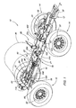
- FIG 1 is a part of an agricultural device, such.
- the main frame 12 is supported for movement across a field in a forward direction (F) of front axle controllable assemblies 14 and rear axle assemblies 16.
- the main frame 12 includes first and second longitudinally extending tubular main beams or rails 21, 22 which are connected to a front axle support frame 24 for the front axle assemblies 14 and to a rear axle support frame 26 for the rear axle assemblies 16.
- a motor-supporting frame 30 projects from the Vorderachsstützstrahlen 24 in the forward direction (F).
- the engine operates hydraulic drive means 32, which are arranged on the axle assemblies 14, 16 and drive the self-propelled sprayer 10.
- Various containers 36 are carried by container supports 38, including a larger container 36 for liquid.
- the container 36 has a lower outlet channel 40 which is arranged between the main supports 21, 22 and between the support frames 24, 26.
- a tubing assembly 50 is connected to the outlet channel 40 between the main supports 21, 22, wherein a liquid-transmitting connection to the container 36 is made.
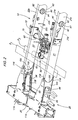
- the main beams 21, 22 have upper walls 21a, 22a and lower walls 21b, 22b joined together by opposite side walls 21c, 22c, thereby forming a substantially rectangular beam cross-section.
- the upper and lower walls 21a, 22a, 21b, 22b define parallel, horizontally oriented upper and lower planes (P1, P2) that lie in the region of the tubing assembly 50.
- the outlet channel 40 and the piping arrangement 50 lie substantially between the main beams 21, 22 between the planes P1, P2.
- the central portions of the main beams 21, 22 have openings 61, 62 for facilitating routing of ducts from an area between the inner side walls 22c to an area outside the main frame 12, while a wiring laid substantially between the levels P1, P2 is maintained to protect the lines, as well as a better appearance and a more straight course with minimal vertical changes in profile can be achieved.
- a supply line 70 extends through one of the openings 62 and constitutes a liquid line arranged horizontally between the outlet channel 40 and one outside the main carrier 21, 22.
- Operation control valve 72 is arranged.
- the outlet channel 40, the pipe assembly 50, including existing actuators, valves 72 and supply lines 70, as well as the hydraulically operated axle components 28 are located substantially between the planes P1, P2.
- Different types of control lines 76 including electrical and hydraulic lines, can be used between areas inside and outside the main carrier 21, 22 through the openings 61, 62 are laid, instead of above or below the main beams 21, 22nd
- the openings 61, 62 have tubular members or open cylindrical profiles 80 which are welded to the opposite side walls 21c and 22c of each main carrier 21 and 22, respectively.
- the profiles 80 have a centrally located separating gap 82 to ensure torsional flexibility of the main frame 12, while avoiding the occurrence of high stresses at the junctions between the profiles 80 and the side walls 21c, 22c.
- a sealing washer or a flexible seal 84 may be inserted at the separating gap 82, wherein it has been found that a sufficient sealing can be achieved by simply arranging each other in a tight manner.
- the interior of the main beams 21, 22 is substantially closed so that no foreign matter or contaminants enter the interior of the main beams 21, 22.
- the apertures 63, 64 which are shown substantially rectangular in shape, are reinforced with sheet metal assemblies 94 welded to the main beams 21, 22 to illustrate reinforcement of the main frame 12 and around the interior of the main beams 21, 22 against debris and contaminants Openings 63, 64 to protect.
- the openings 63, 64 are disposed side reinforcing plates 103, 104 which are welded to the side walls 21c, 22c, the side reinforcing plates 103, 104 having openings adapted to the openings 63, 64.
- the side reinforcing plates 103, 104 have inwardly directed circular cutouts 105, 106 to ensure a better lateral stress distribution near the openings 63, 64.
Description
Die Erfindung betrifft einen Rahmen für ein landwirtschaftliches Gerät mit einem ersten und einem zweiten sich in Längsrichtung erstreckenden Hauptträger, wobei die Hauptträger in Querrichtung zueinander beabstandet angeordnet sind und wenigstens ein Hauptträger einen mit einer Öffnung versehenen Bereich aufweist, einem auf den Hauptträgern gelagerter Behälter mit einem zwischen den Hauptträgern positionierten Auslasskanal und einer Rohrleitungsanordnung, welche sich im Wesentlichen horizontal erstreckt und ausgehend vom Auslasskanal durch die Öffnung des wenigstens einen Hauptträgers hindurch geführt ist und an eine Stelle außerhalb des Rahmens führt.The invention relates to a frame for an agricultural implement having first and second longitudinally extending main beams, the main beams being spaced transversely from one another and at least one main beam having an apertured portion with a container supported on the main beams between the main carriers positioned outlet channel and a piping arrangement which extends substantially horizontally and is guided from the outlet channel through the opening of the at least one main carrier and leads to a location outside the frame.
Landwirtschaftliche Maschinen, wie z. B. selbstfahrende Feldspritzen, weisen einen Hauptrahmen auf, der zum Bewegen über ein Feld von einer Räderkonstruktion getragen wird. Der Hauptrahmen umfasst üblicherweise größere sich in Längsrichtung erstreckende Hauptrahmenträger oder Schienen, auf denen die Kabine der Maschine, der Antriebsstrang, verschiedene Flüssigkeitsbehälter, inklusive größere Behälter für chemische Lösungen, und Rohrleitungen gelagert sind. Leitungen für die Behälter und andere Rohrleitungen, die zwischen den Hauptrahmenträgern angeordnet sind, sind oftmals schwer zugänglich. Daher müssen Rohrleitungen entweder über oder unter die Hauptrahmenträger an außerhalb der Hauptrahmenträger gelegene Stellen geführt werden, um für eine Bedienperson gut zugänglich zu sein. Derartige Rohrverlegungen erfordern Rohrbögen und zusätzliche Rohrverlängerungen, was zu einem unansehnlichen und überhäuften Erscheinungsbild der Maschine führt. Die Rohrleitungen sind aufgrund der erhöhten Länge und nichtlinearen Verlegung schwerer zu reinigen. Die nach außen geführten Leitungen sind des Weiteren anfällig gegenüber Beschädigungen durch hochgewachsenes Getreide, Gras, Geäst, Fremdkörper und andere hineinragende Objekte. Behälter müssen vom Hauptrahmen angehoben montiert werden, um die erforderliche Verlegung der Leitungen um die Hauptrahmenträger herum zu ermöglichen. Dies führt zu höheren Transporthöhen und zu einem höheren Schwerpunkt der Maschine.Agricultural machines, such. As self-propelled sprayers, have a main frame, which is carried to move over a field of a wheel structure. The main frame typically includes larger longitudinally extending main frame rails or rails supporting the machine cab, driveline, various liquid containers, including larger chemical solution tanks, and pipelines. Cables for the containers and other pipelines, which are arranged between the main frame members, are often difficult to access. Therefore, piping must be routed either above or below the main frame members to locations outside the main frame members to be easily accessible to an operator. Such pipe installations require pipe bends and additional pipe extensions, resulting in an unsightly and over-crowded appearance of the machine. The piping is harder to clean due to the increased length and non-linear installation. The outgoing lines are also vulnerable to Damage caused by tall grain, grass, branches, foreign objects and other protruding objects. Containers must be mounted raised from the main frame to allow the required routing of lines around the main frame members. This leads to higher transport heights and a higher center of gravity of the machine.
Die US 5,593,070, die den Oberbegriff des Anspruchs 1 bildet, offenbart ein Tankfahrzeug, welches einen auf einer Rahmenkonstruktion gelagerten Tank mit einem Rohrleitungssystem umfasst, wobei das Rohrleitungssystem zwischen Tank und Rahmenkonstruktion nach außen geführt wird. Das hier offenbarte Fahrzeug weist im Wesentlichen die oben genannten Nachteile auf.US 5,593,070, which forms the preamble of claim 1, discloses a tanker vehicle comprising a tank mounted on a frame structure with a piping system, wherein the piping system between tank and frame construction is led to the outside. The vehicle disclosed here essentially has the above-mentioned disadvantages.
Die US 5,135,258 beschreibt einen Anhänger für Motorräder auf, welcher einen integrierten Tankapparat aufweist, der mit Kraftstoff befüllbare und unterhalb einer Rahmenkonstruktion des Anhängers gelagerte Tanks umfasst, wobei eine Tankleitung zum Entleeren der Tanks durch den Rahmen geführt wird. Eine derartige Konstruktion ist für die oben genannten landwirtschaftlichen Maschinen jedoch nicht geeignet.US 5,135,258 describes a trailer for motorcycles, which has an integrated tank apparatus comprising fuel-fillable and mounted below a frame construction of the trailer tank, wherein a tank line for discharging the tanks is guided through the frame. However, such a construction is not suitable for the above-mentioned agricultural machines.
Die der Erfindung zugrunde liegende Aufgabe wird darin gesehen, einen Rahmen der eingangs genannten Art anzugeben, durch welchen die vorgenannten Probleme überwunden werden.The object underlying the invention is seen to provide a framework of the type mentioned, by which the aforementioned problems are overcome.
Die Aufgabe wird erfindungsgemäß durch die Lehre des Patentanspruchs 1 gelöst. Weitere vorteilhafte Ausgestaltungen und Weiterbildungen der Erfindung gehen aus den Unteransprüchen hervor.The object is achieved by the teaching of claim 1. Further advantageous embodiments and modifications of the invention will become apparent from the dependent claims.
Erfindungsgemäß weist ein Rahmen der eingangs genannten Art eine Öffnung auf, die mit wenigstens einem Verstärkungselement versehen ist, um den wenigstens einen Hauptträger im Bereich der Öffnung zu stabilisieren.According to the invention, a frame of the aforementioned type has an opening which is provided with at least one reinforcing element in order to stabilize the at least one main carrier in the region of the opening.
Ein erfindungsgemäßer Rahmen für ein landwirtschaftliches Gerät, beispielsweise für eine selbstfahrende Feldspritze, weist rohrförmige Hauptträger auf, auf denen ein Behälter und eine Rohrleitungsanordnung gelagert sind. Zwischen den Hauptträgern ist ein Auslasskanal angeordnet. Des Weiteren ist ein beträchtlicher Teil der Rohrleitungsanordnung zwischen den Hauptträgern und zwischen einer oberen und unteren Ebene der Hauptträger gelagert, um die Rohrleitungsanordnung zu schützen und ein besseres Erscheinungsbild zu erzielen. Die vertikal ausgerichteten Wände der Hauptträger weisen runde Öffnungen auf, die durch runde Rohre verstärkt sind. Die Rohre sind fest mit den Wänden verbunden um den Bereich um die Öffnungen herum abzudichten und das Eindringen von Verschmutzungen in die Hauptträger zu verhindern. Die runden Rohre weisen einen Trennspalt auf, um eine Verdrehungsflexibilität des Hauptrahmens zu gewähren, während hohe Spannungen in den Verbindungsstellen zwischen den runden Rohren und den Wänden vermieden werden. Durch die runden Rohre wird eine sich zwischen dem Auslasskanal und einer außerhalb des Hauptrahmens gelegenen Stelle erstreckende, horizontal ausgerichtete Durchführung für eine Flüssigkeitsleitung geschaffen, um die Leitungslänge zu reduzieren, Rohrbögen zu vermeiden, das Erscheinungsbild zu verbessern, Reinigungsfunktionen für die Leitungen zu verbessern und um eine tiefe Anbringung des Behälters auf dem Hauptrahmen zu ermöglichen. In zusätzlichen, verstärkten Öffnungen, die durch die Endbereiche der Hauptträger führen, werden hydraulische Leitungen und Zylinder aufgenommen, durch die verschiedene Funktionen für die Achsanordnungen bereitgestellt werden. Leitungen und Zylinder werden durch die Hauptträger geschützt, da ein wesentlicher Teil dessen zwischen den durch die Ober- und Unterseite der Hauptträger definierten Ebenen angeordnet ist.An inventive frame for an agricultural device, for example for a self-propelled sprayer, has tubular main carrier on which a container and a piping arrangement are mounted. Between the main carriers, an outlet channel is arranged. Furthermore, a substantial portion of the tubing arrangement is interposed between the main beams and between upper and lower levels of the main beams to protect the piping arrangement and to achieve a better appearance. The vertically oriented walls of the main beams have round openings reinforced by round tubes. The pipes are firmly connected to the walls to seal the area around the openings and to prevent the ingress of contaminants into the main beams. The round tubes have one Separation gap on to provide a torsional flexibility of the main frame, while high voltages are avoided in the joints between the round tubes and the walls. The round tubes provide a horizontally oriented passageway for a fluid line extending between the outlet channel and a location external to the main frame to reduce pipe length, eliminate pipe bends, improve appearance, improve cleaning functions for the pipes and to allow a deep attachment of the container on the main frame. In additional, reinforced openings, which pass through the end portions of the main carrier, hydraulic lines and cylinders are accommodated, are provided by the various functions for the axle assemblies. Lines and cylinders are protected by the main beams, as a substantial part of which is located between the planes defined by the top and bottom of the main beams.
Anhand der Zeichnung, die ein Ausführungsbeispiel der Erfindung zeigt, werden nachfolgend die Erfindung sowie weitere Vorteile und vorteilhafte Weiterbildungen und Ausgestaltungen der Erfindung näher beschrieben und erläutert.Reference to the drawing, which shows an embodiment of the invention, the invention and further advantages and advantageous developments and refinements of the invention are described and explained in more detail below.
Es zeigt:
- Fig. 1
- eine perspektivische Ansicht eines Teils einer landwirtschaftlichen Feldspritze und
- Fig. 2
- eine vergrößerte perspektivische Ansicht eines Teils des Hauptrahmens der landwirtschaftlichen Feldspritze aus Figur 1.
- Fig. 1
- a perspective view of part of an agricultural field sprayer and
- Fig. 2
- an enlarged perspective view of a portion of the main frame of the agricultural sprayer of Figure 1.
In Figur 1 ist ein Teil eines landwirtschaftlichen Gerätes, wie z. B. eine selbstfahrende Feldspritze 10, dargestellt, welches einen Hauptrahmen 12 aufweist. Der Hauptrahmen 12 wird zur Bewegung über ein Feld in eine Vorwärtsrichtung (F) von steuerbaren Vorderachsanordnungen 14 und Hinterachsanordnungen 16 getragen. Der Hauptrahmen 12 umfasst erste und zweite sich in Längsrichtung erstreckende röhrenförmige Hauptträger oder Schienen 21, 22, welche mit einem Vorderachsstützrahmen 24 für die Vorderachsanordnungen 14 und mit einem Hinterachsstützrahmen 26 für die Hinterachsanordnungen 16 verbunden sind. Hydraulisch betriebene Achskomponenten 28, wie z. B. eine Spurweitenverstelleinrichtung oder eine andere radachsenbezogene Verstelleinrichtung, stellt eine angetriebene Radverstellfunktion dar. Ein den Motor tragender Rahmen 30 ragt ausgehend vom Vorderachsstützrahmen 24 aus in Vorwärtsrichtung (F). Der Motor betreibt hydraulische Antriebseinrichtungen 32 an, die an den Achsanordnungen 14, 16 angeordnet sind und die selbstfahrende Feldspritze 10 antreiben.In Figure 1 is a part of an agricultural device, such. B. a self-propelled
Verschiedene Behälter 36 werden durch Behälterstützen 38 getragen, darunter inbegriffen ein größerer Behälter 36 für Flüssigkeit. Der Behälter 36 weist einen unteren Auslasskanal 40 auf, der zwischen den Hauptträgern 21, 22 und zwischen den Stützrahmen 24, 26 angeordnet ist. Eine Rohrleitungsanordnung 50 ist mit dem Auslasskanal 40 zwischen den Hauptträgern 21, 22 verbunden, wobei eine flüssigkeitsübertragende Verbindung zum Behälter 36 hergestellt ist.
Die Hauptträger 21, 22 weisen obere Wände 21a, 22a und untere Wände 21b, 22b auf, die durch gegenüberliegende Seitenwände 21c, 22c miteinander verbunden sind, wodurch ein im Wesentlichen rechtwinkliger Trägerquerschnitt gebildet wird.The
Die oberen und unteren Wände 21a, 22a, 21b, 22b definieren parallele, horizontal ausgerichtete obere und untere Ebenen (P1, P2), die im Bereich der Rohrleitungsanordnung 50 liegen. Der Auslasskanal 40 und die Rohrleitungsanordnung 50 liegen im Wesentlichen zwischen den Hauptträgern 21, 22 zwischen den Ebenen P1, P2.The upper and
Die mittleren Bereiche der Hauptträger 21, 22 weisen Öffnungen 61, 62 auf, um ein Verlegen von Leitungen aus einem Bereich zwischen den inneren Seitenwänden 22c in einen Bereich außerhalb des Hauptrahmens 12 zu erleichtern, während eine im Wesentlichen zwischen den Ebenen P1, P2 durchgeführte Leitungsverlegung zum Schutz der Leitungen beibehalten wird, sowie ein besseres Erscheinungsbild und ein geradlinigerer Verlauf mit minimalen vertikalen Verlaufsänderungen erzielt werden kann.The central portions of the
Die Achskomponenten 28 und die für die Achskomponenten 28 vorgesehenen hydraulischen Leitungen werden in verstärkten vorderen und hinteren Öffnungen 63, 64 aufgenommen. Eine Versorgungsleitung 70 erstreckt sich durch eine der Öffnungen 62 und stellt eine Flüssigkeitsleitung dar, die waagerecht zwischen dem Auslasskanal 40 und einem außerhalb der Hauptträger 21, 22 angeordneten. Bedienungssteuerventil 72 angeordnet ist. Der Auslasskanal 40, die Rohrleitungsanordnung 50, inklusive vorhandener Aktuatoren, Ventile 72 und Versorgungsleitungen 70, sowie die hydraulisch betriebenen Achskomponenten 28 sind im Wesentlichen zwischen den Ebenen P1, P2 gelegen. Verschiedene Arten von Steuerleitungen 76, inklusive elektrischer und hydraulischer Leitungen, können zwischen Bereichen innerhalb und außerhalb der Hauptträger 21, 22 durch die Öffnungen 61, 62 verlegt werden, anstatt oberhalb oder unterhalb der Hauptträger 21, 22.The
Die Öffnungen 61, 62 weisen rohrförmige Elemente oder offene zylindrische Profile 80 auf, die mit den gegenüberliegenden Seitenwänden 21c und 22c eines jeden Hauptträgers 21 bzw. 22 verschweißt sind. Die Profile 80 weisen einen mittig gelegenen Trennspalt 82 auf, um eine Verdrehflexibilität des Hauptrahmens 12 sicherzustellen, während ein Auftreten hoher Spannungen an den Verbindungsstellen zwischen den Profilen 80 und den Seitenwänden 21c, 22c vermieden werden kann. Eine Dichtscheibe oder eine flexible Dichtung 84 kann an dem Trennspalt 82 eingefügt werden, wobei es sich ergeben hat, dass durch einfaches zueinander dichtes Anordnen eine ausreichende Abdichtung erzielbar ist. Das Innere der Hauptträger 21, 22 ist im wesentlichen geschlossen, so dass keine Fremdkörper oder Verunreinigungen in das Innere der Hauptträger 21, 22 gelangen.The
Die Öffnungen 63, 64, welche im Wesentlichen als rechtwinklig ausgebildet dargestellt sind, sind mit an den Hauptträgern 21, 22 angeschweißte Blechanordnungen 94 verstärkt, um eine Verstärkung des Hauptrahmens 12 darzustellen und um das Innere der Hauptträger 21, 22 gegen Fremdkörper und Verunreinigungen an den Öffnungen 63, 64 zu schützen. Um die Öffnungen 63, 64 herum sind Seitenverstärkungsbleche 103, 104 angeordnet, die mit den Seitenwänden 21c, 22c verschweißt sind, wobei die Seitenverstärkungsbleche 103, 104 Öffnungen aufweisen, die an die Öffnungen 63, 64 angepasst sind. Die Seitenverstärkungsbleche 103, 104 weisen nach innen gerichtete runde Ausschneidungen 105, 106 auf, um eine bessere seitliche Spannungsverteilung nahe der Öffnungen 63, 64 zu gewährleisten. Oberhalb der Öffnungen 63, 64 und oberhalb der entsprechenden Achsstützrahmen 24, 26 sind obere Verstärkungsbleche 113, 114 angebracht. Weitere Ausschneidungen 116 zur besseren Spannungsverteilung sind an den innen gelegenen Endbereichen der Verstärkungsbleche 113, 114 benachbart zu den innen gelegenen Endbereichen der Öffnungen 63, 64 vorgesehen. Ähnliche Blechanordnungen 118 sind unterhalb der Öffnungen 63, 64 und unterhalb der entsprechenden Achsstützrahmen 24, 26 angebracht.The
Claims (15)
- Frame for an agricultural implement (10), having a first and a second main carrier (21, 22) extending in the longitudinal direction, the main carriers (21, 22) being disposed at a spacing relative to each other in the transverse direction, having a container (36) mounted on the main carriers (21, 22) with an outlet channel (40) which is positioned between the main carriers (21, 22) and having a pipeline arrangement (50) which extends essentially horizontally, characterised in that at least one main carrier (21, 22) has a region provided with an opening (61, 62), in that the pipeline arrangement (50), starting from the outlet channel (40), is guided through the opening (61, 62) of the at least one main carrier (21, 22) and leads to a position outwith the frame (12) and in that the opening (61, 62) is provided with at least one reinforcement element (80) in order to stabilise the at least one main carrier (21, 22) in the region of the opening (61, 62).
- Frame according to claim 1, characterised in that the main carriers (21, 22) are configured as hollow profile carriers with oppositely situated lateral walls (21c, 22c) and the reinforcement elements (80) comprise pipe elements which extend in the transverse direction and are mounted on the lateral walls (21c, 22c).
- Frame according to claim 1 or 2, characterised in that the reinforcement elements (80) have a separating gap (82) in order to ensure rotational flexibility of the main carriers (21, 22) and in order to delimit tensions in the lateral walls (21c, 22c) in the regions of the openings (61, 62).
- Frame according to one or more of the preceding claims, characterised in that the separating gap (82) has edges which abut tightly against each other in order to prevent penetration of contaminants into the main carriers (21, 22).
- Frame according to one or more of the preceding claims, characterised in that the main carriers (21, 22) have lower faces (21b, 22b) which define a lower plane (P2), the pipeline arrangement (50) extending between the main carriers (21, 22) above the lower plane (P2).
- Frame according to one or more of the preceding claims, characterised in that the main carriers (21, 22) have upper faces (21a, 22a) which define an upper plane (P1), the pipeline arrangement (50) extending between the planes (P1, P2).
- Frame according to one or more of the preceding claims, characterised in that axle arrangements (14, 16) which are connected to the frame (12) are included, the main carriers (21, 22) having openings (63, 64) through which components (28) for the axle arrangements (14, 16) can be guided.
- Frame according to one or more of the preceding claims, characterised in that the main carriers (21, 22) have reinforcement metal sheets (113, 114) which are disposed at a spacing vertically relative to the openings (63, 64) in order to stabilise the main carriers (21, 22) in the region of the openings (63, 64).
- Frame according to one or more of the preceding claims, characterised in that the main carriers (21, 22) are provided with lateral metal sheets (103, 104) which are disposed at the openings (63, 64), the lateral metal sheets (103, 104) having end regions which are orientated in the longitudinal direction and are provided with rounded cut-outs (106) in order to distribute tension loads on the main carrier (21, 22) next to the openings (63, 64).
- Frame according to one or more of the preceding claims, characterised in that the pipeline arrangement (50) has a supply line (70).
- Frame according to one or more of the preceding claims, characterised in that the components (28) for the axle arrangements (14, 16) comprise components (28) for adjusting the track width of the axle arrangement (14, 16) and extend horizontally through the main carriers (21, 22), the main carriers (21, 22) screening a part of the components (28) in a protective manner against plants when these pass below the main carriers (21, 22).
- Frame according to one or more of the preceding claims, characterised in that the axle arrangements (14, 16) are disposed movably and have hydraulic components (28) which can be used to move the axle arrangements (14, 16).
- Frame according to one or more of the preceding claims, characterised in that the reinforcement elements (80) have horizontally extending pipes which are mounted on the lateral walls (21c, 22c) and through which at least one part of the pipeline arrangement (50, 70) can be guided.
- Frame according to one or more of the preceding claims, characterised in that axle support frames (24, 26) which are connected to the main carriers (21, 22) are included and the reinforcement metal sheets (113, 114) are connected to the axle support frames (24, 26) and to the main carriers (21, 22), the reinforcement metal sheets (113, 114) being disposed in the region of the openings (63, 64).
- Agricultural implement, in particular agricultural field sprayer, having a frame according to one or more of the preceding claims.
Applications Claiming Priority (2)
| Application Number | Priority Date | Filing Date | Title |
|---|---|---|---|
| GB4593144 | 2003-06-10 | ||
| US10/459,314 US6942163B2 (en) | 2003-06-10 | 2003-06-10 | Implement with plumbing lines through a main frame tube |
Publications (2)
| Publication Number | Publication Date |
|---|---|
| EP1486401A1 EP1486401A1 (en) | 2004-12-15 |
| EP1486401B1 true EP1486401B1 (en) | 2007-01-03 |
Family
ID=33299672
Family Applications (1)
| Application Number | Title | Priority Date | Filing Date |
|---|---|---|---|
| EP04102521A Not-in-force EP1486401B1 (en) | 2003-06-10 | 2004-06-04 | Frame |
Country Status (7)
| Country | Link |
|---|---|
| US (1) | US6942163B2 (en) |
| EP (1) | EP1486401B1 (en) |
| AR (1) | AR044658A1 (en) |
| AT (1) | ATE350266T1 (en) |
| BR (1) | BRPI0401938A (en) |
| CA (1) | CA2470034A1 (en) |
| DE (1) | DE502004002497D1 (en) |
Cited By (1)
| Publication number | Priority date | Publication date | Assignee | Title |
|---|---|---|---|---|
| RU2624767C2 (en) * | 2012-09-25 | 2017-07-06 | КЛААС Зельбстфаренде Эрнтемашинен ГмбХ | Frame for cargo transport vehicle |
Families Citing this family (6)
| Publication number | Priority date | Publication date | Assignee | Title |
|---|---|---|---|---|
| DE202006005307U1 (en) * | 2006-04-01 | 2006-06-01 | Zunhammer, Sebastian, Dipl.-Ing. (FH) | tanker |
| US9840283B2 (en) * | 2016-02-23 | 2017-12-12 | Caterpillar Inc. | Machine frame |
| US10499562B2 (en) | 2017-07-24 | 2019-12-10 | Cnh Industrial America Llc | Rinse tank cutout and hose routing |
| US10569806B2 (en) | 2017-11-07 | 2020-02-25 | Cnh Industrial America Llc | Boxed plate construction frame with integral engine support section |
| CN110881455A (en) * | 2019-12-11 | 2020-03-17 | 添宇 | Lifting type multi-angle spraying device |
| US20220274649A1 (en) * | 2022-05-18 | 2022-09-01 | MIG Marine | Chassis for recreational vehicle |
Family Cites Families (9)
| Publication number | Priority date | Publication date | Assignee | Title |
|---|---|---|---|---|
| US1422107A (en) * | 1920-10-15 | 1922-07-11 | Andrew A Kramer | Tank construction |
| GB258394A (en) | 1925-07-31 | 1926-09-23 | Thompson Brothers Bilston Ltd | Improved means for use in mounting a petrol or the like tank upon the chassis of a motor vehicle |
| US3857576A (en) * | 1974-03-18 | 1974-12-31 | T Wilt | Tank mounting structure |
| US5135258A (en) * | 1989-06-29 | 1992-08-04 | Buxton Jon S | Trailer with fuel tanks and means for pumping fuel |
| US5368332A (en) * | 1992-09-24 | 1994-11-29 | Dittrich; Keith J. | Applicator tank assembly for a tractor |
| DE19537450A1 (en) * | 1994-10-07 | 1996-04-11 | Gflt Dev Pty Ltd | Tanker trailer for dry or fluid freight |
| CA2141286C (en) * | 1995-01-27 | 1998-05-26 | Gary E. Steadman | Truck mounted tank having low center of gravity |
| US6182588B1 (en) * | 1998-05-01 | 2001-02-06 | Flexi-Coil Ltd. | Hydraulic system having boost pump in series with a primary pump and a boost pump drive therefor |
| EP0968878A3 (en) | 1998-05-29 | 2000-02-23 | Compania Espanola de Petroleos, S.A. | Device for the sealing of compartments in tanks for the transport of hydrocarbons |
-
2003
- 2003-06-10 US US10/459,314 patent/US6942163B2/en not_active Expired - Fee Related
-
2004
- 2004-06-04 DE DE502004002497T patent/DE502004002497D1/en not_active Expired - Fee Related
- 2004-06-04 AT AT04102521T patent/ATE350266T1/en not_active IP Right Cessation
- 2004-06-04 EP EP04102521A patent/EP1486401B1/en not_active Not-in-force
- 2004-06-04 CA CA002470034A patent/CA2470034A1/en not_active Abandoned
- 2004-06-09 BR BR0401938-5A patent/BRPI0401938A/en not_active IP Right Cessation
- 2004-06-10 AR ARP040102006A patent/AR044658A1/en unknown
Cited By (1)
| Publication number | Priority date | Publication date | Assignee | Title |
|---|---|---|---|---|
| RU2624767C2 (en) * | 2012-09-25 | 2017-07-06 | КЛААС Зельбстфаренде Эрнтемашинен ГмбХ | Frame for cargo transport vehicle |
Also Published As
| Publication number | Publication date |
|---|---|
| US6942163B2 (en) | 2005-09-13 |
| CA2470034A1 (en) | 2004-12-10 |
| AR044658A1 (en) | 2005-09-21 |
| BRPI0401938A (en) | 2005-01-25 |
| EP1486401A1 (en) | 2004-12-15 |
| ATE350266T1 (en) | 2007-01-15 |
| US20050001078A1 (en) | 2005-01-06 |
| DE502004002497D1 (en) | 2007-02-15 |
Similar Documents
| Publication | Publication Date | Title |
|---|---|---|
| EP0909855A2 (en) | Loader vehicle | |
| WO2010003164A1 (en) | Vehicle crane having hose guide | |
| EP2265521B1 (en) | Belt conveyor for long-distance conveyor system having longitudinally extending lateral walls | |
| EP1486401B1 (en) | Frame | |
| DE102013110203B4 (en) | Tank module for a vehicle trailer, vehicle trailer and method for retrofitting a vehicle trailer with such a tank module | |
| DE2714028A1 (en) | FRAME FOR ATTACHING A WORK EQUIPMENT, IN PARTICULAR A REAR BUCKET, TO A VEHICLE, SUCH AS TRAKTOR O.DGL. | |
| DE202011106833U1 (en) | Quick coupling system for attachments, especially for agricultural implements | |
| EP3613659B1 (en) | Motor vehicle and motor vehicle air conveying device | |
| DE102009052748B4 (en) | Container compounding | |
| DE69628219T2 (en) | Assembly device for reciprocating link belt conveyors | |
| EP3207193B1 (en) | Boom arm and concrete-distributing boom | |
| DE102015117571B3 (en) | Floor module of an aircraft cargo hold | |
| EP2607211B1 (en) | Commercial vehicle with a modular chassis frame whose longitudinal beams are connected by cross beams | |
| EP3641129A1 (en) | Assembly method for mounting a modular assembly structure and in particular for assembling photovoltaic installations | |
| EP2066538A1 (en) | Rollover wash unit and method for mounting a rollover wash unit | |
| DE10261274B4 (en) | Frame part for the basic frame of an industrial plant | |
| EP1713965B1 (en) | Drawing assembly for spinning frames | |
| DE102019213008B4 (en) | Process for assembling conveyor belt systems | |
| EP3964657B1 (en) | Channel cleaning vehicle | |
| EP4071302B1 (en) | Self-propelled ground milling machine | |
| DE2515166C2 (en) | TENSIONING CONNECTION FOR INTERLOCATING ENDS OF GROUND-SUPPORTED GUTTER PROFILES OF PIT SUPPORTING FRAMES | |
| DE102021121178B3 (en) | Frame of a mobile work machine with a transport magazine | |
| EP3859092B1 (en) | Sewer cleaning vehicle | |
| DE102021118786A1 (en) | SELF-PROPELLED TILLER | |
| DE102021110776A1 (en) | cable plow system |
Legal Events
| Date | Code | Title | Description |
|---|---|---|---|
| PUAI | Public reference made under article 153(3) epc to a published international application that has entered the european phase |
Free format text: ORIGINAL CODE: 0009012 |
|
| AK | Designated contracting states |
Kind code of ref document: A1 Designated state(s): AT BE BG CH CY CZ DE DK EE ES FI FR GB GR HU IE IT LI LU MC NL PL PT RO SE SI SK TR |
|
| AX | Request for extension of the european patent |
Extension state: AL HR LT LV MK |
|
| 17P | Request for examination filed |
Effective date: 20050615 |
|
| AKX | Designation fees paid |
Designated state(s): AT BE BG CH CY CZ DE DK EE ES FI FR GB GR HU IE IT LI LU MC NL PL PT RO SE SI SK TR |
|
| GRAP | Despatch of communication of intention to grant a patent |
Free format text: ORIGINAL CODE: EPIDOSNIGR1 |
|
| GRAS | Grant fee paid |
Free format text: ORIGINAL CODE: EPIDOSNIGR3 |
|
| GRAA | (expected) grant |
Free format text: ORIGINAL CODE: 0009210 |
|
| AK | Designated contracting states |
Kind code of ref document: B1 Designated state(s): AT BE BG CH CY CZ DE DK EE ES FI FR GB GR HU IE IT LI LU MC NL PL PT RO SE SI SK TR |
|
| PG25 | Lapsed in a contracting state [announced via postgrant information from national office to epo] |
Ref country code: FI Free format text: LAPSE BECAUSE OF FAILURE TO SUBMIT A TRANSLATION OF THE DESCRIPTION OR TO PAY THE FEE WITHIN THE PRESCRIBED TIME-LIMIT Effective date: 20070103 Ref country code: SI Free format text: LAPSE BECAUSE OF FAILURE TO SUBMIT A TRANSLATION OF THE DESCRIPTION OR TO PAY THE FEE WITHIN THE PRESCRIBED TIME-LIMIT Effective date: 20070103 Ref country code: PL Free format text: LAPSE BECAUSE OF FAILURE TO SUBMIT A TRANSLATION OF THE DESCRIPTION OR TO PAY THE FEE WITHIN THE PRESCRIBED TIME-LIMIT Effective date: 20070103 Ref country code: DK Free format text: LAPSE BECAUSE OF FAILURE TO SUBMIT A TRANSLATION OF THE DESCRIPTION OR TO PAY THE FEE WITHIN THE PRESCRIBED TIME-LIMIT Effective date: 20070103 Ref country code: IE Free format text: LAPSE BECAUSE OF FAILURE TO SUBMIT A TRANSLATION OF THE DESCRIPTION OR TO PAY THE FEE WITHIN THE PRESCRIBED TIME-LIMIT Effective date: 20070103 |
|
| REG | Reference to a national code |
Ref country code: GB Ref legal event code: FG4D Free format text: NOT ENGLISH |
|
| REF | Corresponds to: |
Ref document number: 502004002497 Country of ref document: DE Date of ref document: 20070215 Kind code of ref document: P |
|
| REG | Reference to a national code |
Ref country code: IE Ref legal event code: FG4D Free format text: LANGUAGE OF EP DOCUMENT: GERMAN |
|
| GBT | Gb: translation of ep patent filed (gb section 77(6)(a)/1977) |
Effective date: 20070215 |
|
| PG25 | Lapsed in a contracting state [announced via postgrant information from national office to epo] |
Ref country code: SE Free format text: LAPSE BECAUSE OF FAILURE TO SUBMIT A TRANSLATION OF THE DESCRIPTION OR TO PAY THE FEE WITHIN THE PRESCRIBED TIME-LIMIT Effective date: 20070403 |
|
| PG25 | Lapsed in a contracting state [announced via postgrant information from national office to epo] |
Ref country code: BG Free format text: LAPSE BECAUSE OF FAILURE TO SUBMIT A TRANSLATION OF THE DESCRIPTION OR TO PAY THE FEE WITHIN THE PRESCRIBED TIME-LIMIT Effective date: 20070404 |
|
| PG25 | Lapsed in a contracting state [announced via postgrant information from national office to epo] |
Ref country code: ES Free format text: LAPSE BECAUSE OF FAILURE TO SUBMIT A TRANSLATION OF THE DESCRIPTION OR TO PAY THE FEE WITHIN THE PRESCRIBED TIME-LIMIT Effective date: 20070414 |
|
| PGFP | Annual fee paid to national office [announced via postgrant information from national office to epo] |
Ref country code: DE Payment date: 20070522 Year of fee payment: 4 |
|
| PG25 | Lapsed in a contracting state [announced via postgrant information from national office to epo] |
Ref country code: PT Free format text: LAPSE BECAUSE OF FAILURE TO SUBMIT A TRANSLATION OF THE DESCRIPTION OR TO PAY THE FEE WITHIN THE PRESCRIBED TIME-LIMIT Effective date: 20070604 |
|
| ET | Fr: translation filed | ||
| REG | Reference to a national code |
Ref country code: IE Ref legal event code: FD4D |
|
| PLBE | No opposition filed within time limit |
Free format text: ORIGINAL CODE: 0009261 |
|
| STAA | Information on the status of an ep patent application or granted ep patent |
Free format text: STATUS: NO OPPOSITION FILED WITHIN TIME LIMIT |
|
| PG25 | Lapsed in a contracting state [announced via postgrant information from national office to epo] |
Ref country code: SK Free format text: LAPSE BECAUSE OF FAILURE TO SUBMIT A TRANSLATION OF THE DESCRIPTION OR TO PAY THE FEE WITHIN THE PRESCRIBED TIME-LIMIT Effective date: 20070103 |
|
| 26N | No opposition filed |
Effective date: 20071005 |
|
| BERE | Be: lapsed |
Owner name: DEERE & CY Effective date: 20070630 |
|
| PG25 | Lapsed in a contracting state [announced via postgrant information from national office to epo] |
Ref country code: RO Free format text: LAPSE BECAUSE OF FAILURE TO SUBMIT A TRANSLATION OF THE DESCRIPTION OR TO PAY THE FEE WITHIN THE PRESCRIBED TIME-LIMIT Effective date: 20070103 Ref country code: CZ Free format text: LAPSE BECAUSE OF FAILURE TO SUBMIT A TRANSLATION OF THE DESCRIPTION OR TO PAY THE FEE WITHIN THE PRESCRIBED TIME-LIMIT Effective date: 20070103 |
|
| PG25 | Lapsed in a contracting state [announced via postgrant information from national office to epo] |
Ref country code: MC Free format text: LAPSE BECAUSE OF NON-PAYMENT OF DUE FEES Effective date: 20070630 |
|
| PG25 | Lapsed in a contracting state [announced via postgrant information from national office to epo] |
Ref country code: BE Free format text: LAPSE BECAUSE OF NON-PAYMENT OF DUE FEES Effective date: 20070630 |
|
| PG25 | Lapsed in a contracting state [announced via postgrant information from national office to epo] |
Ref country code: IT Free format text: LAPSE BECAUSE OF FAILURE TO SUBMIT A TRANSLATION OF THE DESCRIPTION OR TO PAY THE FEE WITHIN THE PRESCRIBED TIME-LIMIT Effective date: 20070103 Ref country code: GR Free format text: LAPSE BECAUSE OF FAILURE TO SUBMIT A TRANSLATION OF THE DESCRIPTION OR TO PAY THE FEE WITHIN THE PRESCRIBED TIME-LIMIT Effective date: 20070404 |
|
| PGFP | Annual fee paid to national office [announced via postgrant information from national office to epo] |
Ref country code: FR Payment date: 20070618 Year of fee payment: 4 |
|
| PG25 | Lapsed in a contracting state [announced via postgrant information from national office to epo] |
Ref country code: AT Free format text: LAPSE BECAUSE OF NON-PAYMENT OF DUE FEES Effective date: 20070604 |
|
| PG25 | Lapsed in a contracting state [announced via postgrant information from national office to epo] |
Ref country code: EE Free format text: LAPSE BECAUSE OF FAILURE TO SUBMIT A TRANSLATION OF THE DESCRIPTION OR TO PAY THE FEE WITHIN THE PRESCRIBED TIME-LIMIT Effective date: 20070103 |
|
| REG | Reference to a national code |
Ref country code: CH Ref legal event code: PL |
|
| GBPC | Gb: european patent ceased through non-payment of renewal fee |
Effective date: 20080604 |
|
| NLV4 | Nl: lapsed or anulled due to non-payment of the annual fee |
Effective date: 20090101 |
|
| REG | Reference to a national code |
Ref country code: FR Ref legal event code: ST Effective date: 20090228 |
|
| PG25 | Lapsed in a contracting state [announced via postgrant information from national office to epo] |
Ref country code: DE Free format text: LAPSE BECAUSE OF NON-PAYMENT OF DUE FEES Effective date: 20090101 |
|
| PG25 | Lapsed in a contracting state [announced via postgrant information from national office to epo] |
Ref country code: NL Free format text: LAPSE BECAUSE OF NON-PAYMENT OF DUE FEES Effective date: 20090101 |
|
| PG25 | Lapsed in a contracting state [announced via postgrant information from national office to epo] |
Ref country code: GB Free format text: LAPSE BECAUSE OF NON-PAYMENT OF DUE FEES Effective date: 20080604 Ref country code: LI Free format text: LAPSE BECAUSE OF NON-PAYMENT OF DUE FEES Effective date: 20080630 Ref country code: CH Free format text: LAPSE BECAUSE OF NON-PAYMENT OF DUE FEES Effective date: 20080630 |
|
| PG25 | Lapsed in a contracting state [announced via postgrant information from national office to epo] |
Ref country code: CY Free format text: LAPSE BECAUSE OF FAILURE TO SUBMIT A TRANSLATION OF THE DESCRIPTION OR TO PAY THE FEE WITHIN THE PRESCRIBED TIME-LIMIT Effective date: 20070103 |
|
| PG25 | Lapsed in a contracting state [announced via postgrant information from national office to epo] |
Ref country code: LU Free format text: LAPSE BECAUSE OF NON-PAYMENT OF DUE FEES Effective date: 20070604 Ref country code: FR Free format text: LAPSE BECAUSE OF NON-PAYMENT OF DUE FEES Effective date: 20080630 |
|
| PG25 | Lapsed in a contracting state [announced via postgrant information from national office to epo] |
Ref country code: HU Free format text: LAPSE BECAUSE OF FAILURE TO SUBMIT A TRANSLATION OF THE DESCRIPTION OR TO PAY THE FEE WITHIN THE PRESCRIBED TIME-LIMIT Effective date: 20070704 Ref country code: TR Free format text: LAPSE BECAUSE OF FAILURE TO SUBMIT A TRANSLATION OF THE DESCRIPTION OR TO PAY THE FEE WITHIN THE PRESCRIBED TIME-LIMIT Effective date: 20070103 |