EP1486363A1 - Heizungsanordnung mit PTC-Element, insbesondere für ein Kraftfahrzeug - Google Patents
Heizungsanordnung mit PTC-Element, insbesondere für ein Kraftfahrzeug Download PDFInfo
- Publication number
- EP1486363A1 EP1486363A1 EP03291428A EP03291428A EP1486363A1 EP 1486363 A1 EP1486363 A1 EP 1486363A1 EP 03291428 A EP03291428 A EP 03291428A EP 03291428 A EP03291428 A EP 03291428A EP 1486363 A1 EP1486363 A1 EP 1486363A1
- Authority
- EP
- European Patent Office
- Prior art keywords
- heating arrangement
- arrangement according
- ptc element
- plug
- contact plates
- Prior art date
- Legal status (The legal status is an assumption and is not a legal conclusion. Google has not performed a legal analysis and makes no representation as to the accuracy of the status listed.)
- Granted
Links
Images


Classifications
-
- B—PERFORMING OPERATIONS; TRANSPORTING
- B60—VEHICLES IN GENERAL
- B60H—ARRANGEMENTS OF HEATING, COOLING, VENTILATING OR OTHER AIR-TREATING DEVICES SPECIALLY ADAPTED FOR PASSENGER OR GOODS SPACES OF VEHICLES
- B60H1/00—Heating, cooling or ventilating devices
- B60H1/22—Heating, cooling or ventilating devices the heat source being other than the propulsion plant
- B60H1/2215—Heating, cooling or ventilating devices the heat source being other than the propulsion plant the heat being derived from electric heaters
- B60H1/2225—Heating, cooling or ventilating devices the heat source being other than the propulsion plant the heat being derived from electric heaters arrangements of electric heaters for heating air
Definitions
- the invention relates to a heating arrangement with a PTC element, in particular for a motor vehicle, according to the preamble of claim 1.
- DE 101 44 757 A1 discloses a heating arrangement with a PTC element known for passenger vehicles, with an additional heating with a Radiator, which flows through during operation of the additional heating of heating air is, and with at least one air outlet opening in the foot of a Passenger compartment is provided, to which the heating air is passed.
- a Radiator which flows through during operation of the additional heating of heating air is, and with at least one air outlet opening in the foot of a Passenger compartment is provided, to which the heating air is passed.
- To be flexible Create a vertical temperature stratification in the passenger compartment to be able to, especially when sitting in the rear felt comfortable when the radiator is designed as an electrical PTC element, which is arranged directly at the air outlet opening in the foot area is.
- Such a heater can still be desired.
- a PTC element in the form of several Schuwaben arranged in a plastic frame not described in detail, which encloses the air outlet opening.
- a heating arrangement with a PTC element is provided, the one the PTC element and this associated corrugated ribs, including other, corrugated ribs corresponding heat transfer arrangements to be understood, receiving plastic frame has, which is formed in two parts.
- the connection between the two parts of the plastic frame by means of a clip connection, however, other connections are possible.
- the plastic frame preferably has at least one opening, in particular two openings, for two contact sheets on, with the plastic frame in the vicinity of the opening or the openings preferably as Plug is formed.
- the plug is preferably at a right angle to the electrical Made contacting contact plates, wherein a cable and the Plug are preferably aligned parallel to the direction of the air flow. This allows a simple, space-saving arrangement.
- the PTC element is on a contact plate by means of an adhesive connection appropriate.
- an adhesive connection is easy to produce and forms a secure connection.
- Preferred is a two-component silicone adhesive used. Preferred are on both sides attached to the PTC element contact plates, which are parallel to each other run.
- a corrugated fin On the side facing away from the PTC element of the contact sheet is preferably a corrugated fin by means of an adhesive connection attached, in particular using a two-component silicone adhesive. Further, it is preferable on the side of the corrugated rib facing away from the PTC element another contact plate attached by means of an adhesive connection to the corrugated fin, preferably by means of a two-component silicone adhesive.
- two contact sheets are formed such that they at their one end formed as part of a plug. This simplifies the assembly, because no connector must be attached to the contact plates. Therefor the two contact sheets are preferred. L-shaped.
- the attachment may preferably by means of one or more screws or by means of a clip connection respectively.
- a single-stage PTC heating arrangement 1 with a PTC element 2 is the PTC element 2 between two contact plates 3 and 4 glued, in this case by means of a two-component silicone adhesive, wherein the contact plate provided with the reference numeral 3 is L-shaped is formed and with its angled end a part of a Plug 5 forms.
- the designated by the reference numeral 4 contact plate is substantially rectangular in shape and parallel to the other Contact plate 3 is arranged.
- a part 7 ' has a rectangular area, which the PTC element 2, the contact sheets 3 and 4, and the corrugated fins 6 and a box-shaped area connected thereto, which forms the outer part of the plug 5, on.
- the second part 7 " the plastic frame 7 is C-shaped and designed on the first part 7 'clipped by means of a clip connection 8.
- the two Legs of the second part 7 projections provided in corresponding in the first part 7 'provided openings protrude and a fast and secure connection of the two parts 7 'and 7 "allow, the second Part 7 "ensures that the assembly is held securely in the plastic frame 7 becomes.
- first part 7 ' ribs 9 are arranged, which are parallel to each other in the direction run the air flow.
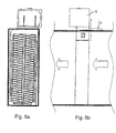
- the direction of the air flow is shown in Fig. 5b indicated by arrows.
- the ribs 9 increase the strength of the plastic frame 7.
- two slot-shaped openings 10th provided, which form a passage for the L-shaped contact plates 3.
- Projections 11 are provided, which the additional fixation of the arrangement serve in the plastic frame 7.
- the plastic frame 7 also has a portion 7 'arranged Tab 13, which means for attachment in an air duct a screw (not shown) is used (see Fig. 5b). Alternatively, the Attachment made for example by means of a clip connection.
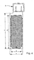
- the ratio of the free area which is about a x d corresponds to the total area b x c quite large, so that the pressure drop in the air duct is relatively low, so that a relatively low fan performance is required.
- a corresponds to the permeable width
- b the total width
- c the total length
- d the permeable length of the Heating arrangement 1 without plug 5.
- the ratio of a x d to b x c at approx. 84%.
- the heating arrangement with PTC element as decentralized Heater outside the air conditioner, for example, in appropriate Air ducts in the A-pillar, B-pillar, C-pillar or arranged in a door.
Landscapes
- Physics & Mathematics (AREA)
- Thermal Sciences (AREA)
- Engineering & Computer Science (AREA)
- Mechanical Engineering (AREA)
- Air-Conditioning For Vehicles (AREA)
- Resistance Heating (AREA)
- Direct Air Heating By Heater Or Combustion Gas (AREA)
Abstract
Description
- Fig. 1
- eine perspektivische Ansicht auf eine erfindungsgemäße Heizungsanordnung,
- Fig. 2
- eine andere perspektivische Ansicht auf die Heizungsanordnung von Fig. 1,
- Fig. 3
- die Heizungsanordnung von Fig. 1 in einer Explosionsdarstellung,
- Fig. 4
- eine Draufsicht auf die Heizungsanordnung von Fig. 1,
- Fig. 5a und 5b
- eine Darstellung der Integration in die Luftkanäle aus zwei verschiedenen Perspektiven,
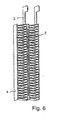
- Fig. 6
- eine perspektivische Ansicht eines Heizgitters mit PTC-Element ohne Rahmen, und
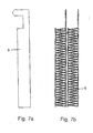
- Fig. 7a und 7b
- perspektivische Ansichten des Heizgitters von Fig. 6 ohne PTC-Element,
- 1
- Heizungsanordnung
- 2
- PTC-Element
- 3
- L-förmiges Kontaktblech
- 4
- Kontaktblech
- 5
- Stecker
- 6
- Wellrippe
- 7
- Kunststoff-Rahmen
- 7'
- Teil
- 7"
- Teil
- 8
- Clips-Verbindung
- 9
- Rippe
- 10
- Öffnung
- 11
- Vorsprung
- 12
- Vorsprung
- 13
- Lasche
Claims (15)
- Heizungsanordnung mit PTC-Element, insbesondere für ein Kraftfahrzeug, wobei um das PTC-Element (2) Wellrippen (6) für eine verbesserte Wärmeübertragung an einen die Heizungsanordnung (1) durchströmenden Luftstrom angeordnet sind, dadurch gekennzeichnet, dass die Heizungsanordnung (1) einen Kunststoff-Rahmen (7) aufweist, der zweiteilig ausgebildet ist.
- Heizungsanordnung nach Anspruch 1, dadurch gekennzeichnet, dass die beiden Teile (7', 7") des Kunststoff-Rahmens (7) mittels einer Clips-Verbindung (8) miteinander verbunden sind.
- Heizungsanordnung nach Anspruch 1 oder 2, dadurch gekennzeichnet, dass der Kunststoff-Rahmen (7) mindestens eine Öffnung (10) für zwei Kontaktbleche (3) aufweist und in der Nähe der Öffnung bzw. der Öffnungen (10) als Stecker (5) ausgebildet ist.
- Heizungsanordnung nach Anspruch 3, dadurch gekennzeichnet, dass der Stecker (5) in einem rechten Winkel zu den den elektrischen Kontakt herstellenden Kontaktblechen (3) ausgebildet ist, wobei ein Kabel und der Stecker (5) parallel zur Richtung des Luftstromes ausgerichtet sind.
- Heizungsanordnung einem der vorhergehenden Ansprüche, dadurch gekennzeichnet, dass auf beiden Seiten des PTC-Elements (2) Kontaktbleche (3, 4) angebracht sind.
- Heizungsanordnung einem der vorhergehenden Ansprüche, dadurch gekennzeichnet, dass das PTC-Element (2) an einem Kontaktblech (3, 4) mittels einer Klebe-Verbindung angebracht ist.
- Heizungsanordnung einem der vorhergehenden Ansprüche, dadurch gekennzeichnet, dass auf der dem PTC-Element (2) abgewandten Seite des Kontaktblechs (3, 4) eine Wellrippe (6) mittels einer Klebe-Verbindung angebracht ist.
- Heizungsanordnung nach einem der vorhergehenden Ansprüche, dadurch gekennzeichnet, dass auf der dem PTC-Element (2) abgewandten Seite der Wellrippe (6) ein weiteres Kontaktblech (4, 3) mittels einer Klebe-Verbindung an der Wellrippe (6) angebracht ist.
- Heizungsanordnung nach einem der vorhergehenden Ansprüche, dadurch gekennzeichnet, dass zwei Kontaktbleche (3) derart ausgebildet sind, dass sie an ihrem einen Ende als Teil eines Steckers (5) ausgebildet sind.
- Heizungsanordnung nach Anspruch 9, dadurch gekennzeichnet, dass die beiden Kontaktbleche (3) L-förmig ausgebildet sind.
- Heizungsanordnung nach einem der vorhergehenden Ansprüche, dadurch gekennzeichnet, dass der Rahmen eine Lasche (13) zur Anbringung der Heizungsanordnung (1) in oder an einem Luftkanal aufweist.
- Heizungsanordnung nach einem der Ansprüche, dadurch gekennzeichnet, dass der Rahmen (7) auf der Innenseite in Richtung des Luftstromes verlaufenden Rippen (9) aufweist.
- Heizungsanordnung nach einem der vorherigen Ansprüche, dadurch gekennzeichnet, dass die Heizungsanordnung als dezentraler Zuheizer ausgeführt ist, der in einem Luftkanal außerhalb eines Klimagerätes angeordnet ist.
- Heizungsanordnung nach einem der Ansprüche 5, 7 oder 8, dadurch gekennzeichnet, dass die Klebe-Verbindung durch einen Zwei-Komponenten-Silikon-Klebstoff gebildet ist.
- Heizungsanordnung nach einem der vorherigen Ansprüche, dadurch gekennzeichnet, dass die Heizungsanordnung durch Relais oder Regler gesteuert wird.
Priority Applications (4)
| Application Number | Priority Date | Filing Date | Title |
|---|---|---|---|
| AT03291428T ATE370008T1 (de) | 2003-06-13 | 2003-06-13 | Heizungsanordnung mit ptc-element, insbesondere für ein kraftfahrzeug |
| DE50307959T DE50307959D1 (de) | 2003-06-13 | 2003-06-13 | Heizungsanordnung mit PTC-Element, insbesondere für ein Kraftfahrzeug |
| EP03291428A EP1486363B1 (de) | 2003-06-13 | 2003-06-13 | Heizungsanordnung mit PTC-Element, insbesondere für ein Kraftfahrzeug |
| PT03291428T PT1486363E (pt) | 2003-06-13 | 2003-06-13 | Instalação de aquecimento com um elemento ptc, principalmente para um veículo motorizado |
Applications Claiming Priority (1)
| Application Number | Priority Date | Filing Date | Title |
|---|---|---|---|
| EP03291428A EP1486363B1 (de) | 2003-06-13 | 2003-06-13 | Heizungsanordnung mit PTC-Element, insbesondere für ein Kraftfahrzeug |
Publications (2)
| Publication Number | Publication Date |
|---|---|
| EP1486363A1 true EP1486363A1 (de) | 2004-12-15 |
| EP1486363B1 EP1486363B1 (de) | 2007-08-15 |
Family
ID=33185998
Family Applications (1)
| Application Number | Title | Priority Date | Filing Date |
|---|---|---|---|
| EP03291428A Revoked EP1486363B1 (de) | 2003-06-13 | 2003-06-13 | Heizungsanordnung mit PTC-Element, insbesondere für ein Kraftfahrzeug |
Country Status (4)
| Country | Link |
|---|---|
| EP (1) | EP1486363B1 (de) |
| AT (1) | ATE370008T1 (de) |
| DE (1) | DE50307959D1 (de) |
| PT (1) | PT1486363E (de) |
Cited By (4)
| Publication number | Priority date | Publication date | Assignee | Title |
|---|---|---|---|---|
| FR2944395A1 (fr) * | 2009-04-10 | 2010-10-15 | Valeo Systemes Thermiques | Armature pour un module chauffant electrique |
| US7977605B2 (en) | 2003-10-07 | 2011-07-12 | Behr France Rouffach Sas | Heating assembly comprising a PTC element, in particular for a motor vehicle |
| WO2018073530A1 (fr) | 2016-10-21 | 2018-04-26 | Valeo Systemes Thermiques | Dispositif de chauffage additionnel electrique |
| US10363797B2 (en) | 2013-06-03 | 2019-07-30 | Borgwarner Ludwigsburg Gmbh | Vehicle heater |
Citations (3)
| Publication number | Priority date | Publication date | Assignee | Title |
|---|---|---|---|---|
| EP0705055A2 (de) * | 1994-09-28 | 1996-04-03 | Behr GmbH & Co. | Elektrische Heizeinrichtung, insbesondere für ein Kraftfahrzeug |
| EP0901311A2 (de) * | 1997-09-02 | 1999-03-10 | Behr GmbH & Co. | Elektrische Heizeinrichtung, insbesondere für ein Kraftfahrzeug |
| EP1061776A1 (de) * | 1999-06-15 | 2000-12-20 | David & Baader DBK Spezialfabrik elektrischer Apparate und Heizwiderstände GmbH | Heizvorrichtung zur Lufterwärmung |
-
2003
- 2003-06-13 AT AT03291428T patent/ATE370008T1/de not_active IP Right Cessation
- 2003-06-13 PT PT03291428T patent/PT1486363E/pt unknown
- 2003-06-13 DE DE50307959T patent/DE50307959D1/de not_active Expired - Lifetime
- 2003-06-13 EP EP03291428A patent/EP1486363B1/de not_active Revoked
Patent Citations (3)
| Publication number | Priority date | Publication date | Assignee | Title |
|---|---|---|---|---|
| EP0705055A2 (de) * | 1994-09-28 | 1996-04-03 | Behr GmbH & Co. | Elektrische Heizeinrichtung, insbesondere für ein Kraftfahrzeug |
| EP0901311A2 (de) * | 1997-09-02 | 1999-03-10 | Behr GmbH & Co. | Elektrische Heizeinrichtung, insbesondere für ein Kraftfahrzeug |
| EP1061776A1 (de) * | 1999-06-15 | 2000-12-20 | David & Baader DBK Spezialfabrik elektrischer Apparate und Heizwiderstände GmbH | Heizvorrichtung zur Lufterwärmung |
Cited By (9)
| Publication number | Priority date | Publication date | Assignee | Title |
|---|---|---|---|---|
| US7977605B2 (en) | 2003-10-07 | 2011-07-12 | Behr France Rouffach Sas | Heating assembly comprising a PTC element, in particular for a motor vehicle |
| FR2944395A1 (fr) * | 2009-04-10 | 2010-10-15 | Valeo Systemes Thermiques | Armature pour un module chauffant electrique |
| EP2241840A1 (de) * | 2009-04-10 | 2010-10-20 | Valeo Systèmes Thermiques | Rahmen für ein elektrisches Heizmodul und zugehoeriges Herstellungsverfahren |
| CN101913312A (zh) * | 2009-04-10 | 2010-12-15 | 法雷奥热系统公司 | 用于电加热组件的骨架 |
| CN101913312B (zh) * | 2009-04-10 | 2015-06-03 | 法雷奥热系统公司 | 用于电加热组件的骨架 |
| US10363797B2 (en) | 2013-06-03 | 2019-07-30 | Borgwarner Ludwigsburg Gmbh | Vehicle heater |
| WO2018073530A1 (fr) | 2016-10-21 | 2018-04-26 | Valeo Systemes Thermiques | Dispositif de chauffage additionnel electrique |
| KR20190056403A (ko) | 2016-10-21 | 2019-05-24 | 발레오 시스템므 떼르미끄 | 전기식 보조 가열 장치 |
| US11214123B2 (en) | 2016-10-21 | 2022-01-04 | Valeo Systemes Thermiques | Electric auxiliary heating device |
Also Published As
| Publication number | Publication date |
|---|---|
| DE50307959D1 (de) | 2007-09-27 |
| PT1486363E (pt) | 2007-11-09 |
| EP1486363B1 (de) | 2007-08-15 |
| ATE370008T1 (de) | 2007-09-15 |
Similar Documents
| Publication | Publication Date | Title |
|---|---|---|
| EP1523226B1 (de) | Heizungsanordnung mit PTC-Element, insbesondere für ein Kraftfahrzeug | |
| EP2017548B1 (de) | Elektrische Heizvorrichtung insbesondere für Kraftfahrzeuge | |
| EP1800520B1 (de) | Elektrische heizungsanordnung, insbesondere für ein kraftfahrzeug | |
| EP3313679A1 (de) | Klimaanlage für ein fahrzeug, insbesondere aufdachklimaanlage und fahrzeug mit einer solchen klimaanlage | |
| DE102010010399A1 (de) | Lüftungsdüse für den Fahrzeuginnenraum | |
| DE4434613A1 (de) | Elektrische Heizeinrichtung, insbesondere für ein Kraftfahrzeug | |
| DE69725667T2 (de) | Fahrzeugheizgerät | |
| EP1621378B2 (de) | Heizungsanordnung mit einem Heizelement, insbesondere für ein Kraftfahrzeug | |
| DE102013000628B4 (de) | Halterahmen einer Frischluftklappe eines Kraftfahrzeuges sowie Frischluftklappe mit Halterahmen | |
| EP1641642B1 (de) | Kraftfahrzeug-klimaanlage | |
| EP1731340B1 (de) | Elektrische Heizeinrichtung | |
| EP1522439B2 (de) | Heizungsanordnung mit PTC-Element, insbesondere für ein Kraftfahrzeug | |
| EP1486363B1 (de) | Heizungsanordnung mit PTC-Element, insbesondere für ein Kraftfahrzeug | |
| DE10256619B3 (de) | Klimagerät für Fahrzeuge | |
| EP1621826B1 (de) | Heizungsanordnung mit PTC-Element, insbesondere für ein Kraftfahrzeug | |
| EP1652704B1 (de) | Elektrische Heizungsanordnung, inbesondere für ein Kraftfahrzeug | |
| EP1652703B2 (de) | Elektrische Heizungsanordnung für ein Kraftfahrzeug | |
| EP1521499A1 (de) | Steckanordnung für eine Heizungsanordnung mit PTC-Elementen, insbesondere für ein Kraftfahrzeug | |
| DE10125367A1 (de) | Klimaanlage mit einer Einheiten-Verbindungsstruktur | |
| EP1561615B1 (de) | Vorrichtung zum Austausch von Wärme | |
| EP3511645B1 (de) | Elektrische heizvorrichtung | |
| WO2007113078A1 (de) | Abdeckung eines elektrischen aggregats eines kraftfahrzeugs | |
| DE102008007914A1 (de) | Deckel-Gehäuse-Anordnung, insbesondere für einen Filter einer Fahrzeug-Klimaanlage | |
| DE102017121423A1 (de) | Belüftungsvorrichtung für ein Fahrzeug | |
| DE102004056593A1 (de) | Halteranordnung |
Legal Events
| Date | Code | Title | Description |
|---|---|---|---|
| PUAI | Public reference made under article 153(3) epc to a published international application that has entered the european phase |
Free format text: ORIGINAL CODE: 0009012 |
|
| AK | Designated contracting states |
Kind code of ref document: A1 Designated state(s): AT BE BG CH CY CZ DE DK EE ES FI FR GB GR HU IE IT LI LU MC NL PT RO SE SI SK TR |
|
| AX | Request for extension of the european patent |
Extension state: AL LT LV MK |
|
| 17P | Request for examination filed |
Effective date: 20050615 |
|
| AKX | Designation fees paid |
Designated state(s): AT BE BG CH CY CZ DE DK EE ES FI FR GB GR HU IE IT LI LU MC NL PT RO SE SI SK TR |
|
| RAP1 | Party data changed (applicant data changed or rights of an application transferred) |
Owner name: BEHR FRANCE ROUFFACH SAS |
|
| 17Q | First examination report despatched |
Effective date: 20060217 |
|
| GRAP | Despatch of communication of intention to grant a patent |
Free format text: ORIGINAL CODE: EPIDOSNIGR1 |
|
| GRAS | Grant fee paid |
Free format text: ORIGINAL CODE: EPIDOSNIGR3 |
|
| GRAA | (expected) grant |
Free format text: ORIGINAL CODE: 0009210 |
|
| AK | Designated contracting states |
Kind code of ref document: B1 Designated state(s): AT BE BG CH CY CZ DE DK EE ES FI FR GB GR HU IE IT LI LU MC NL PT RO SE SI SK TR |
|
| REG | Reference to a national code |
Ref country code: GB Ref legal event code: FG4D Free format text: NOT ENGLISH |
|
| REG | Reference to a national code |
Ref country code: CH Ref legal event code: EP |
|
| REG | Reference to a national code |
Ref country code: IE Ref legal event code: FG4D Free format text: LANGUAGE OF EP DOCUMENT: GERMAN |
|
| REF | Corresponds to: |
Ref document number: 50307959 Country of ref document: DE Date of ref document: 20070927 Kind code of ref document: P |
|
| REG | Reference to a national code |
Ref country code: SE Ref legal event code: TRGR |
|
| REG | Reference to a national code |
Ref country code: PT Ref legal event code: SC4A Free format text: AVAILABILITY OF NATIONAL TRANSLATION Effective date: 20071029 |
|
| PG25 | Lapsed in a contracting state [announced via postgrant information from national office to epo] |
Ref country code: NL Free format text: LAPSE BECAUSE OF FAILURE TO SUBMIT A TRANSLATION OF THE DESCRIPTION OR TO PAY THE FEE WITHIN THE PRESCRIBED TIME-LIMIT Effective date: 20070815 Ref country code: ES Free format text: LAPSE BECAUSE OF FAILURE TO SUBMIT A TRANSLATION OF THE DESCRIPTION OR TO PAY THE FEE WITHIN THE PRESCRIBED TIME-LIMIT Effective date: 20071126 Ref country code: FI Free format text: LAPSE BECAUSE OF FAILURE TO SUBMIT A TRANSLATION OF THE DESCRIPTION OR TO PAY THE FEE WITHIN THE PRESCRIBED TIME-LIMIT Effective date: 20070815 Ref country code: BG Free format text: LAPSE BECAUSE OF FAILURE TO SUBMIT A TRANSLATION OF THE DESCRIPTION OR TO PAY THE FEE WITHIN THE PRESCRIBED TIME-LIMIT Effective date: 20071115 |
|
| NLV1 | Nl: lapsed or annulled due to failure to fulfill the requirements of art. 29p and 29m of the patents act | ||
| GBV | Gb: ep patent (uk) treated as always having been void in accordance with gb section 77(7)/1977 [no translation filed] |
Effective date: 20070815 |
|
| ET | Fr: translation filed | ||
| REG | Reference to a national code |
Ref country code: IE Ref legal event code: FD4D |
|
| PG25 | Lapsed in a contracting state [announced via postgrant information from national office to epo] |
Ref country code: GR Free format text: LAPSE BECAUSE OF FAILURE TO SUBMIT A TRANSLATION OF THE DESCRIPTION OR TO PAY THE FEE WITHIN THE PRESCRIBED TIME-LIMIT Effective date: 20071116 Ref country code: DK Free format text: LAPSE BECAUSE OF FAILURE TO SUBMIT A TRANSLATION OF THE DESCRIPTION OR TO PAY THE FEE WITHIN THE PRESCRIBED TIME-LIMIT Effective date: 20070815 |
|
| PLBI | Opposition filed |
Free format text: ORIGINAL CODE: 0009260 |
|
| PG25 | Lapsed in a contracting state [announced via postgrant information from national office to epo] |
Ref country code: SK Free format text: LAPSE BECAUSE OF FAILURE TO SUBMIT A TRANSLATION OF THE DESCRIPTION OR TO PAY THE FEE WITHIN THE PRESCRIBED TIME-LIMIT Effective date: 20070815 Ref country code: IE Free format text: LAPSE BECAUSE OF FAILURE TO SUBMIT A TRANSLATION OF THE DESCRIPTION OR TO PAY THE FEE WITHIN THE PRESCRIBED TIME-LIMIT Effective date: 20070815 Ref country code: GB Free format text: LAPSE BECAUSE OF FAILURE TO SUBMIT A TRANSLATION OF THE DESCRIPTION OR TO PAY THE FEE WITHIN THE PRESCRIBED TIME-LIMIT Effective date: 20070815 |
|
| 26 | Opposition filed |
Opponent name: BERU AG Effective date: 20080514 Opponent name: CATEM GMBH & CO. KG Effective date: 20080514 |
|
| PG25 | Lapsed in a contracting state [announced via postgrant information from national office to epo] |
Ref country code: RO Free format text: LAPSE BECAUSE OF FAILURE TO SUBMIT A TRANSLATION OF THE DESCRIPTION OR TO PAY THE FEE WITHIN THE PRESCRIBED TIME-LIMIT Effective date: 20070815 |
|
| PLAN | Information deleted related to communication of a notice of opposition and request to file observations + time limit |
Free format text: ORIGINAL CODE: EPIDOSDOBS2 |
|
| PLAX | Notice of opposition and request to file observation + time limit sent |
Free format text: ORIGINAL CODE: EPIDOSNOBS2 |
|
| PLAX | Notice of opposition and request to file observation + time limit sent |
Free format text: ORIGINAL CODE: EPIDOSNOBS2 |
|
| PLBB | Reply of patent proprietor to notice(s) of opposition received |
Free format text: ORIGINAL CODE: EPIDOSNOBS3 |
|
| PLAB | Opposition data, opponent's data or that of the opponent's representative modified |
Free format text: ORIGINAL CODE: 0009299OPPO |
|
| BERE | Be: lapsed |
Owner name: BEHR FRANCE ROUFFACH SAS Effective date: 20080630 |
|
| R26 | Opposition filed (corrected) |
Opponent name: CATEM GMBH & CO. KG Effective date: 20080514 Opponent name: BERU AG Effective date: 20080514 |
|
| PG25 | Lapsed in a contracting state [announced via postgrant information from national office to epo] |
Ref country code: MC Free format text: LAPSE BECAUSE OF NON-PAYMENT OF DUE FEES Effective date: 20080630 |
|
| REG | Reference to a national code |
Ref country code: CH Ref legal event code: PL |
|
| PG25 | Lapsed in a contracting state [announced via postgrant information from national office to epo] |
Ref country code: BE Free format text: LAPSE BECAUSE OF NON-PAYMENT OF DUE FEES Effective date: 20080630 |
|
| PG25 | Lapsed in a contracting state [announced via postgrant information from national office to epo] |
Ref country code: EE Free format text: LAPSE BECAUSE OF FAILURE TO SUBMIT A TRANSLATION OF THE DESCRIPTION OR TO PAY THE FEE WITHIN THE PRESCRIBED TIME-LIMIT Effective date: 20070815 |
|
| PG25 | Lapsed in a contracting state [announced via postgrant information from national office to epo] |
Ref country code: CH Free format text: LAPSE BECAUSE OF NON-PAYMENT OF DUE FEES Effective date: 20080630 Ref country code: SI Free format text: LAPSE BECAUSE OF FAILURE TO SUBMIT A TRANSLATION OF THE DESCRIPTION OR TO PAY THE FEE WITHIN THE PRESCRIBED TIME-LIMIT Effective date: 20070815 Ref country code: LI Free format text: LAPSE BECAUSE OF NON-PAYMENT OF DUE FEES Effective date: 20080630 |
|
| PG25 | Lapsed in a contracting state [announced via postgrant information from national office to epo] |
Ref country code: CY Free format text: LAPSE BECAUSE OF FAILURE TO SUBMIT A TRANSLATION OF THE DESCRIPTION OR TO PAY THE FEE WITHIN THE PRESCRIBED TIME-LIMIT Effective date: 20070815 |
|
| PG25 | Lapsed in a contracting state [announced via postgrant information from national office to epo] |
Ref country code: AT Free format text: LAPSE BECAUSE OF NON-PAYMENT OF DUE FEES Effective date: 20080613 |
|
| RDAF | Communication despatched that patent is revoked |
Free format text: ORIGINAL CODE: EPIDOSNREV1 |
|
| PG25 | Lapsed in a contracting state [announced via postgrant information from national office to epo] |
Ref country code: LU Free format text: LAPSE BECAUSE OF NON-PAYMENT OF DUE FEES Effective date: 20080613 Ref country code: HU Free format text: LAPSE BECAUSE OF FAILURE TO SUBMIT A TRANSLATION OF THE DESCRIPTION OR TO PAY THE FEE WITHIN THE PRESCRIBED TIME-LIMIT Effective date: 20080216 |
|
| PGFP | Annual fee paid to national office [announced via postgrant information from national office to epo] |
Ref country code: PT Payment date: 20100611 Year of fee payment: 8 |
|
| PG25 | Lapsed in a contracting state [announced via postgrant information from national office to epo] |
Ref country code: TR Free format text: LAPSE BECAUSE OF FAILURE TO SUBMIT A TRANSLATION OF THE DESCRIPTION OR TO PAY THE FEE WITHIN THE PRESCRIBED TIME-LIMIT Effective date: 20070815 |
|
| APBM | Appeal reference recorded |
Free format text: ORIGINAL CODE: EPIDOSNREFNO |
|
| APBP | Date of receipt of notice of appeal recorded |
Free format text: ORIGINAL CODE: EPIDOSNNOA2O |
|
| APAH | Appeal reference modified |
Free format text: ORIGINAL CODE: EPIDOSCREFNO |
|
| APBQ | Date of receipt of statement of grounds of appeal recorded |
Free format text: ORIGINAL CODE: EPIDOSNNOA3O |
|
| PLAB | Opposition data, opponent's data or that of the opponent's representative modified |
Free format text: ORIGINAL CODE: 0009299OPPO |
|
| R26 | Opposition filed (corrected) |
Opponent name: CATEM GMBH & CO. KG Effective date: 20080514 Opponent name: BORGWARNER BERU SYSTEMS GMBH Effective date: 20080514 |
|
| REG | Reference to a national code |
Ref country code: PT Ref legal event code: MM4A Free format text: LAPSE DUE TO NON-PAYMENT OF FEES Effective date: 20111213 |
|
| PG25 | Lapsed in a contracting state [announced via postgrant information from national office to epo] |
Ref country code: PT Free format text: LAPSE BECAUSE OF NON-PAYMENT OF DUE FEES Effective date: 20111213 |
|
| PGFP | Annual fee paid to national office [announced via postgrant information from national office to epo] |
Ref country code: CZ Payment date: 20120607 Year of fee payment: 10 |
|
| PGFP | Annual fee paid to national office [announced via postgrant information from national office to epo] |
Ref country code: IT Payment date: 20120621 Year of fee payment: 10 |
|
| PG25 | Lapsed in a contracting state [announced via postgrant information from national office to epo] |
Ref country code: CZ Free format text: LAPSE BECAUSE OF NON-PAYMENT OF DUE FEES Effective date: 20130613 |
|
| PGFP | Annual fee paid to national office [announced via postgrant information from national office to epo] |
Ref country code: DE Payment date: 20131125 Year of fee payment: 11 Ref country code: FR Payment date: 20131122 Year of fee payment: 11 Ref country code: SE Payment date: 20131122 Year of fee payment: 11 |
|
| REG | Reference to a national code |
Ref country code: DE Ref legal event code: R103 Ref document number: 50307959 Country of ref document: DE Ref country code: DE Ref legal event code: R064 Ref document number: 50307959 Country of ref document: DE |
|
| APBU | Appeal procedure closed |
Free format text: ORIGINAL CODE: EPIDOSNNOA9O |
|
| RDAG | Patent revoked |
Free format text: ORIGINAL CODE: 0009271 |
|
| STAA | Information on the status of an ep patent application or granted ep patent |
Free format text: STATUS: PATENT REVOKED |
|
| 27W | Patent revoked |
Effective date: 20140206 |
|
| PG25 | Lapsed in a contracting state [announced via postgrant information from national office to epo] |
Ref country code: IT Free format text: LAPSE BECAUSE OF NON-PAYMENT OF DUE FEES Effective date: 20130613 |
|
| REG | Reference to a national code |
Ref country code: DE Ref legal event code: R107 Ref document number: 50307959 Country of ref document: DE Effective date: 20140618 |
|
| REG | Reference to a national code |
Ref country code: AT Ref legal event code: MA03 Ref document number: 370008 Country of ref document: AT Kind code of ref document: T Effective date: 20140206 |
|
| REG | Reference to a national code |
Ref country code: SE Ref legal event code: ECNC |
|
| REG | Reference to a national code |
Ref country code: SE Ref legal event code: ECNC |