EP1486298A1 - Robot, controleur de robot a jambes et procede correspondant, systeme de capteurs pour robot a jambes, et appareil locomoteur - Google Patents
Robot, controleur de robot a jambes et procede correspondant, systeme de capteurs pour robot a jambes, et appareil locomoteur Download PDFInfo
- Publication number
- EP1486298A1 EP1486298A1 EP03710407A EP03710407A EP1486298A1 EP 1486298 A1 EP1486298 A1 EP 1486298A1 EP 03710407 A EP03710407 A EP 03710407A EP 03710407 A EP03710407 A EP 03710407A EP 1486298 A1 EP1486298 A1 EP 1486298A1
- Authority
- EP
- European Patent Office
- Prior art keywords
- gravity
- center
- robot
- sensor
- acceleration
- Prior art date
- Legal status (The legal status is an assumption and is not a legal conclusion. Google has not performed a legal analysis and makes no representation as to the accuracy of the status listed.)
- Granted
Links
- 230000033001 locomotion Effects 0.000 title claims description 266
- 238000000034 method Methods 0.000 title claims description 55
- 230000001133 acceleration Effects 0.000 claims abstract description 239
- 238000006243 chemical reaction Methods 0.000 claims abstract description 22
- 230000005484 gravity Effects 0.000 claims description 135
- 238000004364 calculation method Methods 0.000 claims description 49
- 210000001364 upper extremity Anatomy 0.000 claims description 18
- 210000003141 lower extremity Anatomy 0.000 claims description 16
- 238000005259 measurement Methods 0.000 claims description 9
- 238000012937 correction Methods 0.000 claims description 7
- 238000001514 detection method Methods 0.000 claims description 3
- 210000002683 foot Anatomy 0.000 description 58
- 210000001624 hip Anatomy 0.000 description 27
- 241000282414 Homo sapiens Species 0.000 description 26
- 210000002414 leg Anatomy 0.000 description 19
- 238000013519 translation Methods 0.000 description 19
- 210000004394 hip joint Anatomy 0.000 description 13
- 238000012545 processing Methods 0.000 description 12
- 230000009471 action Effects 0.000 description 10
- 210000004247 hand Anatomy 0.000 description 10
- 210000003128 head Anatomy 0.000 description 10
- 210000001503 joint Anatomy 0.000 description 10
- 238000010276 construction Methods 0.000 description 8
- 230000004044 response Effects 0.000 description 7
- 210000000323 shoulder joint Anatomy 0.000 description 7
- 210000000544 articulatio talocruralis Anatomy 0.000 description 6
- 210000002310 elbow joint Anatomy 0.000 description 5
- 230000000087 stabilizing effect Effects 0.000 description 5
- 210000003423 ankle Anatomy 0.000 description 4
- 230000008859 change Effects 0.000 description 4
- 238000004891 communication Methods 0.000 description 4
- 210000003414 extremity Anatomy 0.000 description 4
- 210000000629 knee joint Anatomy 0.000 description 4
- 230000007246 mechanism Effects 0.000 description 4
- 230000008569 process Effects 0.000 description 4
- 230000006641 stabilisation Effects 0.000 description 4
- 238000011105 stabilization Methods 0.000 description 4
- 238000011161 development Methods 0.000 description 3
- 230000018109 developmental process Effects 0.000 description 3
- 230000003137 locomotive effect Effects 0.000 description 3
- 238000004519 manufacturing process Methods 0.000 description 3
- 230000003278 mimic effect Effects 0.000 description 3
- 238000011160 research Methods 0.000 description 3
- 210000000689 upper leg Anatomy 0.000 description 3
- 210000003857 wrist joint Anatomy 0.000 description 3
- 230000000052 comparative effect Effects 0.000 description 2
- 238000006073 displacement reaction Methods 0.000 description 2
- 230000000694 effects Effects 0.000 description 2
- 210000000245 forearm Anatomy 0.000 description 2
- 230000006870 function Effects 0.000 description 2
- 239000011521 glass Substances 0.000 description 2
- 230000001788 irregular Effects 0.000 description 2
- 230000009191 jumping Effects 0.000 description 2
- 210000003127 knee Anatomy 0.000 description 2
- 230000002093 peripheral effect Effects 0.000 description 2
- 238000012546 transfer Methods 0.000 description 2
- 210000000707 wrist Anatomy 0.000 description 2
- 241000282693 Cercopithecidae Species 0.000 description 1
- 241001465754 Metazoa Species 0.000 description 1
- RAQQRQCODVNJCK-JLHYYAGUSA-N N-[(4-amino-2-methylpyrimidin-5-yl)methyl]-N-[(E)-5-hydroxy-3-(2-hydroxyethyldisulfanyl)pent-2-en-2-yl]formamide Chemical compound C\C(N(Cc1cnc(C)nc1N)C=O)=C(\CCO)SSCCO RAQQRQCODVNJCK-JLHYYAGUSA-N 0.000 description 1
- 230000003044 adaptive effect Effects 0.000 description 1
- 230000004888 barrier function Effects 0.000 description 1
- 230000006399 behavior Effects 0.000 description 1
- 230000008901 benefit Effects 0.000 description 1
- 230000007321 biological mechanism Effects 0.000 description 1
- 230000008878 coupling Effects 0.000 description 1
- 238000010168 coupling process Methods 0.000 description 1
- 238000005859 coupling reaction Methods 0.000 description 1
- 238000013016 damping Methods 0.000 description 1
- 230000003247 decreasing effect Effects 0.000 description 1
- 230000001419 dependent effect Effects 0.000 description 1
- 238000013461 design Methods 0.000 description 1
- 238000010586 diagram Methods 0.000 description 1
- 230000004069 differentiation Effects 0.000 description 1
- 238000005516 engineering process Methods 0.000 description 1
- 210000001061 forehead Anatomy 0.000 description 1
- 238000011089 mechanical engineering Methods 0.000 description 1
- 230000015654 memory Effects 0.000 description 1
- 230000010399 physical interaction Effects 0.000 description 1
- 230000002265 prevention Effects 0.000 description 1
- 238000012827 research and development Methods 0.000 description 1
- 230000001020 rhythmical effect Effects 0.000 description 1
- 230000035939 shock Effects 0.000 description 1
Images


Classifications
-
- B—PERFORMING OPERATIONS; TRANSPORTING
- B62—LAND VEHICLES FOR TRAVELLING OTHERWISE THAN ON RAILS
- B62D—MOTOR VEHICLES; TRAILERS
- B62D57/00—Vehicles characterised by having other propulsion or other ground- engaging means than wheels or endless track, alone or in addition to wheels or endless track
- B62D57/02—Vehicles characterised by having other propulsion or other ground- engaging means than wheels or endless track, alone or in addition to wheels or endless track with ground-engaging propulsion means, e.g. walking members
-
- B—PERFORMING OPERATIONS; TRANSPORTING
- B25—HAND TOOLS; PORTABLE POWER-DRIVEN TOOLS; MANIPULATORS
- B25J—MANIPULATORS; CHAMBERS PROVIDED WITH MANIPULATION DEVICES
- B25J13/00—Controls for manipulators
- B25J13/08—Controls for manipulators by means of sensing devices, e.g. viewing or touching devices
- B25J13/085—Force or torque sensors
-
- B—PERFORMING OPERATIONS; TRANSPORTING
- B25—HAND TOOLS; PORTABLE POWER-DRIVEN TOOLS; MANIPULATORS
- B25J—MANIPULATORS; CHAMBERS PROVIDED WITH MANIPULATION DEVICES
- B25J13/00—Controls for manipulators
- B25J13/08—Controls for manipulators by means of sensing devices, e.g. viewing or touching devices
- B25J13/088—Controls for manipulators by means of sensing devices, e.g. viewing or touching devices with position, velocity or acceleration sensors
-
- B—PERFORMING OPERATIONS; TRANSPORTING
- B62—LAND VEHICLES FOR TRAVELLING OTHERWISE THAN ON RAILS
- B62D—MOTOR VEHICLES; TRAILERS
- B62D57/00—Vehicles characterised by having other propulsion or other ground- engaging means than wheels or endless track, alone or in addition to wheels or endless track
- B62D57/02—Vehicles characterised by having other propulsion or other ground- engaging means than wheels or endless track, alone or in addition to wheels or endless track with ground-engaging propulsion means, e.g. walking members
- B62D57/032—Vehicles characterised by having other propulsion or other ground- engaging means than wheels or endless track, alone or in addition to wheels or endless track with ground-engaging propulsion means, e.g. walking members with alternately or sequentially lifted supporting base and legs; with alternately or sequentially lifted feet or skid
Definitions
- the present invention generally relates to a movement controlling apparatus and method for a legged locomotion robot having at least a plurality of moving legs, a sensor system for a legged locomotion robot, and a mobile device, and more particularly to a movement controlling apparatus and method for a legged locomotion robot, in which a ZMP (zero-moment point) is adopted as a stability criterion, a sensor system for a legged locomotion robot, and a mobile device.
- a ZMP zero-moment point
- the present invention is directed to a movement controlling apparatus and method for a legged locomotion robot, in which a ZMP equation introduced based on measurements from sensors mounted at various portions of a robot is used to identify an unknown external force moment and unknown external force for controlling the movement of the robot, a sensor system for a legged locomotion robot, and a mobile device, and more particularly to a movement controlling apparatus and method for a legged locomotion robot, in which a sensor system including sensors distributed on various portions of the robot is used to effectively measure movement parameters required for introduction of the ZMP equation, a sensor system for a legged locomotion robot, and a mobile device.
- robot A mechanical apparatus designed based on the electrical and magnetic engineering to mimic human movements is called “robot”.
- the term “robot” is said to have been derived from a Slavic word “ROBOTA (slave machine)".
- ROBOTA slave machine
- the robots have become more widely prevalent at the end of 1960s.
- Many of such robots were industrial ones such as the manipulators and conveyance robots destined for automation and unmanning of the production operations in factories.
- the bipedal movement in an upright posture is more unstable and difficult to control in attitude and walking than the movements on crawlers, four or six feet.
- the bipedal upright movement is more advantageous in the flexible movement over irregular ground surfaces, irregular access routes on which there exist obstacles, and stepped surfaces such as a stepway or ladder.
- the legged locomotive robots designed to implement the biological mechanism and movements of the human being is generally called “humanoid robot".
- the humanoid robot can support the human activity in the residential environment and other daily life, for example.
- the mechanical systems or robots should desirably be able to move in nearly the same range as the human moving range. It is considerably expected just in this respect that the practical applicability of the robots can be attained.
- One of the viewpoints stands on the human science. That is, a robot designed to have a structure similar to the lower limb and/or upper limb of the human body is controlled in various manners to simulate the walking of the human being. By the engineering through such processes, it is possible to elucidate the mechanism of the human being's natural movements including the walking. The results of such researches will also have a great contribution to the advances of various other fields of researches dealing with the movement mechanism, such as the human engineering, rehabilitation engineering, sports science, etc.
- the other viewpoint is the development of practical robots capable of supporting the human life as a partner to the human being, namely, capable of helping the human being in activities in the residential environment and various other daily life situations.
- the robots of this type they should be designed to grow up in functional respects by learning, while being taught by the users, the addressing to the human beings different in personality from each other or to different environments in various aspects of the human life environment.
- the "humanoid" robots are considered to effectively perform well for smooth communications with the human being.
- attitude control and stable walking of the bipedal legged locomotion robots There have already been proposed many techniques for attitude control and stable walking of the bipedal legged locomotion robots.
- the "stable walking” referred to herein may be defined as "movement on feet without falling”.
- the control of the robot to take a stable attitude is very important to prevent the robot from falling.
- the "falling" means an interruption of a job the robot has been doing.
- the robot will take considerable labor and time to recover its upright position from the tipping condition and resume the job. Also, the falling will possibly cause a critical damage to the robot itself and also to an object with which the robot has collided in falling. Therefore, the control of the robot to take a stable posture in walking or working is one of the most important technical problems in designing and development of a legged locomotion robot.
- the bipedal walking robot such as "humanoid robot” has its center of gravity in a position higher than any quadrupedal walking robot, and it has a narrower ZMP region in which a ZMP is stable in walking. Therefore, the problem of posture change due to a change of the walking surface is important especially for the bipedal walking robot.
- the Japanese Patent Application Laid-Open No. H05-305579 discloses a legged locomotion robot in which an on-surface point where a ZMP is zero is made to coincide with the target value of attitude control for stable walking.
- the Japanese Patent Application Laid-Open No. H05-305581 discloses a legged locomotion robot designed for a ZMP to exist inside a supporting polygon or in a position where there is at least a predetermined margin from the end of a supporting polygon when the foot sole touches and leaves a walking surface. Since the ZMP keeps the predetermined margin even when the robot is applied with a disturbance, so the robot can walk with an improved stability.
- the Japanese Published Patent Application Laid-Open No. H05-305583 disclosed a legged locomotion robot in which the moving speed is controlled according to the target position of a ZMP. More specifically, preset walking pattern data is used to drive the leg joints for the ZMP to coincide with the target position, an inclination of the robot's upper body is detected, and the spit-out rate of the preset walking pattern data is changed correspondingly to the detected inclination.
- the robot stepping on unknown irregularities tilts forward the normal posture can be recovered by increasing the data spit-out rate.
- the ZMP since the ZMP is controlled to its target value, the data spit-out rate can be changed without any trouble while the robot is supported on both feet.
- the Japanese Published Patent Application Laid-Open No. H05-305585 disclosed a legged locomotion robot in which the position the foot sole touches is controlled according to a ZMP target position. More specifically, the disclosed legged locomotion robot can walk stably by detecting a displacement between the ZMP target position and measured position and driving one or both of the legs so that the displacement is canceled, or detecting a moment about the ZMP target position and driving the legs so that the moment becomes zero.
- the Japanese Published Patent Application Laid-Open No. H05-305586 discloses a legged locomotion robot of which inclined attitude is controlled according to a ZMP target position. More particularly, the robot walks stably by detecting a moment, if any, developed about the ZMP target position, and driving the legs so that the moment becomes zero.
- a ZMP equation descriptive of a balanced relation between moments applied to the robot body is derived and the target trajectory of the robot is corrected to cancel a moment error appearing in the ZMP equation.
- a ZMP equation For formulating a ZMP equation, it is necessary to determine a position and acceleration of a controlled-object point on the robot.
- a ZMP equation is derived by calculating acceleration data through two-step differentiation of the position data in the control system with data on the position of the controlled-object point being taken as sensor input.
- the movement of the mobile machines including the legged robot is strictly controlled according to a ZMP equation, for example.
- the most strict control of the robot movement will be attained by controlling the position and acceleration of each point on the robot with measurement of an acceleration in a world coordinate of the origin of a local coordinate, position (posture) and acceleration of each point on the robot in the local coordinate, ZMP position, external force and external force moment, and introduction of the measured values in the ZMP equation to identify an unknown external force moment and external force.
- the robot movement can be controlled with a minimum number of sensors including a clinometer (or accelerometer) and gyro provided on each axis (pitch, roll and yaw (X, Y and Z)) and six axial-force sensors disposed each at a point it is expected an external force and external force moment are applied to and which is apart from an actual position of action.
- a clinometer or accelerometer
- gyro provided on each axis
- axial-force sensors disposed each at a point it is expected an external force and external force moment are applied to and which is apart from an actual position of action.
- the present invention has an object to overcome the above-mentioned drawbacks of the related art by providing an improved and novel movement controlling device and method for a legged locomotion robot, capable of making, based on a ZMP as a posture-stability criterion, a control for stabilization of the robot posture in moving.
- Another object of the present invention is to provide an improved and novel movement controlling device and method for a legged locomotion robot, capable of strictly controlling the robot to take a stable posture by deriving a ZMP equation quickly and with a high accuracy.
- Still another object of the present invention is to provide an improved and novel movement controlling device and method and an improved and novel sensor system for the legged locomotion robot, capable of well controlling, based on a ZMP as a posture-stability criterion, the robot to take a stable posture.
- Yet another object of the present invention is to provide an improved and novel movement controlling device and method for a legged locomotion robot, and an improved and novel sensor system for the legged locomotion robot, capable of well controlling the robot movement by identifying an unknown external force moment and unknown external force using a ZMP equation introduced based on measured values from sensors provided at various points on the robot.
- Still yet another object of the present invention is to provide an improved and novel movement controlling device and method for a legged locomotion robot, and an improved and novel sensor system for the legged locomotion robot, capable of efficiently measuring movement parameters required for introduction of a ZMP equation by a system of sensors distributed at various points on the robot.
- the above object can be attained by providing a robot device including a basic unit and a plurality of moving units connected to the basic unit, the device including according to the present invention:
- the robot movement has to be controlled by introducing an equation for a stability criterion, such as ZMP equation or dynamic equation, for example, and canceling an unknown moment and unknown external force applied to the robot device.
- a stability criterion such as ZMP equation or dynamic equation, for example
- the ZMP equation is solved using an appropriate ZMP space defined by the system to control the robot to take a stable posture.
- the robot is controlled to be stable in posture by solving the dynamic equation.
- both ZMP equation and dynamic equation are solved.
- acceleration sensors are provided at each of controlled-object points set at a plurality of locations or points on the robot, an equation can be introduced using accurate acceleration data and with a reduced amount of calculation. As a result, the trajectory can be well corrected even for an operation which should be done at a high speed, such as jumping and running.
- a movement controlling device or method for a legged locomotion robot including at least a plurality of moving, the method including according to the present invention:
- the above state detecting means or step includes an acceleration measuring means or step for measuring an acceleration at each controlled-object point on the robot, and a reaction force measuring means or step for measuring a ZMP and force at a contact of the robot with the surrounding.
- the movement controlling means or step can correct a target trajectory of the robot by generating a ZMP equation descriptive of a balanced relation between moments applied to the robot and canceling a moment error appearing in the ZMP equation.
- the fundamental of the robot posture stability control using a ZMP as a stability criterion is to search the inside of a supporting polygon defined by points the foot sole touches and a walking surface for a point where there is no moment. More specifically, in the robot posture control, a ZMP equation descriptive of a balanced relation between moments applied to the robot is derived, and a target trajectory of the robot is corrected to cancel a moment error appearing in the ZMP equation.
- the robot can be controlled most strictly will be attained by measuring an acceleration in a world coordinate of the origin of a local coordinate, position (posture) and acceleration of each controlled-object point on the robot in the local coordinate, ZMP position and external force moment and controlling the position and acceleration of each point.
- a region of the robot as a controlled-object point where the mass is moved to the largest extent, for example, the lumbar part, is set as the origin of a local coordinate.
- a measuring means such as acceleration sensor is disposed at the controlled-object point to directly measure the posture and acceleration at that position of the robot.
- the state of the foot is not directly measured based on the world coordinate but it is relatively calculated based on the result of calculation of the controlled-object point. Therefore, the relation between the foot and walking surface should meet the following conditions:
- the robot will not be able walk (move) stably on a gravel road whose surface will move is applied with a force and torque, a thick-piled carpet or on a tile floor in a house, slippery with no sufficient friction coefficient for translation, for example.
- the present invention uses a reaction force sensor (floor reaction force sensor) provided at each foot which touches the walking surface to directly measure a ZMP and force, and a local coordinate used for the attitude control and an acceleration sensor to directly measure the local coordinate.
- a reaction force sensor floor reaction force sensor
- a ZMP equation can be formulated directly at the foot nearest to a ZMP position and thus there can be implemented a stricter and quick control of the robot for a stable posture, independent of the above-mentioned conditions.
- a greater mass movement can be incorporated in the control system, and a conjunction of the mass movement with results of direct measurements by an acceleration sensor and attitude sensor disposed at a region (lumbar part) used primarily for stabilization of the movement permits to implement a control of a legged locomotion robot for a stable posture, not dependent upon the aforementioned conditions.
- the state detecting means may include a local coordinate for attitude control and an acceleration sensor and angular velocity sensor to directly measure the coordinate, provided at each control point, and/or an acceleration sensor and attitude sensor, disposed in each vector position used in a calculation model.
- the sensor system intended for the legged locomotion robot includes the acceleration sensor, angular acceleration sensor and angular velocity sensor, mounted at each point where the mass of the robot is concentrated.
- the sensor system for the legged locomotion robot includes an acceleration sensor, angular acceleration sensor and angular velocity sensor, mounted near the center of gravity of each link.
- the sensor system for the legged locomotion robot includes an acceleration sensor, angular acceleration sensor and angular velocity sensor, mounted near the center of gravity of each actuator forming the degree of freedom as the joint.
- the sensor system for the legged locomotion robot includes acceleration sensors, angular acceleration sensors and angular velocity sensors, mounted near the center of gravity of each actuator and near the center of gravity of a link except for the actuator, respectively.
- the sensor system for the legged locomotion robot includes an acceleration sensor, angular acceleration sensor and angular velocity sensor, mounted near the center of gravity of each actuator, center of gravity of a battery or neat the center of gravity of a link except for the battery and actuator.
- the sensors distributed over the robot may be connected in series to each other to sequentially add, at each of individual control points and along the connection route, moment terms and external force terms calculated based on sensor information at the individual control points.
- a sum of these terms can be efficiently calculated to calculate a ZMP equation and dynamic equation at a high speed.
- the actuator forming the degree of freedom, as a joint, of the legged locomotion robot includes a motor composed of a rotor magnet and a stator formed from a magnetic coil having a plurality of phases, a gear unit to accelerate and decelerate the rotation of the motor, and a controller to control the supply of a power to the motor.
- a sensor unit is mounted in a power near the two-dimensional center of gravity of an actuator unit.
- the "sensor unit” includes a combination of one- to three-axis acceleration sensors, one- and two-axis angular velocity sensors and a three-axis angular velocity sensor, for example.
- FIGS. 1 and 2 are front and rear views, respectively, of an embodiment of the humanoid type legged locomotion robot 100 according to the present invention. It is in upright position. As shown, the legged locomotion robot 100 includes a body, head, right and left upper limbs, and right and left lower limbs for the legged movement. A control unit (not shown) built in the body provides a system control of the entire robot.
- Each of the right and left lower limbs includes a thigh, knee joint, second thigh, ankle and foot.
- the lower limb is coupled by a hip joint to the bottom of the trunk.
- Each of the right and left upper limb includes an upper arm, elbow joint and forearm.
- the upper limb is coupled by a shoulder joint to each upper edge of the trunk.
- the head is coupled by a neck joint nearly to the upper end center of the trunk.
- the control unit includes a housing in which there are mounted a main controller to control the driving of the joint actuators included in the legged locomotion robot 100 and process external inputs from sensors (will further be described), and peripheral devices such as a power circuit, etc.
- the control unit may further include a remote-controlling communication interface and communication device.
- the legged locomotion robot 100 can make bipedal walking owing to the whole-body cooperative operation control by the control unit.
- the bipedal walking can be implemented by repeating a walking cycle divided into the following operation phases:
- the walking of the legged locomotion robot 100 can be controlled by pre-planning a target trajectory for the lower limbs and correcting the planned trajectory in each of the above phases. That is, in the both-leg support phases, the height of the hip (lumber part) is corrected by a constant value using a total amount of correction with stopping the lower-limb trajectory correction. In the single-leg support phases, the trajectory is corrected for the relative geometric relation between the ankle of the leg whose trajectory has been corrected and the hip to fall within the planned trajectory.
- the control of the robot for a stable position includes, in addition to the trajectory correction of the walking movement, an interpolation using the fifth polynomial to assure a continuous position, speed and acceleration for a smaller deviation from a ZMP (zero-moment point).
- the ZMP-based stability criterion is based on the "d'Alembert's principle" that the gravity, inertial force and their moments will be balanced with a floor reaction force as a reaction of the walking surface to the walking system and its moment.
- FIG. 3 schematically illustrates the degrees of freedom, as the joints, of the legged locomotion robot 100.
- the legged locomotion robot 100 is a structure including a trunk to which there is coupled a plurality of extremities or limbs such as an upper limb including two arms and a head and a lower limb including two legs which provide the movement of the robot 100.
- the neck joint supporting the head has three degrees of freedom including a next joint yaw axis 1, first and second next joint pitch axes 2a and 2b, and a neck joint roll axis 3.
- each of the arms has, as degrees of freedom, a shoulder joint pitch axis 4 at the shoulder, shoulder joint roll axis 5, upper arm yaw axis 6, elbow joint pitch axis 7 at the elbow, wrist joint yaw axis 8 at the wrist, and a hand.
- the hand is actually a structure including a plurality of fingers, namely, a plurality of joints and degrees of freedom.
- the trunk has two degrees of freedom such as a trunk pitch axis 9 and trunk roll axis 10.
- each leg included in the lower limb includes a hip joint yaw axis 11, hip joint pitch axis 12 and hip joint roll axis 13 at the hip joint, a knee joint pitch axis 14 at the knee, an ankle joint pitch axis 15 and ankle joint roll axis 16 at the ankle, and a foot.
- the legged locomotion robot 100 directed for entertainment should not have all the above-mentioned degrees of freedom or the degrees of freedom of such a robot are not limited to the above-mentioned ones.
- the degrees of freedom that is, the number of joints, may of course be increased or decreased appropriately depending upon the restrictions and requirements imposed on the robot designing and manufacture.
- Each of the aforementioned degrees of freedom of the legged locomotion robot 100 is actually an actuator.
- the actuator should preferably be small and lightweight because the robot should have a profile approximate to the natural shape of a human being with no excessive bulges and an unstable bipedal structure should be controlled to keep a stable posture.
- This embodiment of the present invention employs a small AC servo actuator having a servo control system formed in one chip and which is coupled directly to a gear and incorporated in a motor unit.
- An AC servo actuator of this type is disclosed in the Japanese Published Patent Application Laid-Open No. 2000-299970 already assigned to the Applicant of the present invention, for example.
- This embodiment adopts, as a directly coupled gear, a low deceleration gear which will attain a passive characteristic of the driving system itself which is required for the robot 100 in which a major consideration is given to the physical interaction with the human being.
- FIG. 4 schematically illustrates the construction of a control system adopted in the legged locomotion robot 100.
- the legged locomotion robot 100 includes working units 30, 40, 50R/L and 60R/L, which mimic the four limbs (extremities) of a human being, and a main control unit 80 which provides an adaptive control for implementing a cooperation among the working units.
- R and L are suffixed to a right-and left-hand things, respectively, for discrimination between the right and left sides.
- the legged locomotion robot 100 is totally controlled by the main control unit 80.
- the main control unit 80 includes a main controller 81 including main circuit components (not shown) such as a CPU (central processing unit), memories, etc., and a peripheral circuit 82 including a power unit and interfaces (not shown) for transfer of data and commands to and from the components of the robot 100.
- main controller 81 including main circuit components (not shown) such as a CPU (central processing unit), memories, etc.
- peripheral circuit 82 including a power unit and interfaces (not shown) for transfer of data and commands to and from the components of the robot 100.
- the main control unit 80 may be located anywhere appropriate. Although the main control unit 80 is shown in FIG 4 as being mounted in a truck unit 40, it may be mounted in a head unit 30. Alternatively, the main control unit 80 may be located outside the legged locomotion robot 100 and wire or radio communication be made with the robot 100.
- Each of the joints, namely, degrees of freedom, of the legged locomotion robot 100 in FIG. 3 is attained by a corresponding actuator. More specifically, the head unit 30 has disposed therein a neck joint yaw axis actuator A 1 , neck joint pitch axis actuator A 2 and neck joint roll axis actuator A 3 representing the neck joint yaw axis 1, neck joint pitch axis 2, neck joint roll axis 3, respectively.
- the truck unit 40 has disposed therein a trunk pitch axis actuator A 9 and trunk roll axis actuator A 10 representing the trunk pitch axis 9 and trunk roll axis 10, respectively.
- the arm unit 50R/L is subdivided into an upper arm unit 51R/L, elbow joint unit 52R/L and forearm unit 53R/L, and it has disposed therein a shoulder joint pitch axis actuator A 4 , shoulder joint roll axis actuator A 5 , upper arm yaw axis actuator A 6 , elbow joint pitch axis actuator A 7 and wrist joint yaw axis actuator A 8 representing the shoulder joint pitch axis 4, shoulder joint roll axis 5, upper arm yaw axis 6, elbow joint pitch axis 7 and wrist joint yaw axis 8, respectively.
- leg unit 60R/L is subdivided into a high unit 61R/L, knee unit 62R/L and shin (second thigh) unit 63R/L, and it has disposed therein a hip joint yaw axis actuator A 11 , hip joint pitch axis actuator A 12 , hip joint roll axis actuator A 13 , knee joint pitch axis actuator A 14 , ankle joint pitch axis actuator A 15 and ankle joint roll axis actuator A 16 representing the hip joint yaw axis 11, hip joint pitch axis 12, hip joint roll axis 13, knee joint pitch axis 14, ankle joint pitch axis 15 and ankle joint roll axis 16, respectively.
- the actuators A 1 , A 2 , A 3 , ... used at the joints can be formed each from a small AC servo actuator (as previously described) directly coupled to a gear and having the servo control system formed in one chip and which is built in a motor unit.
- the working units including the head unit 30, trunk unit 40, arm units 50 and leg units 60 have sub controllers 35, 45, 55 and 65, respectively, for controlling the actuator driving.
- the trunk 40 of the robot 100 has acceleration sensors 95 and attitude sensors 96 provided thereon.
- the acceleration sensors 95 are disposed in X-, Y- and Z-axial directions. With the acceleration sensors 95 disposed at the lumbar part of the robot 100, it is possible to set the hip or lumbar part where the mass is moved largely as a controlled-object point, directly measure a robot attitude and acceleration in that position, and control the robot 100 for a stable posture on the basis of a ZMP.
- the legs 60R and 60L have touchdown sensors 91 and 92 and acceleration sensors 93 and 94, respectively.
- Each of the touchdown sensors 91 and 92 is formed from a pressure sensor, for example, attached to the foot sole and can detect, depending on the existence of a floor reaction force, whether or not the foot sole has touched the walking surface or floor.
- the acceleration sensors 93 and 94 are disposed in at least the X- and Y-axial directions. The acceleration sensors 93 and 94 provided at the left and right feet, respectively, permit to directly formulate a ZMP equation for the foot nearest to the ZMP position.
- the acceleration sensor is provided only at the hip where the mass is moved largely, only the hip (lumbar part) is set as a controlled-object point while the state of the foot sole has to be calculated relatively on the basis of the result of calculation of the controlled-object point.
- the relation between the foot and walking surface should meet the following conditions:
- a reaction force sensor system floor reaction force sensor or the like to directly measure a ZMP and force is provided at the foot which is put into touch with the walking surface, and there is disposed a local coordinate used for the purpose of control and an acceleration sensor to directly measure the local coordinate.
- a ZMP equation for the foot nearest to the ZMP position and quickly implement a stricter control for a stable posture, not depending upon the aforementioned conditions. Therefore, it is possible to assure a stable walking (movement) of the robot even on a gravel road whose surface will move when applied with a force and torque, a thick-piled carpet or on a tile floor in a house, slippery with no sufficient friction coefficient for translation.
- the main control unit 80 can dynamically correct a control target in response to an output from each of the sensors 91 to 93. More specifically, the main control unit 80 adaptively controls each of the sub controllers 35, 45, 55 and 65 to implement a whole-body movement pattern in which the upper limbs and trunk and lower limbs of the legged locomotion robot 100 will cooperate with each other.
- the main control unit 80 transfers, to the sub controllers 35, 45, 55 and 65, commands for setting a foot movement, ZMP (zero-moment point) trajectory, trunk movement, upper limb movement, hip height, etc. and for setting movements corresponding to the settings.
- Each of the sub controllers 35, 45, ... will interpret a command received from the main controller 81 to output a drive control signal to each of the actuators A 1 , A 2 , A 3 , ...
- the "ZMP" referred to herein is a point on a floor or walking surface where there exists no moment developed due to a floor reaction force developed when the robot 100 is walking.
- the "ZMP trajectory” referred to herein means a trajectory along which a ZMP moves while the robot 100 is walking.
- a ZMP is used as a stability criterion.
- the control of the robot for a stable posture using the ZMP as a stability criterion there is basically searched a point on or inside the sides of a supporting polygon defined by points the foot sole touches and a walking surface, where no moment occurs. Namely, a ZMP equation describing a balanced relation between moments applied to the robot is derived, and a target trajectory of the robot is corrected to cancel a moment error appearing in the ZMP equation.
- a point as a controlled-object point on the robot, where the mass is moved to the largest extent, for example, the hip (lumbar part), is set as the origin of a local coordinate.
- a measuring means such as an acceleration sensor is disposed at the controlled-object point to measure an attitude and acceleration in that position, to thereby control the robot to take a stable posture on the basis of the ZMP.
- an acceleration sensor is disposed at the foot which is put into touch with the walking surface to directly measure the local coordinate used for the purpose of control and the local coordinate, to thereby directly formulate a ZMP equation for the foot nearest to the ZMP position.
- the legged locomotion robot 100 is an aggregate of infinite, that is, continuous mass points.
- an approximate model formed from a finite number of discrete mass points is used in order to reduce the amount of calculation for the posture stabilization.
- an approximate model formed from multiple mass points as shown in FIG. 5 is used in place of the legged locomotion robot 100 having multiple degrees of freedom as the joints as shown in FIG. 3.
- the illustrated approximate model is a linear, noninterference approximate model using multiple mass points.
- an O-XYZ coordinate system indicates roll, pitch and yaw axes in an absolute coordinate system
- an O'-X'Y'Z' coordinate system indicates roll, pitch and yaw axes in a moving coordinate system which moves along with the robot 100.
- parameters in FIG. 5 mean as follows and that a symbol with an apostrophe relates to the dynamic coordinate.
- the world coordinate system O-XYZ is an absolute coordinate system, and it is invariable.
- the legged locomotion robot 100 according to this embodiment has acceleration sensors 93, 94 and 96 disposed at the hip and feet of both the legs. A relative position vector r q among the hip, standing legs and the world coordinate system is detected from outputs from these sensors.
- the moving coordinate system namely, the local coordinate system O-X'Y'Z' moves along with the robot.
- the multi-mass point model represents a robot in the form of a wire-frame model.
- the multi-mass point approximate model includes both the shoulders, elbows and wrists, and the trunk, hip and both the ankles as mass points.
- a moment is expressed in the form of a linear equation and the moment expression will not interfere with the pitch and roll axes.
- the multi-mass point approximate model can be created generally as follows:
- each angle of rotation ( ⁇ hx , ⁇ hy , ⁇ hz ) in the basic body, namely, the hip, defines the posture, namely, roll, pitch and yaw axes, of the legged locomotion robot 100.
- the ZMP equation for the robot is descriptive of the balanced relation between the moments applied at the controlled-object point. As shown in FIG. 6, the robot is represented by multiple mass points m i , and in case the mass points are taken as the controlled -object points, the ZMP equation is used to determine the sum of the moments applied at all the controlled-object points m i .
- the above ZMP equations state that the sum of moments about the ZMP (radius r i - r zmp ), developed due to an acceleration component applied at each mass point m i , the sum of external force moment M i applied to each of the mass points m i , and the sum of moments about the ZMP (the point of action of k-th external force F k is taken s k ), developed due to the external force F k , are balanced with each other.
- the equation of ZMP equilibrium includes a total moment compensation amount, namely, a moment error component T.
- the robot is kept in a stable posture by suppressing the moment error to zero or within a predetermined allowable range.
- correction of the robot movement (trajectories of the foot movement and upper-body components) for the moment error to be zero or less than an acceptable value is the key in the posture stability control using ZMP as a stability criterion.
- the equation of ZMP equilibrium can be derived directly and accurately using the result of acceleration measurements at the controlled-object points. As a result, it is possible to assure a quick, stricter control of the robot for a stable posture.
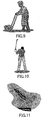
- FIG. 7 shows a flow of operations made in creating a movement of the legged locomotion robot 100 for a stable walking.
- the joint position and movement of the legged locomotion robot 100 will be described using a linear, noninterference multi-mass point approximate model as shown in FIGS. 5 and 6.
- a foot movement is set (in step S1).
- the foot movement is motion data on a time-series connection of two or more robot pauses.
- the motion data include, for example, joint space information representing an angle change of each joint of the feet, and Cartesian space information representing a joint position.
- the motion data can be formed by screen-touch input on a console display screen or by a direct teaching to the robot, for example, a motion edition authoring system.
- a ZMP stable region is calculated based on the set foot movement (in step S2).
- ZMP is a point where a moment applied to the robot is zero, and it basically exists on or insides the sides of a supporting polygon defined by points the foot sole touches and walking surface.
- the ZMP stable region is a zone set in a position more deeply inside the sizes of the supporting polygon, and it can set the robot in a highly stable state by placing the ZMP in the region.
- a ZMP trajectory for the foot movement is set on the basis of the foot movement and ZMP stable region (in step S3).
- ZMP trajectories are set for a group of points of the upper half of the robot (above the hip joint), such as hip, trunk, upper limbs, head, etc. (in step S 11).
- a desired trajectory is set for each of the component group (in step S12).
- the trajectory setting for the upper half of the robot can be done by screen-touch input on a console display screen or by a direct teaching to the robot, for example, a motion edition authoring system, similarly to the trajectory setting for the feet.
- step S13 an adjustment (re-grouping) is made of the trajectory setting for each point (in step S13), and an order of priority is given to the re-grouped points (in step S14) for trajectory setting.
- the "order of priority" referred to herein is an order in which the points of the robot are processed for the robot control for a stable posture.
- the priority is allocated in a comparative order in amount of the mass movement in the points.
- priority-assigned groups of desired trajectories are made of the points on the upper half of the robot.
- the priority order may be changed between target trajectories correspondingly to a robot posture.
- a mass usable for the moment compensation is calculated for each group of points of the upper half of the robot (in step S 15).
- a movement pattern for each group of the robot points is put into the posture stabilizing operation in the priority order set in step S14 on the base of the foot movement, ZMP trajectory and a group of desired trajectories for each group of points on the upper half of the robot.
- an initial value 1 is put in the place of a processing variable "i" (in step S20).
- a moment amount on the target ZMP that is, a total moment compensation amount, to be used for setting target trajectories for groups of points whose priority orders range from the top to i-th (in step S21).
- a desired trajectory is used for a point for which no target trajectory has been calculated.
- a moment compensation amount is set for the point (in step S22) and calculated (in step S23).
- a ZMP equation is derived for the i-th point (in step S24) and a moment compensation amount is calculated for that point (in step S25), to thereby permit to provide target trajectories for the points whose priority orders range from the top to i-th.
- a whole-body movement pattern for a stable movement (walking, for example) can be generated. That is, the whole-body movement pattern is generated by correcting all or a part of the target trajectories according to the solution of the ZMP equation (or dynamic equation which will be described in detail later) and a priority order assigned to each point.
- a foot movement is set to calculate a stable region for setting a ZMP trajectory, and then there are set priority orders of desired trajectories for the points on the upper half of the robot.
- the robot movement pattern may be generated in any other way.
- priority orders of desired trajectories for the points on the upper half of the robot may first be set, and then the ZMP stable region calculation and ZMP trajectory setting may be done.
- the priority orders of the desired trajectories are for the points on the upper half of the robot according to a ZMP trajectory having been set in advance.
- the stable region is calculated and ZMP trajectory is set to maintain the desired trajectory for each point on the upper half of the robot, having been set in advance.
- FIG. 8 shows a flow of operations made in generation of a robot movement by calculating a ZMP stable region and setting a ZMP trajectory after first setting a priority order for each of the points on the upper half of the robot.
- ZMP trajectories are set for a group of points of the upper half of the robot (above the hip joint), such as hip, trunk, upper limbs, head, etc. (in step S31).
- a desired trajectory is set for each of the component group (in step S32).
- the trajectory setting for the upper half of the robot can be done by screen-touch input on a console display screen or by a direct teaching to the robot, for example, a motion edition authoring system, similarly to the trajectory setting for the feet.
- step S33 an adjustment (re-grouping) is made of the trajectory setting for each point (in step S33), and an order of priority is given to the re-grouped points (in step S34) for trajectory setting.
- the "order of priority" referred to herein is an order in which the points of the robot are processed for the robot control for a stable posture.
- the priority is allocated in a comparative order in amount of the mass movement in the points.
- priority-assigned groups of desired trajectories are made of the points on the upper half of the robot.
- the priority order may be changed between target trajectories correspondingly to a robot posture.
- a ZMP stable region is calculated on the basis of the priority orders assigned to the desired trajectories set for the points on the upper half of the robot (in step S35). Then, a ZMP trajectory of a foot movement is set on the basis of the ZMP stable region (in step S36).
- a mass usable for the moment compensation is calculated for each group of points of the upper half of the robot (in step S45).
- a movement pattern for each group of the robot points is put into the posture stabilizing operation in the priority order set in step S34 on the base of the group of desired trajectories for each group of points on the upper half of the robot and ZMP trajectory.
- an initial value 1 is put in the place of a processing variable "i" (in step S37).
- a moment amount on the target ZMP that is, a total moment compensation amount, to be used for setting target trajectories for groups of points whose priority orders range from the top to i-th (in step S38).
- a desired trajectory is used for a point for which no target trajectory has been calculated.
- a moment compensation amount is set for the point (in step S39) and calculated (in step S40).
- a ZMP equation is derived for the i-th point (in step S41) and a moment compensation amount is calculated for that point (in step S42), to thereby permit to provide target trajectories for the points whose priority orders range from the top to i-th.
- the moment compensation amount for the area "i” will be ⁇ i ⁇ ⁇ [Nm] where "i" is an absolute moment compensation amount coefficient and represented as follows using a relative moment compensation coefficient ⁇ i:
- the positive-going direction of the priority order contributes to a stabler movement while the negative-going direction results in a lower stability.
- the priority of the hand trajectory is set higher.
- the priority is set in the order of the hands and feet.
- the priority is set for the hands, trunk, hip and feet in an descending order.
- the whole body is supported on both hands to stabilize the posture.
- the priority is set for the hands, trunk and hip in a descending order.
- a higher priority is set for the start of moving the player's head.
- the priority is set higher for the trunk.
- the priority for the lower limbs, hip, trunk and upper limbs is variable as the time elapses.
- the priority of the upper limbs ⁇ 0.0 in the last period.
- the priorities of the trajectories of all points are set uniformly high.
- the priority is set for the feet, upper limbs and trunk in a descending order.
- the priority is set for the upper limbs, trunk and feet in a descending order.
- the conventional legged locomotion robot and designing of the robot on the basis of the dynamics are based on the assumption that the deformation of the robot when applied with an external force and torque is very small and can be neglected for movement of the entire robot. That is to say, since the conventional robot and its designing are based on the assumption that the distance between joints of the robot will not vary, one state sensor is sufficient for each element of the robot system.
- the robot when it is intended to provide a robot capable of making motions such as running and acceleration in a continuous and positive manner and thus having a high dynamic level, the robot will need a shock damping function utilizing even the deformation of the mechanical hardware itself and have a function to real-time solve a higher-order equation rapidly.
- the legged locomotion robot uses a ZMP (zero-moment point) as a stability criterion.
- the ZMP-based stability criterion is such that a system forms an appropriate ZMP space and when a ZMP exists inside a supporting polygon, no rotation and translation will occur in the system and thus no dynamic equation of any rotation and translation has not to be solved. It should be noted however that in case no ZMP exists inside the supporting polygon or in case no supporting point of action for the surrounding exists, a dynamic equation has to be solved in place of a ZMP equation.
- the ZMP equation for the robot is a description of the balanced relation between the moments applied at the controlled-object point.
- the robot is represented by multiple mass points m i , and in case the mass points are taken as the controlled -object points, the ZMP equation is used to determine the sum of the moments applied at all the controlled-object points m i .
- the above ZMP equations state that the sum of moments about the ZMP (radius r i - r zmp ), developed due to an acceleration component applied at each mass point (or control point) m i , the sum of external force moment M i applied to each of the mass points m i , and the sum of moments about the ZMP (the point of action of k-th external force F k is taken s k ), developed due to the external force F k , are balanced with each other.
- the equation of ZMP equilibrium includes a total moment compensation amount, namely, a moment error component T.
- the robot is kept in a stable posture by suppressing the moment error to zero or within a predetermined allowable range.
- correction of the robot movement (trajectories of the foot movement and upper-body components) for the moment error to be zero or less than an acceptable value is the key in the posture stability control using ZMP as a stability criterion.
- a reaction force sensor system to directly measure a ZMP and force is disposed at a point of direct contact with the surrounding, a local coordinate used for the movement control and an acceleration sensor and angular velocity sensor to directly measure the local coordinate are disposed, and an acceleration sensor and attitude sensor are provided at each vector position used in the calculation model, to thereby permit to directly measure control parameters required to introduce a ZMP equation (or a dynamic equation).
- a strict movement control can be implemented with an improved response, not on the assumption that the robot is rigid enough not to be deformable with any external force applied.
- reaction force sensor system is disposed as will be described below by way of example:
- the "point where the mass is concentrated” referred to herein means the center of gravity of the battery, that of the control unit, that of the link, that of the actuator, joint axis and other where the mass is concentrated.
- FIG. 20 shows an acceleration sensor, angular acceleration sensor and angular velocity sensor mounted at a point on the legged locomotion robot where the mass is concentrated. As shown, an external force sensor and external force moment sensor are mounted on the hand palm and foot sole as major points of contacts with the surrounding.
- an acceleration component applied at each control point is directly measured at each control point, and thus there can be directly calculated at each point a moment term about a ZMP, thus generated, an external force moment term applied to the control point, a movement term about a ZMP, developed due to an external force applied to the control point.
- the moment terms collected from the control points are sequentially summed in the main control unit, to thereby permit to directly introduce a stricter ZMP equation of equilibrium.
- a moment term is directly measured at each control point, a strict movement control can be implemented with an improved response, not on the assumption that the robot is rigid enough not to be deformed by any external force applied.
- FIG. 21 shows an acceleration sensor, angular acceleration sensor and angular velocity sensor mounted at a point near the center of gravity of each link on the legged locomotion robot. As shown, an external force sensor and external force moment sensor are mounted on the hand palm and foot sole as major points of contacts with the surrounding.
- FIG. 22 shows an acceleration sensor, angular acceleration sensor and angular velocity sensor mounted at a point near the center of gravity of each actuator on the legged locomotion robot. As shown, an external force sensor and external force moment sensor are mounted on the hand palm and foot sole as major points of contacts with the surrounding.
- the distributed type reaction force sensor system as illustratively described in (1) to (5) above can measure an actual center of rotation on the basis of the information from the acceleration sensor located at each control point. Therefore, different from the conventional case in which the center of gravity can uniquely be determined from the design information on the robot, it is possible to dynamically calculate a more accurate position of the center of gravity even if the link of the robot is deformed by any external force.
- FIG. 23 shows a flow of operations made in the movement control of the legged locomotion robot according to this embodiment.
- the legged locomotion robot is determined to check the posture stability (in step S51). It can be judged referring to the supporting polygon on the robot whether the ZMP position is within the stable region.
- step S52 a ZMP equation will be solved using an appropriate ZMP space formed by the system, thereby controlling the robot to take a stable posture (will be described in detail later).
- a dynamic equation is solved in place of a ZMP equation (in step S53) to control the posture stability.
- FIG. 24 shows a flow of operations made in controlling the robot stability on the basis of a solution of a ZMP equation as in step S52.
- a ZMP is measured or the center of gravity is measured on the basis of information from the acceleration sensor, angular acceleration sensor and angular velocity sensor provided at each control point such as a point where the mass is concentrated, a point near the center of gravity of each link and a point near the center of gravity of each actuator (in step S61).
- the robot is deformed under the action of an external force applied, it is necessary to dynamically measure the center of gravity on the basis of a measurement made by the acceleration sensor.
- a moment term about a ZMP at each control point an external force moment term applied to the control point and a moment about a ZMP, developed due to an external force applied to the control point are calculated directly based on information from a sensor provided at each control point.
- the calculation is first made of moments at a point near ZMP or center of gravity. These moment terms are added one after another to determine a sum of them.
- a moment error T can be calculated using a ZMP equation (in step S70).
- step S71 With an external force moment identified as the state of each measured point being taken as an initial value, the ZMP trajectory or rotating trajectory of the center of gravity and the trajectory of each point are re-planned (in step S71).
- this processing routine is ended with sending a target value based on the result of the re-planning to the actuator system group.
- the procedure shown in FIG. 24 includes an operation for calculation of a moment developed at the series of i-th control points, operation for calculation of an external force moment applied at the series of j-th control points, and operation for calculation of a moment about a ZMP, developed due to an external force at the series of k-th control points and the operations for the i-th, j-th and k-th point series are made serially, these operations may be effected in parallel (as will be described in detail later).
- FIG. 25 shows a flow of operations made in controlling the robot stability on the basis of a solution of a dynamic equation in step S53.
- a floor reaction force F r at a ZMP is measured (in step S81).
- a translational force applied at each control point a translational force applied due to a moment about a ZMP and an external force are calculated directly based on information from a sensor provided at each control point.
- the calculation is first made of moments at a point near ZMP or center of gravity. These translational force terms are added one after another to determine a sum of them.
- an unknown external force F can be calculated under the d'Alembert's principle (in step S90).
- step S91 With the unknown external force F identified as an amount of information at each measured point being taken as an initial value, the ZMP trajectory or trajectory of the center of gravity and trajectory of each point are re-planned (in step S91).
- this processing routine is ended with sending a target value based on the result of the re-planning to the actuator system group.
- the procedure shown in FIG. 25 includes an operation for calculation of a translational force developed at the i-th control point, operation for calculation of a translational force developed due to an external force moment at the j-th control point, and operation for calculation of an external force applied at the k-th control point and the operations for the i-th, j-th and k-th points are made serially, these operations may be effected in parallel (as will be described in detail later).
- a moment term about a ZMP at each control point, an external force moment term applied to the control point and a moment about a ZMP, developed due to an external force applied to the control point are calculated directly based on information from a sensor provided at the control point.
- the calculation is first made of moments at a point near ZMP or center of gravity. These moment terms are added one after another to determine a sum of them, thereby permitting to introduce a ZMP equation.
- a translational force applied to each control point a translational force applied due to a moment about a ZMP and an external force are calculated directly based on information from a sensor provided at each control point.
- the calculation is first made of moments at a point near ZMP or center of gravity. These moment terms are added one after another to determine a sum of them, thereby permitting to introduce a dynamic equation for the translation and rotation.
- the legged locomotion robot includes the local coordinate used for the posture control and the acceleration sensor and angular velocity sensor disposed at each control point to directly measure the local coordinate, and the acceleration sensor and attitude sensor disposed at each vector position used in the calculation model. That is, the robot is constructed to directly measure control parameter values required to introduce a ZMP equation (or a dynamic equation).
- FIG. 22 shows the acceleration sensor, angular acceleration sensor and angular velocity sensor mounted near the center of gravity of each actuator on the legged locomotion robot as having previously been described.
- FIG. 26 shows an example in which the sensors are connected in series to each other.
- the sensors provided at the right and left upper limbs and right and left lower limbs are independent of each other and connected in series to each other so that the main control unit will be both the start and end points of the sensors.
- the results of calculation made based on the sensor information on the control point are added one after another, and the data is returned to the main control unit where they will be summed. In this calculation, the equation can be introduced.
- FIG. 27 shows another example in which the sensors are connected in series to each other.
- the sensors disposed over the robot are connected in line so that the central control unit will be both the start and end points of the sensors. Because of this wiring, the results of calculation made based on the sensor information from each control point are added one after another for each control point. The sum of each term is already determined when the data is returned to the central control unit. Thus, the main control unit can easily introduce the equations.
- the local coordinate used for the purpose of control, and acceleration sensor and angular velocity sensor to directly measure the local coordinate are provided at each control point, and in addition, the acceleration sensor and attitude sensor are disposed in each vector position used in the calculation model. This has been already illustrated and described using an example in which an acceleration, angular acceleration and angular velocity sensors are mounted near the center of gravity of each actuator where the mass is concentrated.
- FIG. 28 shows an example construction of a joint actuator having acceleration, angular acceleration and angular velocity sensors mounted near the center of the actuator unit.
- the joint actuator shown in FIG. 28 includes a motor formed from a rotor magnet and a stator formed from a magnetic coil having a plurality of phases, a gear unit (GU) to accelerate and decelerate the rotation output of the motor, and a control unit to control the power supply to the motor.
- a motor formed from a rotor magnet and a stator formed from a magnetic coil having a plurality of phases
- a gear unit to accelerate and decelerate the rotation output of the motor
- a control unit to control the power supply to the motor.
- the control unit is formed from a printed wiring board, for example, and has a sensor unit mounted nearly in the center thereof.
- the sensor unit is disposed near the two-dimensional center of gravity of the actuator unit.
- the sensor unit includes a combination of one- to three-axis acceleration sensors, one- and two-axis angular velocity sensors and a three-axis angular velocity sensor.
- FIG. 29 schematically illustrates the functional construction of the joint actuator.
- the actuator indicated with a reference 10 includes an interface 11, command processor 12, motor controller 13 and a sensor signal processor 14.
- the interface 11 implements an interface protocol in relation to a host controller.
- the command processor 12 processes a host command received via the interface 11 and sends it to the motor controller 13 or calculates sensor information from the sensor information processor 14 and returns it to the host controller via the interface 11.
- the motor controller 13 supplies, by PWM (pulse width modulation), the motor coil 15 with a current signal to implement a motor revolution complying with a host command, and acquires angular information from a sensor 16 which detects the rotational position of the rotor (not shown).
- PWM pulse width modulation
- the sensor signal processor 14 processes sensor information from the acceleration sensors (X to Y) and gyro sensors (pitch, roll and yaw) included in the sensor unit.
- a moment term about a ZMP at each control point, external force moment term applied to the control point and a moment term about a ZMP, developed to an external forced applied to the control point can be directly calculated based on sensor information for the sensors provided at each control point. This calculation is first done of such data from the sensors provided near the ZMP or center of gravity.
- a translational force applied to each control point, translational force applied due to a moment about a ZMP, and an external force can be directly calculated based on information from the sensors provided at each control point. This calculation is first made of such data from the sensors provided near the ZMP or center of gravity.
- a moment term and external force term calculated based on the sensor information from the sensor at each control point are added one after another for each control point along the connection route.
- the command processor 12 can add the moment term and external force term one after another for each control point along the connection route with the use of the sensor information supplied from the acceleration sensors (X to Y), gyro sensors (pitch, roll and yaw) and having been processed by the sensor signal processor 14.
- FIG. 30 shows a sequential addition, done in the joint actuator at each control point, of a moment term about a ZMP, external force moment term applied to the control point, and a moment term about the ZMP, developed due to an external force applied to the control point.
- the joint actuator is supplied, from a higher-order joint actuator in the connection route, with a sum of moment terms about a ZMP at the control points down to the (i-1)th control point, a sum of external force moment terms at the control points down to the (j-1)th control point, and a sum of moment terms about a ZMP, developed due to an external force, at the control points down to the (k-1)th control point.
- the moment term about ZMP at the control point, external force moment applied to the control point and moment term about a ZMP, developed due to an external force applied to the control point are calculated based on sensor information detected in the joint actuator, and they are added to the sum of each of such terms.
- the results are supplied to a lower-order joint actuator in the connection route as a sum of the moment terms about a ZMP at the control points down to the i-th control point, sum of the external force moments at the control points down to the j-th control point and sum of the moments about a ZMP, developed due to external forces applied to the control points down to the k-th control point. Therefore, by adding the data repeatedly along the connection route, moment terms forming a ZMP equation have already been determined when the result of calculation arrives at the main control unit. So, it is possible to implement the robot posture control using the ZMP-based stability criterion.
- the introduction of an equation of ZMP equilibrium involves a calculation of a moment developed at the series of i-th control points, calculation of an external force moment applied to the series of j-th control points and a calculation of a moment about a ZMP, developed due to an external force, at the series of k-th control points.
- the calculations of the data from the i-th, j-th and k-th control point series are done in parallel.
- a system in which data from the i-th, j-th and k-th control point series are calculated in parallel is advantageous in a reduced wiring.
- all the i-th, j-th and k-th control point series are not necessary but a system in which the calculation may be limited to that of data from the i-th control point series or may be skipped over that of the data from the i-th control points to the calculation of data from the (i-1)th control point series.
- FIG. 31 shows a sequential addition, in the joint actuator at each control point, of a translation force term applied to the control point, translation force terminal applied due to a moment about a ZMP, and an external force term.
- the joint actuator is supplied, from a higher-order joint actuator in the connection route, with a sum of translational force terms applied to the control points down to the (i-1)th control point, a sum of translational force terms applied due to a moment about a ZMP at the control points down to the (j-1)th control point, and a sum of external force terms applied to the control points down to the (k-1)th control point.
- the translational force applied to the control point, translational force applied due to the moment about a ZMP and external force term are calculated based on sensor information detected in the joint actuator, and they are added to the sum of each of such terms.
- the results are supplied to a lower-order joint actuator in the connection route as a sum of the translational force applied to the control points down to the i-th control point, sum of the translation force terms applied due the moment about a ZMP at the control points down to the j-th control point and sum of the external force terms applied to the control points down to the k-th control point. Therefore, by adding the data repeatedly along the connection route, moment terms forming a dynamic equation have already been determined when the result of calculation arrives at the main control unit. So, it is possible to implement the robot posture control using the dynamic equation.
- the introduction of a dynamic equation involves a calculation of a translational force at the series of i-th control points, calculation of a translational force developed due to an external force moment at the series of j-th control points and a calculation of an external force applied to the series of k-th control points.
- the calculations of the data from the i-th, j-th and k-th control point series are done in parallel.
- a system in which data from the i-th, j-th and k-th control point series are calculated in parallel is advantageous in a reduced wiring.
- all the i-th, j-th and k-th control points are not necessary but a system in which the calculation may be limited to that of data from the i-th control point series or may be skipped over that of the data from the i-th control point series to the calculation of data from the (i-1)th control point series.
- the present invention is not always limited to a product called “robot” but is applicable to a mechanical device designed to mimic the human motions with the use of the electrical or magnetic actions or any other general mobile devices such as toys belonging to other fields of industry.
- the present invention can provide an improved and novel movement controlling device and method for a legged locomotion robot, capable of making, based on a ZMP as a posture-stability criterion, a control for stabilization of the robot posture in moving.
- the present invention can provide an excellent movement controlling device and method for a legged locomotion robot, capable of strictly controlling the robot to take a stable posture by deriving a ZMP equation quickly and with a high accuracy.
- the present invention can provide an excellent movement controlling device and method and an improved and novel sensor system for the legged locomotion robot, capable of well controlling, based on a ZMP as a posture-stability criterion, the robot to take a stable posture.
- the present invention can provide an excellent movement controlling device and method, and an excellent sensor system for the legged locomotion robot, capable of well controlling the robot movement by identifying an unknown external force moment and unknown external force using a ZMP equation introduced based on measured values from sensors provided at various points on the robot.
- a reaction force sensor system to directly measure a ZMP and force is disposed at a point of direct contact with the surrounding, a local coordinate used for the movement control and an acceleration sensor and angular velocity sensor to directly measure the local coordinate are disposed, and an acceleration sensor and attitude sensor are provided at each vector position used in the calculation model, to thereby permit to directly measure control parameters required to introduce a ZMP equation (or a dynamic equation).
- a strict movement control can be implemented with an improved response, not on the assumption that the robot is rigid enough not to be deformable with any external force applied.
Landscapes
- Engineering & Computer Science (AREA)
- Mechanical Engineering (AREA)
- Chemical & Material Sciences (AREA)
- Combustion & Propulsion (AREA)
- Transportation (AREA)
- Human Computer Interaction (AREA)
- Robotics (AREA)
- Manipulator (AREA)
Priority Applications (2)
| Application Number | Priority Date | Filing Date | Title |
|---|---|---|---|
| EP10187802.3A EP2305436B1 (fr) | 2002-03-18 | 2003-03-18 | Dispositif de robot, contrôle des mouvements de robot |
| EP10187792.6A EP2298506B1 (fr) | 2002-03-18 | 2003-03-18 | Appareil locomoteur et contrôleur de cet appareil locomoteur |
Applications Claiming Priority (5)
| Application Number | Priority Date | Filing Date | Title |
|---|---|---|---|
| JP2002073498 | 2002-03-18 | ||
| JP2002073498 | 2002-03-18 | ||
| JP2002297207 | 2002-10-10 | ||
| JP2002297207 | 2002-10-10 | ||
| PCT/JP2003/003228 WO2003078110A1 (fr) | 2002-03-18 | 2003-03-18 | Robot, controleur de robot a jambes et procede correspondant, systeme de capteurs pour robot a jambes, et appareil locomoteur |
Related Child Applications (3)
| Application Number | Title | Priority Date | Filing Date |
|---|---|---|---|
| EP10187802.3A Division EP2305436B1 (fr) | 2002-03-18 | 2003-03-18 | Dispositif de robot, contrôle des mouvements de robot |
| EP10187802.3 Division-Into | 2010-10-15 | ||
| EP10187792.6 Division-Into | 2010-10-15 |
Publications (3)
| Publication Number | Publication Date |
|---|---|
| EP1486298A1 true EP1486298A1 (fr) | 2004-12-15 |
| EP1486298A4 EP1486298A4 (fr) | 2008-10-22 |
| EP1486298B1 EP1486298B1 (fr) | 2011-05-04 |
Family
ID=28043744
Family Applications (3)
| Application Number | Title | Priority Date | Filing Date |
|---|---|---|---|
| EP10187792.6A Expired - Lifetime EP2298506B1 (fr) | 2002-03-18 | 2003-03-18 | Appareil locomoteur et contrôleur de cet appareil locomoteur |
| EP03710407A Expired - Lifetime EP1486298B1 (fr) | 2002-03-18 | 2003-03-18 | Robot avec controleur de robot |
| EP10187802.3A Expired - Lifetime EP2305436B1 (fr) | 2002-03-18 | 2003-03-18 | Dispositif de robot, contrôle des mouvements de robot |
Family Applications Before (1)
| Application Number | Title | Priority Date | Filing Date |
|---|---|---|---|
| EP10187792.6A Expired - Lifetime EP2298506B1 (fr) | 2002-03-18 | 2003-03-18 | Appareil locomoteur et contrôleur de cet appareil locomoteur |
Family Applications After (1)
| Application Number | Title | Priority Date | Filing Date |
|---|---|---|---|
| EP10187802.3A Expired - Lifetime EP2305436B1 (fr) | 2002-03-18 | 2003-03-18 | Dispositif de robot, contrôle des mouvements de robot |
Country Status (6)
| Country | Link |
|---|---|
| US (2) | US7881824B2 (fr) |
| EP (3) | EP2298506B1 (fr) |
| KR (2) | KR100959472B1 (fr) |
| CN (3) | CN1649698A (fr) |
| DE (1) | DE60336992D1 (fr) |
| WO (1) | WO2003078110A1 (fr) |
Cited By (5)
| Publication number | Priority date | Publication date | Assignee | Title |
|---|---|---|---|---|
| WO2007046568A1 (fr) * | 2005-10-19 | 2007-04-26 | Korea Institute Of Science And Technology | Procede permettant de commander la marche d'un robot humanoide |
| EP1795437A2 (fr) * | 2005-12-12 | 2007-06-13 | HONDA MOTOR CO., Ltd. | Robot mobile doté de jambes et dispositif et mèthod pour son commande. |
| WO2009124951A1 (fr) * | 2008-04-09 | 2009-10-15 | Aldebaran Robotics | Architecture de controle - commande d'un robot mobile utilisant des membres articules |
| EP2343230A1 (fr) * | 2010-01-12 | 2011-07-13 | Samsung Electronics Co., Ltd. | Robot et son procédé de commande |
| WO2013017676A1 (fr) * | 2011-08-04 | 2013-02-07 | Aldebaran Robotics | Robot a articulations de rigidite variable et methode de calcul de ladite rigidite optimisee |
Families Citing this family (103)
| Publication number | Priority date | Publication date | Assignee | Title |
|---|---|---|---|---|
| KR100835361B1 (ko) * | 2003-08-29 | 2008-06-04 | 삼성전자주식회사 | 간이 지면반력 센서를 이용한 보행 로봇 및 그 제어 방법 |
| US20050053909A1 (en) * | 2003-09-08 | 2005-03-10 | Chan Kwok Hung | Learn-and-play programming method for motorized toys and domestic appliances |
| US7603199B2 (en) * | 2003-11-27 | 2009-10-13 | Honda Motor Co., Ltd. | Control device for mobile body |
| KR100543709B1 (ko) * | 2003-12-23 | 2006-01-20 | 삼성전자주식회사 | 이동체의 회전 이동량 이용 방법과 장치 및 컴퓨터프로그램을 저장하는 컴퓨터로 읽을 수 있는 기록 매체 |
| JP4971977B2 (ja) * | 2004-03-31 | 2012-07-11 | 本田技研工業株式会社 | 角運動量の変化率に基づいて脚式ロボットを制御する方法 |
| JP4305323B2 (ja) * | 2004-08-11 | 2009-07-29 | ソニー株式会社 | ロボット装置の動作制御装置及び動作制御方法 |
| US7835822B2 (en) * | 2005-03-30 | 2010-11-16 | Honda Motor Co., Ltd. | Systems and methods for controlling a legged robot using a two-phase disturbance response strategy |
| JP4456561B2 (ja) * | 2005-12-12 | 2010-04-28 | 本田技研工業株式会社 | 自律移動ロボット |
| JP4508164B2 (ja) * | 2006-06-26 | 2010-07-21 | トヨタ自動車株式会社 | 多関節ロボット及びその制御プログラム |
| JP4840239B2 (ja) * | 2007-04-20 | 2011-12-21 | トヨタ自動車株式会社 | 脚式移動ロボットの制御方法及び脚式移動ロボット |
| KR100912874B1 (ko) * | 2007-06-28 | 2009-08-19 | 삼성전자주식회사 | 이동 로봇의 리로케이션 방법 및 장치 |
| JP4440956B2 (ja) * | 2007-09-12 | 2010-03-24 | トヨタ自動車株式会社 | 脚式ロボット、及びその制御方法 |
| JP4392037B2 (ja) * | 2007-09-12 | 2009-12-24 | トヨタ自動車株式会社 | 脚式ロボット、及びその制御方法 |
| JP4985776B2 (ja) * | 2007-09-25 | 2012-07-25 | 富士通株式会社 | ロボット制御装置、ロボット制御方法およびロボット制御プログラム |
| US8138707B2 (en) * | 2007-10-23 | 2012-03-20 | Honda Motor Co., Ltd. | Bipedal walking robot |
| WO2009113359A1 (fr) * | 2008-03-12 | 2009-09-17 | 本田技研工業株式会社 | Système de travail et procédé d'automatisation du travail |
| KR101466312B1 (ko) * | 2008-06-11 | 2014-11-27 | 삼성전자 주식회사 | 보행 로봇 및 그 제어 방법 |
| CN101408435B (zh) * | 2008-10-31 | 2013-02-13 | 北京理工大学 | 仿人机器人着地时脚踝的运动规划方法和装置 |
| KR20110016521A (ko) * | 2009-08-12 | 2011-02-18 | 삼성전자주식회사 | 인간형 로봇의 전신 동작 제어 장치 및 그 방법 |
| KR101667032B1 (ko) * | 2009-10-30 | 2016-10-17 | 삼성전자 주식회사 | 로봇의 경로 계획 장치 및 그 방법 |
| KR101687628B1 (ko) * | 2010-01-12 | 2016-12-21 | 삼성전자주식회사 | 로봇의 보행 제어 장치 및 그 제어 방법 |
| WO2011106543A1 (fr) * | 2010-02-25 | 2011-09-01 | Honda Motor Co., Ltd. | Régulateur d'équilibre à base de moments pour robots humanoïdes sur sol inégal et non statique |
| CN101847009B (zh) * | 2010-05-28 | 2011-12-14 | 广东工业大学 | 两足机器人步态能效优化方法 |
| KR101200191B1 (ko) * | 2010-07-14 | 2012-11-13 | 서울대학교산학협력단 | 데이터 기반 바이페드 제어 장치 및 방법 |
| US8731714B2 (en) | 2010-09-22 | 2014-05-20 | GM Global Technology Operations LLC | Concurrent path planning with one or more humanoid robots |
| US8777818B1 (en) * | 2010-12-22 | 2014-07-15 | Larry E. Tate, Jr. | Training device |
| JP5991857B2 (ja) * | 2011-06-10 | 2016-09-14 | 三星電子株式会社Samsung Electronics Co.,Ltd. | ロボットの均衡制御装置及びその制御方法 |
| US9412010B2 (en) * | 2011-07-15 | 2016-08-09 | Panasonic Corporation | Posture estimation device, posture estimation method, and posture estimation program |
| KR101262978B1 (ko) * | 2011-12-05 | 2013-05-08 | 현대자동차주식회사 | 보행로봇의 반발력 측정 모듈 및 방법 |
| KR20130078886A (ko) * | 2012-01-02 | 2013-07-10 | 현대자동차주식회사 | 보행로봇의 균형제어방법 |
| US9573276B2 (en) * | 2012-02-15 | 2017-02-21 | Kenneth Dean Stephens, Jr. | Space exploration with human proxy robots |
| JP5896789B2 (ja) * | 2012-03-07 | 2016-03-30 | キヤノン株式会社 | ロボット制御装置、ロボット装置、ロボット制御方法、プログラム及び記録媒体 |
| US9156159B2 (en) * | 2012-03-08 | 2015-10-13 | Disney Enterprises Inc. | Robot cyclic locomotion using a dynamic object |
| CN102670217A (zh) * | 2012-05-04 | 2012-09-19 | 嘉兴市制衡精仪有限公司 | 下肢关节作用力和力矩的穿戴式传感器测量装置及方法 |
| CN102672719B (zh) * | 2012-05-10 | 2014-11-19 | 浙江大学 | 一种仿人机器人手臂作业动态稳定控制方法 |
| JP6332900B2 (ja) | 2012-08-31 | 2018-05-30 | セイコーエプソン株式会社 | ロボットシステム及びロボット制御装置 |
| CN103042526A (zh) * | 2013-01-22 | 2013-04-17 | 北京理工大学 | 仿人机器人控制单脚支撑期支撑脚板的方法和装置 |
| JP2014205197A (ja) * | 2013-04-10 | 2014-10-30 | セイコーエプソン株式会社 | ロボット、ロボット制御装置およびロボットシステム |
| JP6155780B2 (ja) | 2013-04-10 | 2017-07-05 | セイコーエプソン株式会社 | ロボット、ロボット制御装置およびロボットシステム |
| JP2014205199A (ja) | 2013-04-10 | 2014-10-30 | セイコーエプソン株式会社 | ロボット、ロボット制御装置およびロボットシステム |
| JP2014205198A (ja) | 2013-04-10 | 2014-10-30 | セイコーエプソン株式会社 | ロボット、ロボット制御装置およびロボットシステム |
| JP6354122B2 (ja) | 2013-06-05 | 2018-07-11 | セイコーエプソン株式会社 | ロボット |
| JP6330287B2 (ja) * | 2013-10-29 | 2018-05-30 | セイコーエプソン株式会社 | ロボット、ロボット用当接部材 |
| CN104608125B (zh) * | 2013-11-01 | 2019-12-17 | 精工爱普生株式会社 | 机器人、控制装置以及机器人系统 |
| JP2015136762A (ja) * | 2014-01-23 | 2015-07-30 | セイコーエプソン株式会社 | 処理装置、ロボット、ロボットシステム及び処理方法 |
| JP2015182143A (ja) * | 2014-03-20 | 2015-10-22 | セイコーエプソン株式会社 | ロボットおよびロボットシステム |
| KR101571313B1 (ko) * | 2014-06-20 | 2015-11-26 | 한국과학기술연구원 | 무게중심 제어를 통한 로봇의 자세 제어 시스템 |
| US9387588B1 (en) | 2014-08-25 | 2016-07-12 | Google Inc. | Handling gait disturbances with asynchronous timing |
| US10081098B1 (en) | 2014-08-25 | 2018-09-25 | Boston Dynamics, Inc. | Generalized coordinate surrogates for integrated estimation and control |
| US9517561B2 (en) * | 2014-08-25 | 2016-12-13 | Google Inc. | Natural pitch and roll |
| US9618937B1 (en) | 2014-08-25 | 2017-04-11 | Google Inc. | Slip detection using robotic limbs |
| US9623556B1 (en) | 2014-09-03 | 2017-04-18 | X Development Llc | Robotic sole joint |
| JP6356033B2 (ja) * | 2014-09-29 | 2018-07-11 | 本田技研工業株式会社 | 移動体の制御装置 |
| JP6339467B2 (ja) * | 2014-09-29 | 2018-06-06 | 本田技研工業株式会社 | 移動ロボットの制御装置 |
| JP5927270B2 (ja) * | 2014-11-06 | 2016-06-01 | ファナック株式会社 | ロボットシミュレーション装置 |
| US9446518B1 (en) * | 2014-11-11 | 2016-09-20 | Google Inc. | Leg collision avoidance in a robotic device |
| CN104434124A (zh) * | 2014-12-04 | 2015-03-25 | 电子科技大学 | 一种人体下肢步态数据采集系统 |
| US9592608B1 (en) * | 2014-12-15 | 2017-03-14 | X Development Llc | Methods and systems for providing feedback during teach mode |
| JP5927284B1 (ja) * | 2014-12-22 | 2016-06-01 | ファナック株式会社 | 人との接触力を検出してロボットを停止させるロボット制御装置 |
| US9440353B1 (en) | 2014-12-29 | 2016-09-13 | Google Inc. | Offline determination of robot behavior |
| US9499218B1 (en) | 2014-12-30 | 2016-11-22 | Google Inc. | Mechanically-timed footsteps for a robotic device |
| CN104765372B (zh) * | 2015-03-02 | 2017-11-10 | 湘潭大学 | 一种多足机器人保持直线平动的步态规划方法 |
| CN104843102A (zh) * | 2015-03-17 | 2015-08-19 | 北京理工大学 | 一种基于并联六自由度机构的减振足式机器人 |
| US9594377B1 (en) * | 2015-05-12 | 2017-03-14 | Google Inc. | Auto-height swing adjustment |
| CN105058398B (zh) * | 2015-08-04 | 2017-03-22 | 北京理工大学 | 一种球形轮移动机器人及其测速方法 |
| DE102015113486A1 (de) * | 2015-08-14 | 2017-02-16 | Northrop Grumman Litef Gmbh | Navigationsvorrichtung mit Drehtisch für eine Umschlagsmessung und Verfahren zum Betreiben der Navigationsvorrichtung |
| US9586316B1 (en) | 2015-09-15 | 2017-03-07 | Google Inc. | Determination of robotic step path |
| US9878751B1 (en) | 2015-10-08 | 2018-01-30 | Boston Dynamics, Inc. | Three-piston ankle mechanism of a legged robot and associated control system |
| CN105329333B (zh) * | 2015-11-20 | 2017-09-26 | 清华大学 | 基于延迟反馈的双足机器人行走非单周期步态控制方法 |
| CN105511465B (zh) * | 2015-12-02 | 2017-08-04 | 歌尔股份有限公司 | 一种双足机器人的步态控制方法和装置 |
| US9778132B1 (en) * | 2015-12-16 | 2017-10-03 | X Development Llc | Methods and systems for force sensor calibration |
| US9919422B1 (en) | 2016-01-06 | 2018-03-20 | X Development Llc | Methods and systems to provide mechanical feedback during movement of a robotic system |
| US9789919B1 (en) | 2016-03-22 | 2017-10-17 | Google Inc. | Mitigating sensor noise in legged robots |
| US9987745B1 (en) | 2016-04-01 | 2018-06-05 | Boston Dynamics, Inc. | Execution of robotic tasks |
| JP6660242B2 (ja) * | 2016-04-25 | 2020-03-11 | 本田技研工業株式会社 | ロボットの制御信号を伝送するための光ファイバ配線構造 |
| CN107346107A (zh) * | 2016-05-04 | 2017-11-14 | 深圳光启合众科技有限公司 | 多样化运动控制方法和系统及具有该系统的机器人 |
| JP6682341B2 (ja) * | 2016-05-10 | 2020-04-15 | パナソニック株式会社 | 歩行制御方法、歩行制御プログラム及び2足歩行ロボット |
| KR102503955B1 (ko) * | 2016-11-02 | 2023-02-28 | 삼성전자주식회사 | 밸런스 제어 방법 및 장치 |
| JP6977265B2 (ja) * | 2017-01-27 | 2021-12-08 | オムロン株式会社 | マスタースレーブ制御システム、およびマスタースレーブ制御システムの制御方法 |
| JP6927727B2 (ja) * | 2017-03-29 | 2021-09-01 | 本田技研工業株式会社 | ロボットの制御装置 |
| CN108972536B (zh) * | 2017-05-31 | 2021-06-22 | 西门子(中国)有限公司 | 机械臂的动力学参数确定系统、方法及存储介质 |
| JP2019093508A (ja) * | 2017-11-24 | 2019-06-20 | 川崎重工業株式会社 | 試験装置 |
| KR102418451B1 (ko) * | 2017-12-27 | 2022-07-07 | 주식회사 한화 | 로봇 제어 시스템 |
| CN109991989B (zh) * | 2017-12-29 | 2021-12-17 | 深圳市优必选科技有限公司 | 机器人空闲状态下的动态平衡方法、装置及存储介质 |
| CN108920228B (zh) * | 2018-05-28 | 2021-01-15 | 云谷(固安)科技有限公司 | 一种控制指令输入方法和输入装置 |
| US11577390B2 (en) * | 2018-06-05 | 2023-02-14 | Sony Corporation | Information processing device and information processing method |
| US11203122B2 (en) * | 2018-08-03 | 2021-12-21 | Digital Dream Labs, Llc | Goal-based robot animation |
| CN108744432B (zh) * | 2018-08-21 | 2024-04-19 | 常州市钱璟康复股份有限公司 | 一种跌倒评估与训练装置 |
| CN109048961B (zh) * | 2018-09-19 | 2021-10-01 | 哈尔滨工业大学 | 能摆荡抓握远距离桁架杆的攀爬桁架机器人及其控制方法 |
| WO2020107279A1 (fr) * | 2018-11-28 | 2020-06-04 | 深圳市优必选科技有限公司 | Robot bipède et procédé de déplacement associé, appareil et support d'informations |
| CN109857131A (zh) * | 2019-03-11 | 2019-06-07 | 山东职业学院 | 一种足式机器人两足-四足姿态变换控制方法 |
| JP7381709B2 (ja) * | 2019-08-06 | 2023-11-15 | ボストン ダイナミクス,インコーポレイテッド | 足跡接触検出 |
| CN110539310B (zh) * | 2019-08-06 | 2022-09-02 | 同济大学 | 一种高负载建筑机器人 |
| US11958183B2 (en) | 2019-09-19 | 2024-04-16 | The Research Foundation For The State University Of New York | Negotiation-based human-robot collaboration via augmented reality |
| CN110890148B (zh) * | 2019-12-19 | 2022-05-17 | 上海金矢机器人科技有限公司 | 一种基于康复训练器的安全防护系统及方法 |
| CN111037569B (zh) * | 2019-12-31 | 2021-06-22 | 达闼机器人有限公司 | 机器人平衡控制方法、装置、存储介质及机器人 |
| CN111872941B (zh) * | 2020-08-06 | 2021-09-07 | 深圳市优必选科技股份有限公司 | 平衡控制方法、装置、仿人机器人及可读存储介质 |
| CN112276959B (zh) * | 2020-12-25 | 2021-03-30 | 之江实验室 | 几何参数与关节零位自标定方法、装置、电子设备及介质 |
| CN112947312B (zh) * | 2021-01-28 | 2021-09-14 | 仲恺农业工程学院 | 一种农业机器人运动控制方法 |
| CN113552880B (zh) * | 2021-07-14 | 2023-08-04 | 中国北方车辆研究所 | 一种双足轮式机器人平衡控制方法 |
| CN114661057B (zh) * | 2022-05-23 | 2022-08-26 | 武汉跨克信息技术有限公司 | 一种智能仿生双足巡检机器人 |
| GB2620639A (en) * | 2022-07-15 | 2024-01-17 | Dyson Technology Ltd | Dynamic stability of a robot manipulator |
| US11738452B1 (en) * | 2022-07-29 | 2023-08-29 | Sarcos Corp. | Sole with various compliant regions for robots |
Citations (3)
| Publication number | Priority date | Publication date | Assignee | Title |
|---|---|---|---|---|
| EP1103451A2 (fr) * | 1999-11-25 | 2001-05-30 | Sony Corporation | Robot mobile muni de jambes - méthode et dispositif de contrôle de ce robot |
| EP1344611A1 (fr) * | 2000-11-20 | 2003-09-17 | Sony Corporation | Dispositif et procede permettant de commander le fonctionnement d'un robot a jambes et ensemble robot |
| EP1344612A1 (fr) * | 2000-11-17 | 2003-09-17 | Sony Corporation | Dispositif et procede de commande des mouvements d'un robot marcheur mobile et procede de generation d'unites de mouvement destinees a un robot marcheur mobile |
Family Cites Families (32)
| Publication number | Priority date | Publication date | Assignee | Title |
|---|---|---|---|---|
| JP2507891B2 (ja) * | 1989-02-01 | 1996-06-19 | 工業技術院長 | マニピュレ―タのインピ―ダンス制御方式 |
| US5101472A (en) * | 1990-10-04 | 1992-03-31 | Repperger Daniel W | Military robotic controller with majorizing function and nonlinear torque capability |
| US5355064A (en) * | 1992-03-04 | 1994-10-11 | Honda Giken Kogyo Kabushiki Kaisha | Control system for legged mobile robot |
| JP3270766B2 (ja) | 1992-03-04 | 2002-04-02 | 本田技研工業株式会社 | 脚式移動ロボットの制御装置 |
| US5337235A (en) * | 1992-03-12 | 1994-08-09 | Honda Giken Kogyo Kabushiki Kaisha | Locomotion control system for legged mobiled robot |
| US5349277A (en) * | 1992-03-12 | 1994-09-20 | Honda Giken Kogyo Kabushiki Kaisha | Control system for legged mobile robot |
| JP3167406B2 (ja) | 1992-03-12 | 2001-05-21 | 本田技研工業株式会社 | 脚式移動ロボットの歩行制御装置 |
| JPH05305581A (ja) | 1992-04-28 | 1993-11-19 | Honda Motor Co Ltd | リンク式移動ロボットの制御装置 |
| JP3148830B2 (ja) | 1992-04-30 | 2001-03-26 | 本田技研工業株式会社 | 脚式移動ロボットの歩行制御装置 |
| JP3167420B2 (ja) | 1992-04-30 | 2001-05-21 | 本田技研工業株式会社 | 脚式移動ロボットの歩行制御装置 |
| JP3148829B2 (ja) | 1992-04-30 | 2001-03-26 | 本田技研工業株式会社 | 脚式移動ロボットの歩行制御装置 |
| JP3148828B2 (ja) | 1992-04-30 | 2001-03-26 | 本田技研工業株式会社 | 脚式移動ロボットの歩行制御装置 |
| JP3273443B2 (ja) * | 1992-05-22 | 2002-04-08 | 本田技研工業株式会社 | ロボットのリンクなどの軌道生成方法及び装置 |
| US5445235A (en) * | 1992-05-26 | 1995-08-29 | Honda Giken Kogyo Kabushiki Kaisha | Legged mobile robot equipped with impact absorber |
| JP3269852B2 (ja) * | 1992-05-29 | 2002-04-02 | 本田技研工業株式会社 | 脚式移動ロボットの姿勢安定化制御装置 |
| JP2908194B2 (ja) | 1993-10-06 | 1999-06-21 | 日本電気株式会社 | 文字の変形制御方式 |
| US5808433A (en) * | 1995-09-29 | 1998-09-15 | Honda Giken Kogyo Kabushiki Kaisha | Method of generating gait of legged walking robot and system for controlling its locomotion |
| JP3662996B2 (ja) * | 1996-01-25 | 2005-06-22 | 本田技研工業株式会社 | 脚式移動ロボットの歩行制御装置 |
| US5872893A (en) * | 1996-07-25 | 1999-02-16 | Honda Giken Kogyo Kabushiki Kaisha | Gait generation system of legged mobile robot |
| JPH10128688A (ja) | 1996-09-04 | 1998-05-19 | Sankyo Seiki Mfg Co Ltd | ロボットの非干渉化制御方法 |
| US6243623B1 (en) * | 1997-01-31 | 2001-06-05 | Honda Giken Kogyo Kabushiki Kaisha | Leg type mobile robot control apparatus |
| JP3655056B2 (ja) | 1997-08-04 | 2005-06-02 | 本田技研工業株式会社 | 脚式移動ロボットの制御装置 |
| DE69943148D1 (de) * | 1998-04-20 | 2011-03-03 | Honda Motor Co Ltd | Steuereinheit für einen mit beinen beweglichen roboter |
| CN1146492C (zh) * | 1998-06-09 | 2004-04-21 | 索尼公司 | 机器人装置及其姿态控制方法 |
| US6216083B1 (en) * | 1998-10-22 | 2001-04-10 | Yamaha Motor Co., Ltd. | System for intelligent control of an engine based on soft computing |
| EP1155787B1 (fr) * | 1998-11-30 | 2016-10-05 | Sony Corporation | Robot et son procede de commande |
| JP3332226B2 (ja) | 1999-02-10 | 2002-10-07 | ソニー株式会社 | アクチュエータ装置 |
| JP3443077B2 (ja) * | 1999-09-20 | 2003-09-02 | ソニー株式会社 | ロボットの運動パターン生成装置及び運動パターン生成方法、並びにロボット |
| US6377013B2 (en) * | 1999-12-24 | 2002-04-23 | Honda Giken Kogyo Kabushiki Kaisha | Control apparatus for legged mobile robot |
| AU2001272980A1 (en) * | 2000-06-23 | 2002-01-08 | Sportvision, Inc. | Gps based tracking system |
| JP4733317B2 (ja) * | 2001-08-28 | 2011-07-27 | 本田技研工業株式会社 | 脚式歩行ロボットの床反力検出器 |
| US10410936B2 (en) * | 2017-05-19 | 2019-09-10 | Illinois Tool Works Inc. | Methods and apparatuses for effluent monitoring for brush conditioning |
-
2003
- 2003-03-18 CN CNA038096676A patent/CN1649698A/zh active Pending
- 2003-03-18 EP EP10187792.6A patent/EP2298506B1/fr not_active Expired - Lifetime
- 2003-03-18 CN CN200910262181.4A patent/CN101745910B/zh not_active Expired - Lifetime
- 2003-03-18 EP EP03710407A patent/EP1486298B1/fr not_active Expired - Lifetime
- 2003-03-18 DE DE60336992T patent/DE60336992D1/de not_active Expired - Lifetime
- 2003-03-18 KR KR1020107001919A patent/KR100959472B1/ko active IP Right Grant
- 2003-03-18 WO PCT/JP2003/003228 patent/WO2003078110A1/fr active Application Filing
- 2003-03-18 EP EP10187802.3A patent/EP2305436B1/fr not_active Expired - Lifetime
- 2003-03-18 US US10/508,062 patent/US7881824B2/en active Active
- 2003-03-18 CN CN200910262182.9A patent/CN101763118B/zh not_active Expired - Lifetime
- 2003-03-18 KR KR1020047014643A patent/KR101004820B1/ko active IP Right Grant
-
2010
- 2010-09-16 US US12/883,615 patent/US8612052B2/en active Active
Patent Citations (3)
| Publication number | Priority date | Publication date | Assignee | Title |
|---|---|---|---|---|
| EP1103451A2 (fr) * | 1999-11-25 | 2001-05-30 | Sony Corporation | Robot mobile muni de jambes - méthode et dispositif de contrôle de ce robot |
| EP1344612A1 (fr) * | 2000-11-17 | 2003-09-17 | Sony Corporation | Dispositif et procede de commande des mouvements d'un robot marcheur mobile et procede de generation d'unites de mouvement destinees a un robot marcheur mobile |
| EP1344611A1 (fr) * | 2000-11-20 | 2003-09-17 | Sony Corporation | Dispositif et procede permettant de commander le fonctionnement d'un robot a jambes et ensemble robot |
Non-Patent Citations (1)
| Title |
|---|
| See also references of WO03078110A1 * |
Cited By (15)
| Publication number | Priority date | Publication date | Assignee | Title |
|---|---|---|---|---|
| US8738178B2 (en) | 2005-10-19 | 2014-05-27 | Korea Institute Of Science And Technology | Method for controlling the walk of humanoid robot |
| WO2007046568A1 (fr) * | 2005-10-19 | 2007-04-26 | Korea Institute Of Science And Technology | Procede permettant de commander la marche d'un robot humanoide |
| EP1795437A2 (fr) * | 2005-12-12 | 2007-06-13 | HONDA MOTOR CO., Ltd. | Robot mobile doté de jambes et dispositif et mèthod pour son commande. |
| EP1795437A3 (fr) * | 2005-12-12 | 2007-08-22 | HONDA MOTOR CO., Ltd. | Robot mobile doté de jambes et dispositif et mèthod pour son commande. |
| EP1847449A1 (fr) * | 2005-12-12 | 2007-10-24 | HONDA MOTOR CO., Ltd. | Programmateur de robot marcheur mobile, robot marcheur mobile et procédé de commande de robot marcheur mobile |
| KR100798086B1 (ko) * | 2005-12-12 | 2008-01-28 | 혼다 기켄 고교 가부시키가이샤 | 다리식 이동 로봇 제어장치 및 다리식 이동 로봇, 및,다리식 이동 로봇의 제어 방법 |
| US7330775B2 (en) | 2005-12-12 | 2008-02-12 | Honda Motor Co., Ltd. | Legged mobile robot controller, legged mobile robot and legged mobile robot control method |
| WO2009124951A1 (fr) * | 2008-04-09 | 2009-10-15 | Aldebaran Robotics | Architecture de controle - commande d'un robot mobile utilisant des membres articules |
| FR2929873A1 (fr) * | 2008-04-09 | 2009-10-16 | Aldebaran Robotics Soc Par Act | Architecture de controle-commande d'un robot mobile utilisant des membres articules |
| US9327400B2 (en) | 2008-04-09 | 2016-05-03 | Aldebaran Robotics | Control-command architecture for a mobile robot using articulated limbs |
| EP2343230A1 (fr) * | 2010-01-12 | 2011-07-13 | Samsung Electronics Co., Ltd. | Robot et son procédé de commande |
| WO2013017676A1 (fr) * | 2011-08-04 | 2013-02-07 | Aldebaran Robotics | Robot a articulations de rigidite variable et methode de calcul de ladite rigidite optimisee |
| FR2978844A1 (fr) * | 2011-08-04 | 2013-02-08 | Aldebaran Robotics | Robot a articulations de rigidite variable et methode de calcul de ladite rigidite optimisee |
| CN104011613A (zh) * | 2011-08-04 | 2014-08-27 | 奥尔德巴伦机器人公司 | 具有可变刚度的关节的机器人和用于计算所述优化的刚度的方法 |
| US9555543B2 (en) | 2011-08-04 | 2017-01-31 | Aldebaran Robotics | Robot with joints of variable rigidity and method for calculating said optimized rigidity |
Also Published As
| Publication number | Publication date |
|---|---|
| KR100959472B1 (ko) | 2010-05-25 |
| EP2305436B1 (fr) | 2015-10-28 |
| US7881824B2 (en) | 2011-02-01 |
| EP1486298B1 (fr) | 2011-05-04 |
| KR20040111417A (ko) | 2004-12-31 |
| US20050240307A1 (en) | 2005-10-27 |
| EP2305436A1 (fr) | 2011-04-06 |
| DE60336992D1 (de) | 2011-06-16 |
| CN101763118B (zh) | 2015-09-02 |
| WO2003078110A1 (fr) | 2003-09-25 |
| US20110077775A1 (en) | 2011-03-31 |
| KR101004820B1 (ko) | 2010-12-28 |
| CN1649698A (zh) | 2005-08-03 |
| CN101763118A (zh) | 2010-06-30 |
| EP1486298A4 (fr) | 2008-10-22 |
| EP2298506B1 (fr) | 2013-09-11 |
| EP2298506A1 (fr) | 2011-03-23 |
| KR20100018103A (ko) | 2010-02-16 |
| CN101745910B (zh) | 2014-11-05 |
| US8612052B2 (en) | 2013-12-17 |
| CN101745910A (zh) | 2010-06-23 |
Similar Documents
| Publication | Publication Date | Title |
|---|---|---|
| EP2298506B1 (fr) | Appareil locomoteur et contrôleur de cet appareil locomoteur | |
| EP1103451B1 (fr) | Robot mobile muni de jambes - méthode et dispositif de contrôle de ce robot | |
| KR100837988B1 (ko) | 각식 이동 로봇을 위한 동작 제어 장치 및 동작 제어방법, 및 로봇 장치 | |
| EP1486299B1 (fr) | Dispositif de commande operationnelle pour robot mobile du type a jambes, procede de commande operationnelle, et robot | |
| US20060106495A1 (en) | Control device of legged mobile robot | |
| KR20010050543A (ko) | 로봇의 이동 제어 장치 및 이동 제어 방법 | |
| JP2004223712A (ja) | 歩行式ロボット及びその位置移動方法 | |
| WO2004033160A1 (fr) | Dispositif de commande des operations d'un robot et procede de commande des operations | |
| JP3528171B2 (ja) | 移動ロボット装置及び移動ロボット装置の転倒制御方法 | |
| JPH07205069A (ja) | 脚式移動ロボットの歩行制御装置 | |
| JP3674779B2 (ja) | 脚式移動ロボットのための動作制御装置及び動作制御方法、並びにロボット装置 | |
| JP3522742B1 (ja) | ロボット装置、脚式移動ロボットの動作制御装置及び動作制御方法、脚式移動ロボットのためのセンサ・システム、並びに移動体装置 | |
| JP3568527B2 (ja) | 移動体装置 | |
| JP3674787B2 (ja) | ロボット装置の動作制御装置及び動作制御方法、並びにコンピュータ・プログラム | |
| KR101048716B1 (ko) | 2족 로봇 및 2족 로봇의 보행 제어방법 | |
| Chen et al. | Application of Compliant Control in Position-Based Humanoid Robot |
Legal Events
| Date | Code | Title | Description |
|---|---|---|---|
| PUAI | Public reference made under article 153(3) epc to a published international application that has entered the european phase |
Free format text: ORIGINAL CODE: 0009012 |
|
| 17P | Request for examination filed |
Effective date: 20040920 |
|
| AK | Designated contracting states |
Kind code of ref document: A1 Designated state(s): AT BE BG CH CY CZ DE DK EE ES FI FR GB GR HU IE IT LI LU MC NL PT RO SE SI SK TR |
|
| A4 | Supplementary search report drawn up and despatched |
Effective date: 20080924 |
|
| 17Q | First examination report despatched |
Effective date: 20081117 |
|
| GRAP | Despatch of communication of intention to grant a patent |
Free format text: ORIGINAL CODE: EPIDOSNIGR1 |
|
| RTI1 | Title (correction) |
Free format text: ROBOT DEVICE WITH AN CONTROL DEVICE. |
|
| GRAS | Grant fee paid |
Free format text: ORIGINAL CODE: EPIDOSNIGR3 |
|
| GRAA | (expected) grant |
Free format text: ORIGINAL CODE: 0009210 |
|
| AK | Designated contracting states |
Kind code of ref document: B1 Designated state(s): DE FR GB |
|
| REG | Reference to a national code |
Ref country code: GB Ref legal event code: FG4D |
|
| REF | Corresponds to: |
Ref document number: 60336992 Country of ref document: DE Date of ref document: 20110616 Kind code of ref document: P |
|
| REG | Reference to a national code |
Ref country code: DE Ref legal event code: R096 Ref document number: 60336992 Country of ref document: DE Effective date: 20110616 |
|
| PLBE | No opposition filed within time limit |
Free format text: ORIGINAL CODE: 0009261 |
|
| STAA | Information on the status of an ep patent application or granted ep patent |
Free format text: STATUS: NO OPPOSITION FILED WITHIN TIME LIMIT |
|
| 26N | No opposition filed |
Effective date: 20120207 |
|
| REG | Reference to a national code |
Ref country code: DE Ref legal event code: R097 Ref document number: 60336992 Country of ref document: DE Effective date: 20120207 |
|
| REG | Reference to a national code |
Ref country code: FR Ref legal event code: PLFP Year of fee payment: 14 |
|
| REG | Reference to a national code |
Ref country code: FR Ref legal event code: PLFP Year of fee payment: 15 |
|
| REG | Reference to a national code |
Ref country code: FR Ref legal event code: PLFP Year of fee payment: 16 |
|
| PGFP | Annual fee paid to national office [announced via postgrant information from national office to epo] |
Ref country code: GB Payment date: 20220225 Year of fee payment: 20 Ref country code: DE Payment date: 20220217 Year of fee payment: 20 |
|
| PGFP | Annual fee paid to national office [announced via postgrant information from national office to epo] |
Ref country code: FR Payment date: 20220221 Year of fee payment: 20 |
|
| REG | Reference to a national code |
Ref country code: DE Ref legal event code: R071 Ref document number: 60336992 Country of ref document: DE |
|
| REG | Reference to a national code |
Ref country code: GB Ref legal event code: PE20 Expiry date: 20230317 |
|
| PG25 | Lapsed in a contracting state [announced via postgrant information from national office to epo] |
Ref country code: GB Free format text: LAPSE BECAUSE OF EXPIRATION OF PROTECTION Effective date: 20230317 |