EP1486273A1 - Stranggiesskokille mit Verstellorganen für mehrere Kupferplatten, die den Giesshohlraum umschliessen - Google Patents
Stranggiesskokille mit Verstellorganen für mehrere Kupferplatten, die den Giesshohlraum umschliessen Download PDFInfo
- Publication number
- EP1486273A1 EP1486273A1 EP04011889A EP04011889A EP1486273A1 EP 1486273 A1 EP1486273 A1 EP 1486273A1 EP 04011889 A EP04011889 A EP 04011889A EP 04011889 A EP04011889 A EP 04011889A EP 1486273 A1 EP1486273 A1 EP 1486273A1
- Authority
- EP
- European Patent Office
- Prior art keywords
- continuous casting
- piston
- cylinder housing
- casting mold
- cylinder
- Prior art date
- Legal status (The legal status is an assumption and is not a legal conclusion. Google has not performed a legal analysis and makes no representation as to the accuracy of the status listed.)
- Granted
Links
Images


Classifications
-
- B—PERFORMING OPERATIONS; TRANSPORTING
- B22—CASTING; POWDER METALLURGY
- B22D—CASTING OF METALS; CASTING OF OTHER SUBSTANCES BY THE SAME PROCESSES OR DEVICES
- B22D11/00—Continuous casting of metals, i.e. casting in indefinite lengths
- B22D11/04—Continuous casting of metals, i.e. casting in indefinite lengths into open-ended moulds
- B22D11/05—Continuous casting of metals, i.e. casting in indefinite lengths into open-ended moulds into moulds having adjustable walls
Definitions
- the invention relates to a continuous casting mold for liquid metals, in particular for liquid steel, with adjusting members for several copper plates, which form the casting cavity enclose, wherein the adjusting members arranged in pairs one above the other, hydraulic piston-cylinder units and the copper plates at an angle and / or in the G manstrangbreite are adjustable.
- Such adjustment are in rectangular G confusequerroughen (eg. Slab or thin slab formats) usually separated for each narrow side copper plate for adjusting the strand width and / or the taper of the shrinkage and / or used for broadside adjustments. Find the adjustment movements in a pouring pause, in the preparation of the casting operation or the maintenance operation instead of.
- the arrangement of the adjustment is either directly on the continuous casting mold or is via coupling mechanisms on the oscillation device intended.
- the narrow side plates are firmly clamped between the broadside plates.
- a generic continuous casting mold is known from EP 0 914 888 A1. in this connection can both electromechanical or hydraulic adjusting drives in Form of piston-cylinder units are used.
- the above from EP 0 914 888 A1 known construction is geared to that the adjusting member as Two independently operable hydraulic cylinder units, each with a cylinder and a piston which is adjustable relative to the cylinder in an adjusting device is.
- the invention is based on the object, the adjusting arbitrarily in electromechanical or hydraulic design and also to be able to use conversions of existing electromechanical adjusting organs in hydraulic To be able to perform adjusting organs.
- the stated object is achieved in that at least the Kokillenschmalkeep plates each connected to the cylinder housing with a hinge are, the piston rods with their opposite ends each at one Fixed point are held and that the cylinder housing in a longitudinal guide for a relative sliding movement is formed. This can be done via the piston rod outside the radiation area further connections are created.
- the piston rod is also housed protected and is from the hydraulic medium cooling around, so that better protection and guidance are given. For a narrow side plate clamp between the wide side plates lends itself to a more favorable uniform hydraulic design without.
- An embodiment is that in the fixed point of the piston rod, a position sensor and / or a connection for the supply of hydraulic pressure medium is provided.
- the advantage is the location of the fixed point outside of the heat radiation loaded zone and thus a better measured value determination and a unimpaired supply of hydraulic oil.
- a control device be provided is with a valve assembly directly in the region of the cylinder housing or outside a subsequent cooling chamber or on dormant components of Continuous casting. As a result, the entire control device is sufficient away from the hot zone, if a special cooling can be spared should.
- Another improvement is that the locators from outside the cylinder housing of the piston-cylinder units are connected forth. Thereby again the hot zone is bypassed and all continuous valves and position sensors can be arranged safely.
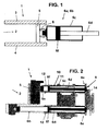
- a continuous casting mold 1 (FIG. 1) has a (rectangular) casting cavity 2, which from broad side plates 3 and 4 and arranged at the ends narrow side plates 5 is formed.
- For each narrow side plate 5 are in pairs one above the other arranged piston-cylinder units 6a, 6b (see also Fig. 6) provided to the Narrow side plates 5 in the casting direction by the angle C of the shrinkage or the Cast strand width W.
- the wide side plates 3, 4 and the narrow side plates 5 each consist of copper plates. 7
- At least the narrow side plates 5 are by means of a hinge 8 with the cylinder housing 6c hinged, while the piston rods 6d with their facing away End 6e are each held at a fixed point 9.
- the cylinder housing 6c can in a longitudinal guide 10 (FIGS. 2 and 3-5) a sliding movement relative to the piston rod 6d with the piston 6f (FIG. 1). the piston rod 6d can also be performed continuously to the piston-cylinder units 6a, 6b to operate as a synchronous cylinder, which in turn the cylinder housing 6a in the longitudinal guide 10 moves.
- a specific embodiment is shown, originally an electromechanical Adjustment 11 formed.
- This is as a longitudinal guide 10 for the Cylinder housing 6c, the guide 12 a quill (spindle guide of the electromechanical Adjustment 11) used, so the part of an electromechanical to be replaced Adjustment drive 11 for the copper plate 7 was.
- the existing guides 12 receive the replaced adjustment, wherein the cylinder housings 6c are constructed and manufactured in the outer dimensions become.
- This storage of the cylinder housing 6c in the existing longitudinal guide 10 allows the necessary freedom of movement of the cylinder housing 6c.
- the Piston rod 6d is attached to the existing fixed structure of the continuous casting machine fixed and represents the fixed point 9.
- the tensile forces in the casting direction, due to the strand movement, are in the longitudinal guide 10 (as for a previous electromechanical adjustment mechanism) intercepted. So there are no other design components for supporting shear forces required.
- Figs. 3 to 5 the individual positions of the adjustment are made visible.
- the cylinder housing 6c is retracted, i. the narrow side plate 5 is set to a large width of the cast strand.
- Fig. 4 is the Cylinder housing 6c extended, whereby the narrow side plate 5 on a small Width of the casting strand is set.
- a position sensor 13th can be arranged at the fixed point 9 and that the supply of hydraulic Pressure medium 14 can also be done in the fixed point 9.
- Fig. 6 is a control device 15 with a valve assembly 16 outside the area of the cylinder housing 6c arranged.
- the valve assembly 16 can also outside a cooling chamber following the continuous casting mold 1 or at rest Components are mounted outside of the Kokillen-oscillation device.
- the position sensors 13 are connected from the fixed point 9. However, the arrangement can also be from the side of the piston 6f forth in the piston-cylinder unit 6a, 6b be introduced.
- An arrangement of the position sensor 13 from outside the cylinder housing 6c of the piston-cylinder units 6a, 6b show FIGS. 3 to 5.
- Monitoring the pressure values via pressure sensors can be done directly on the cylinder housing 6c or behind a continuous valve 17 or 18 take place.
- the clamping of the narrow side plates 5 via the adaptation of the wide side plates 3, 4 by means of the usual springs and / or hydraulic cylinders.
- the clamping forces are determined so that in case of failure the Narrow side plates 5 can perform no change in position.
- the piston-cylinder units 6a, 6b for the narrow side plates 5 can at rest and or in case of failure, if no movement of the narrow side plate (s) are performed are to be switched off by means of the continuous valves 17 and 18 pressure.
Landscapes
- Engineering & Computer Science (AREA)
- Mechanical Engineering (AREA)
- Continuous Casting (AREA)
Abstract
Description
- Fig. 1
- einen Längsschnitt durch eine Grundausführung eines Anstellantriebs für eine Schmalseitenplatte der Stranggießkokille,
- Fig. 2
- denselben Längsschnitt für zwei Positionen des Anstellantriebs nach Umbau eines elektromechanischen Anstellantriebs in einen hydraulischen Anstellantrieb,
- Fig. 3-5
- jeweils Längsschnitte von verschiedenen Stellungen der Schmalseitenplatte mit zugehöriger Anstellantriebs-Position und
- Fig. 6
- ein Blockschaltbild der Steuerung oder Regelung für die zwei übereinanderliegenden hydraulischen Anstellantriebe der einen Schmalseitenplatte.
- 1
- Stranggießkokille
- 2
- Gießhohlraum
- 3
- Breitseitenplatte
- 4
- Breitseitenplatte
- 5
- Schmalseitenplatte
- 6a
- Kolben-Zylinder-Einheit
- 6b
- Kolben-Zylinder-Einheit
- 6c
- Zylindergehäuse
- 6d
- Kolbenstange
- 6e
- abgewandtes Ende
- 6f
- Kolben
- 7
- Kupferplatten
- 8
- Gelenk
- 9
- Festpunkt
- 10
- Längsführung
- 11
- Verstellantrieb
- 12
- Führung
- 13
- Positionsgeber
- 14
- hydraulisches Druckmittel
- 15
- Regeleinrichtung
- 16
- Ventilanordnung
- 17
- Stetigventil
- 18
- Stetigventil
Claims (6)
- Stranggießkokille (1) für flüssige Metalle, insbesondere für flüssigen Stahl, mit Verstellorganen für mehrere Kupferplatten (7), die den Gießhohlraum (2) umschließen, wobei die Verstellorgane aus paarweise übereinander angeordneten, hydraulischen Kolben-Zylinder-Einheiten (6a;6b) bestehen und die Kupferplatten (7) im Winkel (C) und / oder in der Gießstrangbreite (W) verstellbar sind,
dadurch gekennzeichnet, dass zumindest die Kokillenschmalseiten-Platten (5) jeweils an das Zylindergehäuse (6c) mit einem Gelenk (8) angeschlossen sind, die Kolbenstangen (6d) mit ihren abgewandten Enden (6e) jeweils an einem Festpunkt (9) gehalten sind und dass das Zylindergehäuse (6c) in einer Längsführung (10) für eine relative Schiebebewegung ausgebildet ist. - Stranggießkokille nach Anspruch 1,
dadurch gekennzeichnet, dass als Längsführung (10) des Zylindergehäuses (6c) die Führung (12) einer Pinole dient, die Bestandteil eines zu ersetzenden elektromechanischen Verstellantriebs (11) für die Kupferplatten (7) ist. - Stranggießkokille nach Anspruch 1,
dadurch gekennzeichnet, dass im Festpunkt (9) der Kolbenstange (6d) ein Positionsgeber (13) und /oder ein Anschluss für die Zuführung von hydraulischem Druckmittel (14) vorgesehen ist. - Stranggießkokille nach einem der Ansprüche 1 bis 3,
dadurch gekennzeichnet, dass eine Regeleinrichtung (15) vorgesehen ist mit einer Ventilanordnung (16) unmittelbar im Bereich des Zylindergehäuses (6c) oder außerhalb einer nachfolgenden Kühlkammer oder auf ruhenden Bauteilen der Stranggießvorrichtung. - Stranggießkokille nach einem der Ansprüche 3 oder 4,
dadurch gekennzeichnet, dass die Positionsgeber (13) von der Seite des Kolbens (6f) in der Kolben-Zylinder-Einheit (6a; 6b) her eingebracht sind. - Stranggießkokille nach einem der Ansprüche 3 bis 5,
dadurch gekennzeichnet, dass die Positionsgeber (13) von außerhalb des Zylindergehäuses (6c) der Kolben-Zylinder-Einheiten (6a; 6b) her angeschlossen sind.
Applications Claiming Priority (2)
| Application Number | Priority Date | Filing Date | Title |
|---|---|---|---|
| DE10326903 | 2003-06-14 | ||
| DE10326903A DE10326903A1 (de) | 2003-06-14 | 2003-06-14 | Hydraulische Schmalseitenverstellung für Brammen und Dünnbrammenstranggießanlagen |
Publications (2)
| Publication Number | Publication Date |
|---|---|
| EP1486273A1 true EP1486273A1 (de) | 2004-12-15 |
| EP1486273B1 EP1486273B1 (de) | 2008-04-16 |
Family
ID=33185796
Family Applications (1)
| Application Number | Title | Priority Date | Filing Date |
|---|---|---|---|
| EP04011889A Expired - Lifetime EP1486273B1 (de) | 2003-06-14 | 2004-05-19 | Stranggiesskokille mit Verstellorganen für mehrere Kupferplatten, die den Giesshohlraum umschliessen |
Country Status (3)
| Country | Link |
|---|---|
| EP (1) | EP1486273B1 (de) |
| AT (1) | ATE392281T1 (de) |
| DE (2) | DE10326903A1 (de) |
Cited By (7)
| Publication number | Priority date | Publication date | Assignee | Title |
|---|---|---|---|---|
| EP1703156A1 (de) * | 2005-03-19 | 2006-09-20 | SMS Demag AG | Kupplung aus zwei verstellbaren Steckteilen |
| WO2008131712A1 (de) * | 2007-04-26 | 2008-11-06 | Sms Siemag Ag | STRANGGIEßKOKILLE |
| AT519154A1 (de) * | 2016-09-26 | 2018-04-15 | Primetals Technologies Austria GmbH | Regelung der Schmalseitenkonizität einer Stranggusskokille |
| CN112453341A (zh) * | 2021-01-20 | 2021-03-09 | 东台市华裕机械配件有限公司 | 一种同步驱动式铜合金热顶铸造装置 |
| CN112872026A (zh) * | 2020-12-25 | 2021-06-01 | 天津市中重科技工程有限公司 | 一种大型h型钢轧制工艺中异形坯翼缘厚度的调整方法 |
| CN114774707A (zh) * | 2022-03-03 | 2022-07-22 | 云南钛业股份有限公司 | 一种结晶器、电子束冷床炉及其熔铸方法 |
| CN115229165A (zh) * | 2022-07-12 | 2022-10-25 | 泰兴市苏中自动化仪表有限公司 | 一种具有自动矫正功能的钢芯覆铜线连铸装置 |
Citations (4)
| Publication number | Priority date | Publication date | Assignee | Title |
|---|---|---|---|---|
| US5355936A (en) * | 1990-11-29 | 1994-10-18 | Kawasaki Jukogyo Kabushiki Kaisha | Adjustable mold for horizontal continuous casting apparatus |
| EP0914888A1 (de) * | 1997-10-31 | 1999-05-12 | Sms Schloemann-Siemag Aktiengesellschaft | Stranggiesskokille |
| DE19960792A1 (de) * | 1999-01-15 | 2000-08-17 | Voest Alpine Ind Anlagen | Stranggiesskokille |
| EP1262260A1 (de) * | 2001-05-31 | 2002-12-04 | Daido Tokushuko Kabushiki Kaisha | Verfahren und Vorrichtung zum vertikal Giessen von Rohblöcken und so hergestellter Rohblock |
-
2003
- 2003-06-14 DE DE10326903A patent/DE10326903A1/de not_active Withdrawn
-
2004
- 2004-05-19 AT AT04011889T patent/ATE392281T1/de active
- 2004-05-19 DE DE502004006814T patent/DE502004006814D1/de not_active Expired - Lifetime
- 2004-05-19 EP EP04011889A patent/EP1486273B1/de not_active Expired - Lifetime
Patent Citations (4)
| Publication number | Priority date | Publication date | Assignee | Title |
|---|---|---|---|---|
| US5355936A (en) * | 1990-11-29 | 1994-10-18 | Kawasaki Jukogyo Kabushiki Kaisha | Adjustable mold for horizontal continuous casting apparatus |
| EP0914888A1 (de) * | 1997-10-31 | 1999-05-12 | Sms Schloemann-Siemag Aktiengesellschaft | Stranggiesskokille |
| DE19960792A1 (de) * | 1999-01-15 | 2000-08-17 | Voest Alpine Ind Anlagen | Stranggiesskokille |
| EP1262260A1 (de) * | 2001-05-31 | 2002-12-04 | Daido Tokushuko Kabushiki Kaisha | Verfahren und Vorrichtung zum vertikal Giessen von Rohblöcken und so hergestellter Rohblock |
Cited By (9)
| Publication number | Priority date | Publication date | Assignee | Title |
|---|---|---|---|---|
| EP1703156A1 (de) * | 2005-03-19 | 2006-09-20 | SMS Demag AG | Kupplung aus zwei verstellbaren Steckteilen |
| WO2008131712A1 (de) * | 2007-04-26 | 2008-11-06 | Sms Siemag Ag | STRANGGIEßKOKILLE |
| AT519154A1 (de) * | 2016-09-26 | 2018-04-15 | Primetals Technologies Austria GmbH | Regelung der Schmalseitenkonizität einer Stranggusskokille |
| AT519154B1 (de) * | 2016-09-26 | 2019-12-15 | Primetals Technologies Austria GmbH | Regelung der Schmalseitenkonizität einer Stranggusskokille |
| CN112872026A (zh) * | 2020-12-25 | 2021-06-01 | 天津市中重科技工程有限公司 | 一种大型h型钢轧制工艺中异形坯翼缘厚度的调整方法 |
| CN112453341A (zh) * | 2021-01-20 | 2021-03-09 | 东台市华裕机械配件有限公司 | 一种同步驱动式铜合金热顶铸造装置 |
| CN114774707A (zh) * | 2022-03-03 | 2022-07-22 | 云南钛业股份有限公司 | 一种结晶器、电子束冷床炉及其熔铸方法 |
| CN115229165A (zh) * | 2022-07-12 | 2022-10-25 | 泰兴市苏中自动化仪表有限公司 | 一种具有自动矫正功能的钢芯覆铜线连铸装置 |
| CN115229165B (zh) * | 2022-07-12 | 2023-06-30 | 泰兴市苏中自动化仪表有限公司 | 一种具有自动矫正功能的钢芯覆铜线连铸装置 |
Also Published As
| Publication number | Publication date |
|---|---|
| EP1486273B1 (de) | 2008-04-16 |
| DE10326903A1 (de) | 2004-12-30 |
| DE502004006814D1 (de) | 2008-05-29 |
| ATE392281T1 (de) | 2008-05-15 |
Similar Documents
| Publication | Publication Date | Title |
|---|---|---|
| EP3212351B1 (de) | Strangführungsrolleneinheit für eine stranggiessmaschine | |
| DE4014905C2 (de) | Vorrichtung zum Schließen von Formen einer Spritzgießmaschine | |
| DE112015003090T5 (de) | Öffnungs-/Schliessvorrichtung und Formvorrichtung | |
| EP1486273B1 (de) | Stranggiesskokille mit Verstellorganen für mehrere Kupferplatten, die den Giesshohlraum umschliessen | |
| DE3235673A1 (de) | Plattenkokille zum stranggiessen | |
| EP2288457A1 (de) | Stranggiesskokille für eine stranggiessanlage | |
| EP2717826A1 (de) | Patienten-hubliege | |
| DE1528240C3 (de) | Hydraulische Einetagen-Heizpresse | |
| DE4444941C3 (de) | Stranggießkokille | |
| EP0770468A2 (de) | Holmlose Zwei-Platten-Spritzgiessmaschine | |
| DE2331318B2 (de) | Presse zur massivumformung, beispielsweise strang- oder schmiedepresse mit pressenrahmen in vorgespannter bauweise | |
| EP0043527B1 (de) | Horizontal-Druckgiessmaschine | |
| DE102013019270A1 (de) | Verstellkokille mit kleiner Masse zum Stahlgießen von 4 verschiedenen Quadratformaten mit 2 schwingungstechnisch entkoppelten Revolverköpfen | |
| EP2988889B1 (de) | Vorrichtung zum stranggiessen und verfahren zur montage dieser vorrichtung zum stranggiessen | |
| AT408853B (de) | Strangführung für eine stranggiessanlage | |
| DE3829549C2 (de) | ||
| EP1044745A1 (de) | Formschliesseinheit, insbesondere für eine Warmkammerdruckgiessmaschine | |
| EP3706933B1 (de) | Strangführungssegment und stranggiessanlage | |
| EP3914407B1 (de) | Verfahren zum betreiben einer giessmaschine und giessmaschine | |
| EP0783955B1 (de) | Zwei-Platten-Spritzgiessmaschine mit einer beweglichen und einer feststehenden Formaufspannplatte | |
| EP1025365B1 (de) | Linearmodul | |
| DE2702975A1 (de) | Vorrichtung zum ausziehen eines anfahrstranges und eines gusstranges | |
| DE202017107328U1 (de) | Druckgussform | |
| DE19960792A1 (de) | Stranggiesskokille | |
| AT401028B (de) | Stranggiesskokille |
Legal Events
| Date | Code | Title | Description |
|---|---|---|---|
| PUAI | Public reference made under article 153(3) epc to a published international application that has entered the european phase |
Free format text: ORIGINAL CODE: 0009012 |
|
| 17P | Request for examination filed |
Effective date: 20040519 |
|
| AK | Designated contracting states |
Kind code of ref document: A1 Designated state(s): AT BE BG CH CY CZ DE DK EE ES FI FR GB GR HU IE IT LI LU MC NL PL PT RO SE SI SK TR |
|
| AX | Request for extension of the european patent |
Extension state: AL HR LT LV MK |
|
| AKX | Designation fees paid |
Designated state(s): AT BE BG CH CY CZ DE DK EE ES FI FR GB GR HU IE IT LI LU MC NL PL PT RO SE SI SK TR |
|
| 17Q | First examination report despatched |
Effective date: 20071026 |
|
| GRAP | Despatch of communication of intention to grant a patent |
Free format text: ORIGINAL CODE: EPIDOSNIGR1 |
|
| GRAS | Grant fee paid |
Free format text: ORIGINAL CODE: EPIDOSNIGR3 |
|
| GRAA | (expected) grant |
Free format text: ORIGINAL CODE: 0009210 |
|
| AK | Designated contracting states |
Kind code of ref document: B1 Designated state(s): AT BE BG CH CY CZ DE DK EE ES FI FR GB GR HU IE IT LI LU MC NL PL PT RO SE SI SK TR |
|
| REG | Reference to a national code |
Ref country code: CH Ref legal event code: EP |
|
| REG | Reference to a national code |
Ref country code: IE Ref legal event code: FG4D Free format text: LANGUAGE OF EP DOCUMENT: GERMAN |
|
| REF | Corresponds to: |
Ref document number: 502004006814 Country of ref document: DE Date of ref document: 20080529 Kind code of ref document: P |
|
| PG25 | Lapsed in a contracting state [announced via postgrant information from national office to epo] |
Ref country code: SI Free format text: LAPSE BECAUSE OF FAILURE TO SUBMIT A TRANSLATION OF THE DESCRIPTION OR TO PAY THE FEE WITHIN THE PRESCRIBED TIME-LIMIT Effective date: 20080416 |
|
| NLV1 | Nl: lapsed or annulled due to failure to fulfill the requirements of art. 29p and 29m of the patents act | ||
| PG25 | Lapsed in a contracting state [announced via postgrant information from national office to epo] |
Ref country code: PT Free format text: LAPSE BECAUSE OF FAILURE TO SUBMIT A TRANSLATION OF THE DESCRIPTION OR TO PAY THE FEE WITHIN THE PRESCRIBED TIME-LIMIT Effective date: 20080916 Ref country code: NL Free format text: LAPSE BECAUSE OF FAILURE TO SUBMIT A TRANSLATION OF THE DESCRIPTION OR TO PAY THE FEE WITHIN THE PRESCRIBED TIME-LIMIT Effective date: 20080416 Ref country code: FI Free format text: LAPSE BECAUSE OF FAILURE TO SUBMIT A TRANSLATION OF THE DESCRIPTION OR TO PAY THE FEE WITHIN THE PRESCRIBED TIME-LIMIT Effective date: 20080416 Ref country code: ES Free format text: LAPSE BECAUSE OF FAILURE TO SUBMIT A TRANSLATION OF THE DESCRIPTION OR TO PAY THE FEE WITHIN THE PRESCRIBED TIME-LIMIT Effective date: 20080727 Ref country code: BG Free format text: LAPSE BECAUSE OF FAILURE TO SUBMIT A TRANSLATION OF THE DESCRIPTION OR TO PAY THE FEE WITHIN THE PRESCRIBED TIME-LIMIT Effective date: 20080716 |
|
| PG25 | Lapsed in a contracting state [announced via postgrant information from national office to epo] |
Ref country code: PL Free format text: LAPSE BECAUSE OF FAILURE TO SUBMIT A TRANSLATION OF THE DESCRIPTION OR TO PAY THE FEE WITHIN THE PRESCRIBED TIME-LIMIT Effective date: 20080416 |
|
| BERE | Be: lapsed |
Owner name: SMS DEMAG A.G. Effective date: 20080531 |
|
| REG | Reference to a national code |
Ref country code: IE Ref legal event code: FD4D |
|
| PG25 | Lapsed in a contracting state [announced via postgrant information from national office to epo] |
Ref country code: MC Free format text: LAPSE BECAUSE OF NON-PAYMENT OF DUE FEES Effective date: 20080531 |
|
| REG | Reference to a national code |
Ref country code: CH Ref legal event code: PL |
|
| PG25 | Lapsed in a contracting state [announced via postgrant information from national office to epo] |
Ref country code: IE Free format text: LAPSE BECAUSE OF FAILURE TO SUBMIT A TRANSLATION OF THE DESCRIPTION OR TO PAY THE FEE WITHIN THE PRESCRIBED TIME-LIMIT Effective date: 20080416 Ref country code: DK Free format text: LAPSE BECAUSE OF FAILURE TO SUBMIT A TRANSLATION OF THE DESCRIPTION OR TO PAY THE FEE WITHIN THE PRESCRIBED TIME-LIMIT Effective date: 20080416 Ref country code: LI Free format text: LAPSE BECAUSE OF NON-PAYMENT OF DUE FEES Effective date: 20080531 Ref country code: CH Free format text: LAPSE BECAUSE OF NON-PAYMENT OF DUE FEES Effective date: 20080531 Ref country code: SE Free format text: LAPSE BECAUSE OF FAILURE TO SUBMIT A TRANSLATION OF THE DESCRIPTION OR TO PAY THE FEE WITHIN THE PRESCRIBED TIME-LIMIT Effective date: 20080716 Ref country code: CZ Free format text: LAPSE BECAUSE OF FAILURE TO SUBMIT A TRANSLATION OF THE DESCRIPTION OR TO PAY THE FEE WITHIN THE PRESCRIBED TIME-LIMIT Effective date: 20080416 |
|
| PLBE | No opposition filed within time limit |
Free format text: ORIGINAL CODE: 0009261 |
|
| STAA | Information on the status of an ep patent application or granted ep patent |
Free format text: STATUS: NO OPPOSITION FILED WITHIN TIME LIMIT |
|
| EN | Fr: translation not filed | ||
| PG25 | Lapsed in a contracting state [announced via postgrant information from national office to epo] |
Ref country code: SK Free format text: LAPSE BECAUSE OF FAILURE TO SUBMIT A TRANSLATION OF THE DESCRIPTION OR TO PAY THE FEE WITHIN THE PRESCRIBED TIME-LIMIT Effective date: 20080416 Ref country code: RO Free format text: LAPSE BECAUSE OF FAILURE TO SUBMIT A TRANSLATION OF THE DESCRIPTION OR TO PAY THE FEE WITHIN THE PRESCRIBED TIME-LIMIT Effective date: 20080416 |
|
| 26N | No opposition filed |
Effective date: 20090119 |
|
| PG25 | Lapsed in a contracting state [announced via postgrant information from national office to epo] |
Ref country code: BE Free format text: LAPSE BECAUSE OF NON-PAYMENT OF DUE FEES Effective date: 20080531 |
|
| PG25 | Lapsed in a contracting state [announced via postgrant information from national office to epo] |
Ref country code: EE Free format text: LAPSE BECAUSE OF FAILURE TO SUBMIT A TRANSLATION OF THE DESCRIPTION OR TO PAY THE FEE WITHIN THE PRESCRIBED TIME-LIMIT Effective date: 20080416 |
|
| PG25 | Lapsed in a contracting state [announced via postgrant information from national office to epo] |
Ref country code: CY Free format text: LAPSE BECAUSE OF FAILURE TO SUBMIT A TRANSLATION OF THE DESCRIPTION OR TO PAY THE FEE WITHIN THE PRESCRIBED TIME-LIMIT Effective date: 20080416 |
|
| PG25 | Lapsed in a contracting state [announced via postgrant information from national office to epo] |
Ref country code: HU Free format text: LAPSE BECAUSE OF FAILURE TO SUBMIT A TRANSLATION OF THE DESCRIPTION OR TO PAY THE FEE WITHIN THE PRESCRIBED TIME-LIMIT Effective date: 20081017 Ref country code: LU Free format text: LAPSE BECAUSE OF NON-PAYMENT OF DUE FEES Effective date: 20080519 |
|
| PG25 | Lapsed in a contracting state [announced via postgrant information from national office to epo] |
Ref country code: TR Free format text: LAPSE BECAUSE OF FAILURE TO SUBMIT A TRANSLATION OF THE DESCRIPTION OR TO PAY THE FEE WITHIN THE PRESCRIBED TIME-LIMIT Effective date: 20080416 |
|
| PG25 | Lapsed in a contracting state [announced via postgrant information from national office to epo] |
Ref country code: GR Free format text: LAPSE BECAUSE OF FAILURE TO SUBMIT A TRANSLATION OF THE DESCRIPTION OR TO PAY THE FEE WITHIN THE PRESCRIBED TIME-LIMIT Effective date: 20080717 |
|
| PG25 | Lapsed in a contracting state [announced via postgrant information from national office to epo] |
Ref country code: FR Free format text: LAPSE BECAUSE OF FAILURE TO SUBMIT A TRANSLATION OF THE DESCRIPTION OR TO PAY THE FEE WITHIN THE PRESCRIBED TIME-LIMIT Effective date: 20090227 |
|
| REG | Reference to a national code |
Ref country code: DE Ref legal event code: R082 Ref document number: 502004006814 Country of ref document: DE Representative=s name: HEMMERICH & KOLLEGEN, DE Ref country code: DE Ref legal event code: R081 Ref document number: 502004006814 Country of ref document: DE Owner name: SMS GROUP GMBH, DE Free format text: FORMER OWNER: SMS SIEMAG AKTIENGESELLSCHAFT, 40237 DUESSELDORF, DE |
|
| PGFP | Annual fee paid to national office [announced via postgrant information from national office to epo] |
Ref country code: DE Payment date: 20200520 Year of fee payment: 17 |
|
| PGFP | Annual fee paid to national office [announced via postgrant information from national office to epo] |
Ref country code: IT Payment date: 20200528 Year of fee payment: 17 Ref country code: GB Payment date: 20200527 Year of fee payment: 17 |
|
| PGFP | Annual fee paid to national office [announced via postgrant information from national office to epo] |
Ref country code: AT Payment date: 20200522 Year of fee payment: 17 |
|
| REG | Reference to a national code |
Ref country code: DE Ref legal event code: R119 Ref document number: 502004006814 Country of ref document: DE |
|
| REG | Reference to a national code |
Ref country code: AT Ref legal event code: MM01 Ref document number: 392281 Country of ref document: AT Kind code of ref document: T Effective date: 20210519 |
|
| GBPC | Gb: european patent ceased through non-payment of renewal fee |
Effective date: 20210519 |
|
| PG25 | Lapsed in a contracting state [announced via postgrant information from national office to epo] |
Ref country code: AT Free format text: LAPSE BECAUSE OF NON-PAYMENT OF DUE FEES Effective date: 20210519 |
|
| PG25 | Lapsed in a contracting state [announced via postgrant information from national office to epo] |
Ref country code: GB Free format text: LAPSE BECAUSE OF NON-PAYMENT OF DUE FEES Effective date: 20210519 Ref country code: DE Free format text: LAPSE BECAUSE OF NON-PAYMENT OF DUE FEES Effective date: 20211201 |
|
| PG25 | Lapsed in a contracting state [announced via postgrant information from national office to epo] |
Ref country code: IT Free format text: LAPSE BECAUSE OF NON-PAYMENT OF DUE FEES Effective date: 20200519 |
|
| PG25 | Lapsed in a contracting state [announced via postgrant information from national office to epo] |
Ref country code: IT Free format text: LAPSE BECAUSE OF NON-PAYMENT OF DUE FEES Effective date: 20210519 |