EP1485215B1 - Einrichtung zum dämpfen von druckstössen von in einer flüssigkeitsleitung strömenden flüssigkeiten - Google Patents
Einrichtung zum dämpfen von druckstössen von in einer flüssigkeitsleitung strömenden flüssigkeiten Download PDFInfo
- Publication number
- EP1485215B1 EP1485215B1 EP03707889A EP03707889A EP1485215B1 EP 1485215 B1 EP1485215 B1 EP 1485215B1 EP 03707889 A EP03707889 A EP 03707889A EP 03707889 A EP03707889 A EP 03707889A EP 1485215 B1 EP1485215 B1 EP 1485215B1
- Authority
- EP
- European Patent Office
- Prior art keywords
- liquid
- conduit
- bypass
- pressure surges
- gas
- Prior art date
- Legal status (The legal status is an assumption and is not a legal conclusion. Google has not performed a legal analysis and makes no representation as to the accuracy of the status listed.)
- Expired - Lifetime
Links
Images




Classifications
-
- A—HUMAN NECESSITIES
- A61—MEDICAL OR VETERINARY SCIENCE; HYGIENE
- A61L—METHODS OR APPARATUS FOR STERILISING MATERIALS OR OBJECTS IN GENERAL; DISINFECTION, STERILISATION OR DEODORISATION OF AIR; CHEMICAL ASPECTS OF BANDAGES, DRESSINGS, ABSORBENT PADS OR SURGICAL ARTICLES; MATERIALS FOR BANDAGES, DRESSINGS, ABSORBENT PADS OR SURGICAL ARTICLES
- A61L2/00—Disinfection or sterilisation of materials or objects, in general; Accessories therefor
- A61L2/16—Disinfection or sterilisation of materials or objects, in general; Accessories therefor using chemical substances
- A61L2/18—Liquid substances
-
- B—PERFORMING OPERATIONS; TRANSPORTING
- B67—OPENING, CLOSING OR CLEANING BOTTLES, JARS OR SIMILAR CONTAINERS; LIQUID HANDLING
- B67C—CLEANING, FILLING WITH LIQUIDS OR SEMILIQUIDS, OR EMPTYING, OF BOTTLES, JARS, CANS, CASKS, BARRELS, OR SIMILAR CONTAINERS, NOT OTHERWISE PROVIDED FOR; FUNNELS
- B67C3/00—Bottling liquids or semiliquids; Filling jars or cans with liquids or semiliquids using bottling or like apparatus; Filling casks or barrels with liquids or semiliquids
- B67C3/001—Cleaning of filling devices
-
- Y—GENERAL TAGGING OF NEW TECHNOLOGICAL DEVELOPMENTS; GENERAL TAGGING OF CROSS-SECTIONAL TECHNOLOGIES SPANNING OVER SEVERAL SECTIONS OF THE IPC; TECHNICAL SUBJECTS COVERED BY FORMER USPC CROSS-REFERENCE ART COLLECTIONS [XRACs] AND DIGESTS
- Y10—TECHNICAL SUBJECTS COVERED BY FORMER USPC
- Y10T—TECHNICAL SUBJECTS COVERED BY FORMER US CLASSIFICATION
- Y10T137/00—Fluid handling
- Y10T137/2931—Diverse fluid containing pressure systems
- Y10T137/3115—Gas pressure storage over or displacement of liquid
- Y10T137/3118—Surge suppression
-
- Y—GENERAL TAGGING OF NEW TECHNOLOGICAL DEVELOPMENTS; GENERAL TAGGING OF CROSS-SECTIONAL TECHNOLOGIES SPANNING OVER SEVERAL SECTIONS OF THE IPC; TECHNICAL SUBJECTS COVERED BY FORMER USPC CROSS-REFERENCE ART COLLECTIONS [XRACs] AND DIGESTS
- Y10—TECHNICAL SUBJECTS COVERED BY FORMER USPC
- Y10T—TECHNICAL SUBJECTS COVERED BY FORMER US CLASSIFICATION
- Y10T137/00—Fluid handling
- Y10T137/4238—With cleaner, lubrication added to fluid or liquid sealing at valve interface
- Y10T137/4245—Cleaning or steam sterilizing
- Y10T137/4259—With separate material addition
-
- Y—GENERAL TAGGING OF NEW TECHNOLOGICAL DEVELOPMENTS; GENERAL TAGGING OF CROSS-SECTIONAL TECHNOLOGIES SPANNING OVER SEVERAL SECTIONS OF THE IPC; TECHNICAL SUBJECTS COVERED BY FORMER USPC CROSS-REFERENCE ART COLLECTIONS [XRACs] AND DIGESTS
- Y10—TECHNICAL SUBJECTS COVERED BY FORMER USPC
- Y10T—TECHNICAL SUBJECTS COVERED BY FORMER US CLASSIFICATION
- Y10T137/00—Fluid handling
- Y10T137/8593—Systems
- Y10T137/87265—Dividing into parallel flow paths with recombining
- Y10T137/87338—Flow passage with bypass
- Y10T137/87362—Including cleaning, treating, or heat transfer feature
Definitions
- the invention relates to a device for damping pressure surges of liquids flowing in a liquid line according to the preamble of claim 1.
- liquids When transporting liquids through liquid lines, especially for the purpose of filling in containers, the liquids must be brought to certain flow values by means of control and / or regulating valves in their flow or the flow of liquids must be interrupted, e.g. after reaching a predetermined level in the container. It therefore comes in the liquid lines constantly to more or less large pressure fluctuations. These can be very significant and have a pulsating characteristic in large filling systems, for example when bottling beer, milk, etc.
- Pressure surges can give maximum pressures in excess of two and a half times the normal fluid line pressure.
- the fittings and other apparatus such.
- Membrane filters, plate heat exchangers and above all seals overstressed.
- pressure surges are classified as even more critical according to the fatigue test.
- air chambers for damping the pressure surges.
- air chambers are a proven and simple damping device, but different pressures in the liquid lines cause different sized gas chambers in the air chamber with different natural frequencies, which can cause problems for downstream electronic controls.
- Another major disadvantage of such air chambers is that cleaning during an operating cycle is not possible. A cleaning of a wind boiler requires a shut-off of the same from the pipeline, after cleaning the risk of the presence of residues of the cleaning agent can not be excluded. A complete flush of the air chamber is only time consuming feasible.
- Utility Model AT 001740 U1 discloses a shunt conduit, i. a bypass line, known to a liquid line, such as a beer pipe, which is filled with gas in the normal state and serves to absorb pressure surges.
- a shunt conduit i. a bypass line
- a liquid line such as a beer pipe
- pressure surges can penetrate through the bypass line.
- a cleaning, especially with a sterilizing liquid stir cumbersome, because on the one hand the bypass line and the other liquid line to be treated separately, and further there is a product change to difficulties due to improper mixing of successively flowing through the liquid line different products.
- the invention aims to avoid these disadvantages and difficulties and has set itself the task of creating a device of the type described above, which not only allows excellent damping of pressure surges, but also allows reliable cleaning of the device, u.zw, by simple means , so that the application also for bio-sensitive products, such as Food products, without requiring a great deal of effort, is given. In addition, a product change without substantial mixing of different products should be feasible.
- an emptying cock is provided in each case adjacent to the bypass line of the liquid line separating shut-off valves and within the sections formed by the shut-off valves in the bypass line in each case.
- a sterilizing liquid is preferably provided.
- the device according to the invention can be used to a particularly high degree for biologically endangered products, in particular food products.
- probes for detecting a liquid level are preferably provided in the bypass line at a predetermined distance from the first and second shut-off valves, where appropriate, a control unit is provided which is coupled to at least one of the gas supply lines to the bypass line is, so that when displaying a liquid level, an automatic gas purging and thus a discharge of liquid from the bypass line takes place.
- FIG. 1 shows a bottling plant for fresh milk in a schematic representation.
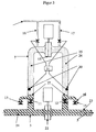
- Fig. 2 shows the device according to the invention in detail again.
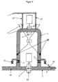
- FIGS. 3 to 5 illustrate various operating states of the device according to the invention.
- Fig. 6 shows a variant of this device again.
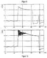
- pressure surges occurring in the fluid line are illustrated in diagram form, u. between in Figs. 7 and 9 with inventive device and in Figs. 8 and 10 without inventive device.
- the device 6 has a bypass line 7, which bridges a predetermined section 8 of the liquid line 3.
- the bypass line 7 is provided with a first and a second shut-off valve 11, 12, so that it is possible, the bypass line 7 line completely from the liquid line separate.
- a third shut-off valve 15 is located in the bypass line 7 at approximately the same distance from the mouths of the bypass line 7 (at 9 and 10, respectively) ) in the liquid line.
- shut-off gas supply lines 16, 17 are provided in the bypass line.
- probes 20 are provided in this at the predetermined distance 19 of the first and second shut-off valve, with which the presence of liquid in the level of the probes 20 can be determined. If these probes 20 are flooded with liquid, these probes 20 emit a signal which controls the admission of a gas via the gas supply lines 16 or 17 into the corresponding flooded section of the bypass line 7 via a control unit 21.
- a fourth shut-off valve 22 is installed in the section 8, which is bridged by the bypass line 7, which shuts off the main flow, ie, the liquid flow via the liquid line 3 to the filling machines 4 or the like.
- This valve 22 is either as a shut-off valve ( Figure 2) or as Control valve, as shown in Fig. 6, formed.
- the slide is preferably provided with a hole, this hole, for example, has a diameter of a few millimeters to 20 mm. As a result, a low flow of the flowing medium in the fluid line is ensured, even if the valve is closed. This hole thus forms a flow opening releasing the leakage opening.
- a throttle 23 in the flow direction.
- the function of the device 6 according to the invention is the following:
- the first and second shut-off valves 11, 12 are opened and the drainage taps 13, 14 are closed.
- the bypass line 7 in which the third shut-off valve 15 is closed, located in the two spaces formed by the closed third valve 25, 26 gas cushion, u. zw. in the manner that the liquid level 27 is below the provided in these spaces 25, 26 probes 20.
- the fourth shut-off valve 22 is opened. When pressure surges or high-frequency pressure fluctuations occur, these are absorbed or decomposed by gas pockets present in the two gas-filled spaces 25, 26 of the bypass line 7.
- CO 2 or sterile air is used for generating a gas cushion.
- the gas pressure of the gas cushion is adapted to the prevailing static operating pressure of the liquid such that the liquid level 27 always remains below the probes 20. This condition is shown in FIG.
- the liquid line 3, the first and second shut-off valves 11, 12 remain open, however, the third shut-off valve 15 is opened and the fourth shut-off valve 22 is closed.
- the two discharge valves 13. 14 are briefly opened or clocked to remove from the pipeline parts leading from the bypass line 7 to the drain valves 13, 14, also to remove the previously funded liquid 24 and to fill these pipes with a cleaning medium 28 and to flow through.
- the gas supply lines are also briefly opened or clocked (see Fig. 4).
- both the liquid line 3 and the Bypass line 7 flows through the cleaning medium.
- the throttle 23 provides a Druckletonabfang at flows of liquid or subsequently flowing water.
- first the first and second shut-off valves 11, 12 are closed, the drain valves 13, 14 are opened and the portion between the first and the second shut-off valves 11, 12 of the bypass line 7 is flooded with gas.
- the third shut-off valve 15 is suitably closed.
- the fourth shut-off valve 22 is open, so that now after the cleaning liquid through the Flusstechniks effet new incoming liquid displaces this.
- the first and second shut-off valve 11, 12 are opened and the drain valves 13, 14 are closed, so that in turn the normal state shown in Fig. 3 is produced during the conveyance of the liquid via the liquid line 3. Analogously, the transition from the conveying of a product liquid to another product liquid is proceeded.
- FIGS. 7 to 10 it can be seen from the diagrams of FIGS. 7 to 10 to what extent pressure surges can be damped with the device according to the invention.
- Fig. 7 shows a damped pressure surge at normal stop of fluid delivery, i.e.. With electronic damping and Fig. 8, the pressure curve also at normal stop, but without inventive device 6. It is not only a much higher maximum pressure to recognize, but also a high frequency of only slowly decaying pressure oscillations, which lead to an enormous burden on the entire system ,
- FIGS. 9 and 10 show similar diagrams for an emergency stop of the liquid to be conveyed, and the like. Between FIG. 9 with device 6 according to the invention and FIG. 10 without device 6 according to the invention.
- the invention is not limited to the embodiments shown in the drawing, but can be modified in various ways.
- a bypass line any outgoing from a point of the liquid line 3 and elsewhere in the liquid line 3 opening pipe or possibly also a piping system understood with the same function.
- the liquid line 3 may be formed as a piping system.
Landscapes
- Health & Medical Sciences (AREA)
- Public Health (AREA)
- Chemical & Material Sciences (AREA)
- Chemical Kinetics & Catalysis (AREA)
- Epidemiology (AREA)
- Life Sciences & Earth Sciences (AREA)
- Animal Behavior & Ethology (AREA)
- General Chemical & Material Sciences (AREA)
- Veterinary Medicine (AREA)
- General Health & Medical Sciences (AREA)
- Food Preservation Except Freezing, Refrigeration, And Drying (AREA)
- Pipeline Systems (AREA)
- Basic Packing Technique (AREA)
- Organic Low-Molecular-Weight Compounds And Preparation Thereof (AREA)
- Pipe Accessories (AREA)
- Gas Separation By Absorption (AREA)
Description
- Die Erfindung betrifft eine Einrichtung zum Dämpfen von Druckstaßen von in einer Flüssigkeitsleitung strömenden Flüssigkeiten gemäß dem Oberbegriff des Anspruches 1.
- Beim Transportieren von Flüssigkeiten durch Flüssigkeitsleitungen, insbesondere zum Zweck des Abfüllens in Behältnisse, müssen die Flüssigkeiten durch Steuer- und/oder Regelungsventile in ihrem Fluß auf bestimmte Durchflußwerte gebracht werden bzw. muß der Fluß der Flüssigkeiten unterbrochen werden, z.B. nach Erreichen eines vorbestimmten Füllstandes im Behältnis. Es kommt daher in den Flüssigkeitsleitungen andauernd zu mehr oder weniger großen Druckschwankungen. Diese können sehr erheblich sein und bei großen Abfüllanlagen, beispielsweise beim Abfüllen von Bier, Milch, etc., eine pulsierende Charakteristik aufweisen.
- Druckstöße können Maximaldrücke von über dem Zweieinhalbfachen des normalen Flüssigkeitsleitungsdruckes ergeben. Hierdurch werden die Armaturen und sonstigen Apparate, wie z.B. Membranfilter, Plattenwärmetauscher sowie vor allem auch Dichtungen überbeansprucht. Bei höheren statischen Leitungsdrücken sind solche Druckstöße entsprechend der Dauerfestigkeitshypothese als noch kritischer einzustufen.
- Zur Abhilfe ist es bekannt, Windkessel zur Dämpfung der Druckstöße einzusetzen. Solche Windkessel sind zwar eine bewährte und einfache Dämpfungseinrichtung, jedoch bedingen unterschiedliche Drücke in den Flüssigkeitsleitungen unterschiedlich große Gasräume im Windkessel mit unterschiedlichen Eigenfrequenzen, was für nachgeschaltete elektronische Regelungen Probleme ergeben kann. Ein weiterer großer Nachteil solcher Windkessel ist, daß eine Reinigung während eines Betriebszyklus nicht möglich ist. Eine Reinigung eines Windkessels bedingt eine Absperrung desselben von der Rohrleitung, wobei nach der Reinigung die Gefahr des Vorhandenseins von Resten des Reinigungsmittels nicht ausgeschlossen werden kann. Eine Komplettspülung des Windkessels ist nur zeitraubend durchführbar.
- Man hat auch versucht, mit elektronischen Methoden Druckstöße zu dämpfen, d.h. elektronische Regel- und Dämpfungseinnchtungen vorzusehen. Diese sind jedoch von der Schnelligkeit der Systemsensorik und -aktorik abhängig. Es kann trotzdem vor allem bei hochfrequenten Schwingungen zu Resonanzen kommen, die das Problem der Druckstöße oft noch verschärfen. Anderseits kann auch eine Überdämpfung des Systems zu nicht mehr ausgleichbaren Druckschwankungen führen. Ein besonderes Problem stellt hierbei das Auftreten von stark unterschiedlichen Frequenzen der Druckstöße dar.
- Aus der Gebrauchsmusterschrift AT 001740 U1 ist eine Nebenschlussrohrleitung, d.h. eine Bypass-Leitung, zu einer Flüssigkeitsleitung, wie einer Bierleitung, bekannt, die im Normalzustand mit Gas gefüllt ist und zur Aufnahme von Druckstößen dient. Bei dieser bekannten Einrichtung können jedoch Druckstöße durch die Bypass-Leitung durchschlagen. Weiters ist eine Reinigung, insbesondere mit einer Sterilisationsflüssigkeit, umständlich durchzurühren, da einerseits die Bypass-Leitung und andererseits die Flüssigkeitsleitung getrennt zu behandeln sind, und weiters kommt es bei einem Produktwechsel zu Schwierigkeiten infolge einer unzulässigen Vermischung der nacheinander durch die Flüssigkeitsleitung strömenden unterschiedlichen Produkte.
- Aus der DE 197 06 578 C2 ist eine Einrichtung zum Dämpfen von Druckstößen von in einer Flüssigkeitsleitung strömenden Flüssigkeiten gemäß dem Oberbegriff des Anspruches 1 bekannt. Gemäß dieser Einrichtung gelingt es im Bypass einen Gaspolster auszubilden, der Druckschwankungen, die in der Flüssigkeitsleitung auftreten, ausgleichen kann. Der Bypass bildet hierbei einen einzigen Gasraum zur Pufferung der Druckstöße
- Die Erfindung bezweckt die Vermeidung dieser Nachteile und Schwierigkeiten und stellt sich die Aufgabe, eine Einrichtung der eingangs beschriebenen Art zu schaffen, welche nicht nur eine hervorragende Dämpfung von Druckstößen ermöglicht, sondern auch eine zuverlässige Reinigung der Einrichtung ermöglicht, u.zw, mit einfachen Mitteln, sodaß die Anwendung auch für biologisch gefährdete Produkte, wie z.B. Lebensmittelprodukte, ohne einen großen Aufwand zu erfordern, gegeben ist. Zudem soll auch ein Produktwechsel ohne wesentliche Mischung der unterschiedlichen Produkte durchführbar sein.
- Diese Aufgabe wird erfindungsgemäß durch die im kennzeichnenden Teil des Anspruches 1 enthaltenen Merkmale gelöst.
- Hierdurch gelingt es, ein Überströmen des Bypasses durch Flüssigkeit mit Sicherheit zu verhindern, d.h. die Gaspolster im Bypass bei jeder Art von Störung aufrecht zu erhelten. Zudem wird ein gegebenenfalls vorgesehenes Regelventil geschont. Ein aus dem Bypass entweichender und in die Flüssigkeitsleitung gelangender Gaspolster würde z.B. eine Filteraktivität eines Filters, das zum Filtern der Flüssigkeit vorgesehen ist, verringern, und es würde eine undefinierbare Gasmenge abgehen.
- Vorzugsweise ist jeweils benachbart zu die Bypass-Leitung von der Flüssigkeitsleitung trennenden Absperrventilen und innerhalb der von den Absperrventilen gebildeten Abschnitte in der Bypass-Leitung jeweils ein Entleerhahn vorgesehen.
- Hierdurch gelingt es, einen Produktwechsel ohne Reinigung exakt durchzuführen. Ein vom bisher strömenden Produkt unterschiedliches Produkt gelangt bis zur Füllstation, wird dort gestoppt, worauf die Absperrventile der Bypass-Leitung geschlossen werden und die Entleerhähne der Bypass-Leitung so lange geöffnet werden, bis das erste Produkt völlig abgelassen ist.
- Vorteilhaft weist das in der Füssigkeitsleitung vorgesehene Absperrventil im geschlossenen Zustand eine einen geringen Durchfluß ermöglichende Leckageöffnung auf und sind zweckmäßig das in der Flüssigkeitsleitung und in der Bypass-Leitung vorgesehene Absperrventil mittels einer Steuereinheit alternativ betätigbar.
- Als Reinigungsmedium ist vorzugsweise eine Sterilisationsflüssigkeit vorgesehen. Die erfindungsgemäße Einrichtung ist in besonders hohem Maße für biologisch gefährdete Produkte, insbesondere Lebensmittelprodukte, einsetzbar.
- Zur Sicherung eines Flüssigkeitsniveaus, d.h. zwecks Verhinderns des Ansteigens desselben über ein vorbestimmtes Ausmaß, sind vorzugsweise in der Bypass-Leitung im vorbestimmten Abstand vom ersten und vom zweiten Absperrventil Sonden zum Feststellen eines Flüssigkeitsstandes vorgesehen wobei zweckmäßig eine Steuerungseinheit vorgesehen ist, die mit mindestens einer der Gaszuführungsleitungen zur Bypass-Leitung gekoppelt ist, sodaß bei Anzeigen eines Flüssigkeitsstandes eine automatische Gasspülung und damit ein Abführen von Flüssigkeit aus der Bypass-Leitung stattfindet.
- Die Erfindung ist nachfolgend anhand der Zeichnung, in der ein Ausführungsbeispiel dargestellt ist, näher erläutert. Fig. 1 zeigt eine Abfüllanlage für Frischmilch in schematischer Darstellung. Fig. 2 gibt die erfindungsgemäße Einrichtung im Detail wieder. Die Fig. 3 bis 5 veranschaulichen verschiedene Betriebszustände der erfindungsgemäßen Einrichtung. Fig. 6 gibt eine Variante dieser Einrichtung wieder. In den Fig. 7 bis 10 sind in der Flüssigkeitsleitung auftrerende Druckstöße in Diagrammform veranschaulicht, u. zw. in den Fig. 7 und 9 mit erfindungsgemäßer Einrichtung und in den Fig. 8 und 10 ohne erfindungsgemäße Einrichtung.
- Gemäß der in Fig. 1 dargestellten Abfüllanlage für eine Flüssigkeit, hier für Frischmilch, gelangt Frischmilch von einem Vorratstank 1 über eine Zuführpumpe 2 und eine Flüssigkeitsleitung 3 zu zwei Abfüllmaschinen 4, in denen taktweise Milchflaschen oder sonstige Behältnisse, wie laminierte Kartons etc., befüllt werden. Zwischen dem Frischmilchtank und der ersten in Strömungsrichtung 5 angeordneten Abfüllanlage ist eine erfindungsgemäße Einrichtung 6 vorgesehen, die in Fig. 1 nur schematisch angedeutet ist, die jedoch in Fig. 2 im Detail dargestellt ist. Diese Einrichtung 6 ist zweckmäßig knapp vor den Abfüllmaschine 4 in die Flüssigkeitsleitung eingebaut.
- Gemäß der in Fig. 2 dargestellten Ausführungsform weist die erfindungsgemäße Einrichtung 6 eine Bypass-Leitung 7 auf, die einen vorbestimmten Abschnitt 8 der Flüssigkeitsleitung 3 überbrückt. Im Bereich der Einmündungen 9 und 10 der Bypass-Leitung 7 in die Flüssigkeitsleitung 3 ist die Bypass-Leitung 7 mit einem ersten und einem zweiten Absperrventil 11, 12 versehen, sodaß es möglich ist, die Bypass-Leitung 7 leitungsmäßig komplett von der Flüssigkeitsleitung zu trennen.
- Benachbart zum ersten und zum zweiten Absperrventil 11, 12 sind in der Bypass-Leitung jeweils ein absperrbarer Entleerhahn 13, 14 vorgesehen, u.zw. innerhalb des von den ersten und zweiten Absperrventilen 11, 12 gebildeten Abschnitts der Bypass-Leitung 7. Ein drittes Absperrventil 15 befindet sich in der Bypass-Leitung 7 in etwa dem gleichen Abstand von den Mündungen der Bypass-Leitung 7 (bei 9 bzw. 10) in die Flüssigkeitsleitung 3.
- In Strömungsrichtung 5 der Flüssigkeit vor und nach dem dritten Absperrventil 15 sind in die Bypass-Leitung 7 einmündende absperrbare Gaszuführungsleitungen 16, 17 vorgesehen.
- Zur Vermeidung eines zu hohen Flüssigkeitsniveaus in der Bypass-Leitung 7 sind in dieser im vorbestimmten Abstand 19 des ersten und zweiten Absperrventils Sonden 20 vorgesehen, mit denen das Vorhandensein von Flüssigkeit in dem Niveau der Sonden 20 festgestellt werden kann. Werden diese Sonden 20 von Flüssigkeit überspült, geben diese Sonden 20 ein Signal ab, welches über eine Steuereinheit 21 den Zutritt eines Gases über die Gaszuführungsleitungen 16 oder 17 in den entsprechenden überfluteten Abschnitt der Bypass-Leitung 7 steuern.
- In der Flüssigkeitsleitung 3 ist in dem Abschnitt 8, der von der Bypass-Leitung 7 überbrückt ist, ein viertes Absperrventil 22 eingebaut, welches den Hauptstrom, d.h. den Flüssigkeitsstrom der über die Flüssigkeitsleitung 3 zu den Abfüllmaschinen 4 oder dgl. geführt wird, absperrt. Dieses Ventil 22 ist entweder als Absperrventil (Fig.2) oder als Regelventil, wie in Fig. 6 dargestellt, ausgebildet. Bei einer Ausbildung als Absperrventil, z.B. verwirklicht als Hahnschieber, ist der Schieber vorzugsweise mit einem Loch versehen, wobei dieses Loch beispielsweise einen Durchmesser von einigen wenigen Millimetern bis 20 mm aufweist. Hierdurch wird ein geringes Weiterströmen des in der Flüssigkeitsleitung strömenden Mediums gewährleistet, auch wenn das Ventil geschlossen ist. Dieses Loch bildet somit eine den Durchfluß freilassende Leckageöffnung. In der Flüssigkeitsleitung ist weiters in Strömungsrichtung nach der Bypass-Leitung 7 eine Drossel 23 eingebaut.
- Die Funktion der erfindungsgemäßen Einrichtung 6 ist folgende:
- Während des normalen Förderns von Flüssigkeit 24 (Fig. 3) über die Flüssigkeitsleitung 3 sind die ersten und zweiten Absperrventile 11, 12 geöffnet und die Entleethähne 13, 14 geschlossen. In der Bypass-Leitung 7, in der das dritte Absperrventil 15 geschlossen ist, befinden sich in den beiden durch das geschlossene dritte Ventil gebildeten Räumen 25, 26 Gaspolster, u. zw. in der Art und Weise, daß das Flüssigkeitsniveau 27 unter den in diesen Räumen 25, 26 vorgesehenen Sonden 20 liegt. Während des Förderns der Flüssigkeit 24 ist das vierte Absperrventil 22 geöffnet. Bei Auftreten von Druckstößen oder hochfrequenten Druckschwankungen werden diese von in den beiden gasgefüllten Räumen 25, 26 der Bypass-Leitung 7 vorhandenen Gaspolstern aufgenommen bzw. abgebaut.
- Zum Erzeugen eines Gaspolsters wird vorzugsweise CO2 oder Sterilluft verwendet.
- Der Gasdruck der Gaspolster ist an den herrschenden statischen Betriebsdruck der Flüssigkeit derart angepaßt, daß das Flüssigkeitsniveau 27 stets unter den Sonden 20 verbleibt. Dieser Zustand ist in Fig. 3 dargestellt.
- Zum Zweck der Reinigung (Fig. 4) der Flüssigkeitsleitung 3 bleiben die ersten und zweiten Absperrventile 11, 12 geöffnet es werden jedoch das dritte Absperrventil 15 geöffnet und das vierte Absperrventil 22 geschlossen. Die beiden Entleerhähne 13. 14 werden kurzzeitig geöffnet bzw. getaktet, um aus den Rohrleitungsteilen, die von der Bypass-Leitung 7 zu den Entleerhähnen 13, 14 führen, ebenfalls die zuvor geförderte Flüssigkeit 24 zu entfernen und diese Rohrleitungen mit einem Reinigungsmedium 28 zu füllen und zu durchströmen. Die Gaszuführungsleitungen werden ebenfalls kurzzeitig geöffnet oder getaktet (vgl. Fig. 4).
- Infolge der Leckageöffnung des Absperrventiles 22 bzw. eines nicht zur Gänze geschlossenen Absperrventiles nach Fig. 6 wird sowohl die Flüssigkeitsleitung 3 als auch die Bypass-Leitung 7 vom Reinigungsmedium durchströmt. Die Drossel 23 sorgt für einen Druckstoßabfang bei Strömen der Flüssigkeit oder nachfolgend fließendem Wasser.
- Anstelle eines gleichzeitigen Durchströmens der Flüssigkeitsleitung 3 und der Bypass-Leitung 7 ist es auch möglich, während des Reinigungszyklus die Absperrventile 15 und 22 alternativ pulsierend zu öffnen und zu schließen, so daß das Reinigungsmedium die Leitungen 3 und 7 stoßweise pulsierend durchströmt.
- Um einen Produktwechsel durchführen zu können, d.h. z.B. die Reinigungsflüssigkeit vollständig zu entfernen, werden zunächst die ersten und zweiten Absperrventile 11, 12 geschlossen, die Entleerhähne 13, 14 geöffnet und der Abschnitt zwischen den ersten und den zweiten Absperrventilen 11, 12 der Bypass-Leitung 7 mit Gas geflutet. Hierbei ist zweckmäßig das dritte Absperrventil 15 geschlossen. Das vierte Absperrventil 22 ist geöffnet, sodaß die nunmehr nach der Reinigungsflüssigkeit durch die Flussigkeitsleitung neu einströmende Flüssigkeit diese verdrängt. Nach Entfernung der Reinigungsflüssigkeit werden das erste und das zweite Absperrventil 11, 12 geöffnet und die Entleerhähne 13, 14 geschlossen, sodaß wiederum der in Fig. 3 dargestellte Normalzustand während des Förderns der Flüssigkeit über die Flüssigkeitsleitung 3 hergestellt ist. Analog wird beim Übergang des Förderns einer Produktflüssigkeit zu einer anderen Produktflüssigkeit vorgegangen.
- Aus den Diagrammen der Fig. 7 bis 10 ist zu erkennen, in welchem Ausmaß Druckstöße mit der erfindungsgemäßen Einrichtung gedämpft werden können. So zeigt Fig. 7 beispielsweise einen gedämpften Druckstoß bei Normalstop der Flüssigkeitsförderung d.h. mit elektronischer Dämpfung und Fig. 8 den Druckverlauf ebenfalls bei Normalstop, jedoch ohne erfindungsgemäße Einrichtung 6. Es ist nicht nur ein deutlich höherer Maximaldruck zu erkennen, sondern auch eine hohe Frequenz der nur langsam abklingenden Druckschwingungen, die zu einer enormen Belastung der gesamten Anlage führen.
- Die Fig. 9 und 10 zeigen ähnliche Diagramme für einen Schnell- bzw. Notstop der zu fördernden Flüssigkeit, u. zw. Fig. 9 mit erfindungsgemäßer Einrichtung 6 und Fig. 10 ohne erfindungsgemäße Einrichtung 6.
- Die Erfindung beschränkt sich nicht auf die in der Zeichnung dargestellten Ausführungsbeispiele, sondern kann in verschiedener Hinsicht modifiziert werden. So wird als Bypass-Leitung jedwede von einer Stelle der Flüssigkeitsleitung 3 ausgehende und an anderer Stelle der Flüssigkeitsleitung 3 einmündende Rohrleitung oder gegebenenfalls auch ein Rohrleitungssystem mit gleicher Funktion verstanden. Desgleichen kann auch die Flüssigkeitsleitung 3 als Rohrleitungssystem ausgebildet sein.
Claims (6)
- Einrichtung (6) zum Dämpfen von Druckstößen von in einer Flüssigkeitsleitung (3) strömenden Flüssigkeiten (24), z.B. einer biologisch gefährdeten Flüssigkeit, sowie zum Reinigen, insbesondere zum Sterilisieren, der Flüssigkeitsleitung (3) mit einer einen Abschnitt (8) der Flüssigkeitsleitung (3) überbrückenden Bypass-Leitung (7), wobei ein Absperrventil (22) in der Flüssigkeitsleitung (3) zwischen den Einmündungen (9, 10) der Bypass-Leitung (7) sowie eine in die Bypass-Leitung (7) einmündende absperrbare Gaszuführungsleitung (16, 17) vorgesehen sind, dadurch gekennzeichnet, daß die Bypass-Leitung (7) wahlweise in zwei gasgefüllte Räume (25, 26), in die jeweils eine eigene Gaszuführungsleitung (16, 17) mündet, vorzugsweise zwei etwa volumsgleiche gasgefüllte Räume (25, 26), mittels eines Absperrventils (15) teilbar ist, die beide mit der Flüssigkeitsleitung (3) zwecks Dämpfens von Druckstößen kommunizieren.
- Einrichtung nach Anspruch 1, dadurch gekennzeichnet, daß jeweils benachbart zu die Bypass-Leitung (7) von der Flüssigkeitsleitung (3) trennenden Absperrventilen (11 bzw. 12) und innerhalb der von den Absperrventilen (11, 12) gebildeten Abschnitte in der Bypass-Leitung (7) jeweils ein Entleerhahn (13, 14) vorgesehen ist.
- Einrichtung nach Anspruch 1 oder 2, dadurch gekennzeichnet, daß das in der Füssigkeirsleitung (3) vorgesehene Absperrventil (22) im geschlossenen Zustand eine einen geringen Durchfluß ermöglichende Leckageöffnung aufweist.
- Einrichtung nach einem oder mehreren der Ansprüche 1 bis 3, dadurch gekennzeichnet, daß das die Bypass-Leitung (7) teilende und das in der Flüssigkeitsleitung (3) vorgesehene Absperrventil (15, 22) mittels einer Steuereinheit alternativ betätigbar ist.
- Einrichtung nach einem oder mehreren der Ansprüche 1 bis 4. dadurch gekennzeichnet, daß in der Bypass-Leitung (7) im vorbestimmten Abstand vom ersten und vom zweiten Absperrventil (11, 12) an sich bekannte Sonden (20) zum Feststellen eines Flüssigkeitsstandes vorgesehen sind
- Einrichtung nach Anspruch 5, dadurch gekennzeichnet, daß eine Steuerungseinheit (21) vorgesehen ist, die mit mindestens einer der Gaszuführungsleitungen (16, 17) zur Bypass-Leitung (7) gekoppelt ist, sodaß bei Anzeigen eines Flüssigkeitsstandes eine automatische Gasspülung und damit ein Abführen von Flüssigkeit aus der Bypass-Leitung (7) stattfindet.
Priority Applications (1)
| Application Number | Priority Date | Filing Date | Title |
|---|---|---|---|
| AT03707889T ATE315966T1 (de) | 2002-03-15 | 2003-03-12 | Einrichtung zum dämpfen von druckstössen von in einer flüssigkeitsleitung strömenden flüssigkeiten |
Applications Claiming Priority (3)
| Application Number | Priority Date | Filing Date | Title |
|---|---|---|---|
| AT0039902A AT411386B (de) | 2002-03-15 | 2002-03-15 | Verfahren und einrichtung zum dämpfen von druckstössen von in einer flüssigkeitsleitung strömenden flüssigkeiten |
| AT3992002 | 2002-03-15 | ||
| PCT/AT2003/000072 WO2003078083A2 (de) | 2002-03-15 | 2003-03-12 | Einrichtung zum dämpfen von druckstössen von in einer flüssigkeitsleitung strömenden flüssigkeiten |
Publications (3)
| Publication Number | Publication Date |
|---|---|
| EP1485215A2 EP1485215A2 (de) | 2004-12-15 |
| EP1485215B1 true EP1485215B1 (de) | 2006-01-18 |
| EP1485215B8 EP1485215B8 (de) | 2006-05-03 |
Family
ID=3673522
Family Applications (1)
| Application Number | Title | Priority Date | Filing Date |
|---|---|---|---|
| EP03707889A Expired - Lifetime EP1485215B8 (de) | 2002-03-15 | 2003-03-12 | Einrichtung zum dämpfen von druckstössen von in einer flüssigkeitsleitung strömenden flüssigkeiten |
Country Status (6)
| Country | Link |
|---|---|
| US (1) | US8375976B2 (de) |
| EP (1) | EP1485215B8 (de) |
| AT (2) | AT411386B (de) |
| AU (1) | AU2003212078A1 (de) |
| DE (1) | DE50302232D1 (de) |
| WO (1) | WO2003078083A2 (de) |
Cited By (3)
| Publication number | Priority date | Publication date | Assignee | Title |
|---|---|---|---|---|
| DE102010055522B3 (de) * | 2010-12-22 | 2012-06-06 | Khs Gmbh | Vorrichtung und Verfahren zur Filtration von Fluiden |
| DE202015103324U1 (de) | 2015-06-24 | 2015-08-07 | Khs Gmbh | Vorrichtung zur Filtration von Fluiden |
| DE102023111270A1 (de) * | 2023-05-02 | 2024-11-07 | Klaus Sauer | Verfahren zum Molchen und anschließendem Reinigen einer Vorrichtung zur Dämpfung von Pulsationen in flüssigkeitsdurchströmten Leitungen |
Families Citing this family (10)
| Publication number | Priority date | Publication date | Assignee | Title |
|---|---|---|---|---|
| US7284563B2 (en) * | 2004-05-14 | 2007-10-23 | Spx Corporation | Surge relief apparatus and method |
| IL216497A (en) * | 2011-11-21 | 2016-07-31 | Yona Senesh | A device and method for distributing fluid through a network of passages |
| DE102013003099B4 (de) | 2013-02-25 | 2016-07-14 | Klaus Sauer | Druckstoßkompensator |
| AT514205B1 (de) * | 2013-05-29 | 2014-11-15 | Volker Moser | Verfahren zum Dämpfen von Druckpulsationen |
| DK3241802T3 (da) * | 2016-05-04 | 2019-07-29 | Tetra Laval Holdings & Finance | Påfyldningslinje til et væskeformigt eller semivæskeformigt fødevareprodukt |
| CN107725960B (zh) * | 2017-11-15 | 2024-03-15 | 中北大学 | 一种用于煤矿的防止水锤的阀组件 |
| US10876668B2 (en) * | 2018-06-13 | 2020-12-29 | Performance Pulsation Control, Inc. | Precharge manifold system and method |
| US11143322B2 (en) * | 2019-05-06 | 2021-10-12 | Celeros Flow Technology, Llc | Systems and methods for providing surge relief |
| CN114607867B (zh) * | 2022-05-12 | 2022-07-15 | 东营佰旺商贸有限公司 | 一种油田用具有压力缓冲功能的压力变送器 |
| CN114955036B (zh) * | 2022-07-29 | 2022-12-20 | 常州万新包装机械有限公司 | 一种多级定量式称重灌装机 |
Citations (1)
| Publication number | Priority date | Publication date | Assignee | Title |
|---|---|---|---|---|
| DE19706578A1 (de) * | 1997-02-20 | 1998-10-01 | Till Gea Gmbh & Co | Druckstoßkompensator |
Family Cites Families (16)
| Publication number | Priority date | Publication date | Assignee | Title |
|---|---|---|---|---|
| US136746A (en) * | 1873-03-11 | Improvement in combined globe-valves and traps | ||
| US2731984A (en) * | 1956-01-24 | everett | ||
| US1829818A (en) * | 1929-11-23 | 1931-11-03 | George M Agee | Means for controlling flow of fluid under pressure |
| US2712831A (en) | 1948-11-27 | 1955-07-12 | Grover A Day | Shock pressure absorber and pulsation dampers |
| US2997049A (en) | 1957-08-13 | 1961-08-22 | Babson Bros Co | Milk pipe line washing system |
| US3242947A (en) * | 1963-11-12 | 1966-03-29 | Eastman Kodak Co | Pneumatic pulsation dampener |
| US3942549A (en) * | 1974-06-17 | 1976-03-09 | Morris Tobin | Water hammer arrestor |
| US4308095A (en) * | 1980-07-18 | 1981-12-29 | Beloit Corporation | Extended low frequency range pulsation attenuator |
| EP0102215A1 (de) | 1982-08-18 | 1984-03-07 | Grove Valve And Regulator Company | System zur raschen Unterbrechung eines Flüssigkeitsstromes in einer Pipe-line |
| EP0107459A1 (de) | 1982-10-27 | 1984-05-02 | Grove Valve And Regulator Company | Druckanstiegsgeschwindigkeitsbegrenzer und -überwachungssystem für eine Pumpe |
| JPS59133900A (ja) | 1983-01-18 | 1984-08-01 | Mitsui Eng & Shipbuild Co Ltd | ウオ−タ−ハンマ−防止装置 |
| US4590796A (en) * | 1985-01-23 | 1986-05-27 | Floscan Instrument Co., Inc. | Apparatus and method for pulsation damping and flow measurement in liquid fuel system |
| US4750523A (en) * | 1987-10-30 | 1988-06-14 | Beloit Corporation | Active attenuator and method |
| US5386927A (en) * | 1994-02-22 | 1995-02-07 | Janssen; Adolf | Apparatus and method for syrup flow line clearing |
| AT1740U1 (de) * | 1997-01-08 | 1997-10-27 | Fischer Gerhard | Einrichtung zur dämpfung von druckschlägen |
| US5895028A (en) * | 1997-09-23 | 1999-04-20 | Uop Llc | Single disc slide valve with center biased flow |
-
2002
- 2002-03-15 AT AT0039902A patent/AT411386B/de not_active IP Right Cessation
-
2003
- 2003-03-12 AT AT03707889T patent/ATE315966T1/de not_active IP Right Cessation
- 2003-03-12 EP EP03707889A patent/EP1485215B8/de not_active Expired - Lifetime
- 2003-03-12 WO PCT/AT2003/000072 patent/WO2003078083A2/de not_active Ceased
- 2003-03-12 US US10/507,982 patent/US8375976B2/en not_active Expired - Fee Related
- 2003-03-12 DE DE50302232T patent/DE50302232D1/de not_active Expired - Lifetime
- 2003-03-12 AU AU2003212078A patent/AU2003212078A1/en not_active Abandoned
Patent Citations (1)
| Publication number | Priority date | Publication date | Assignee | Title |
|---|---|---|---|---|
| DE19706578A1 (de) * | 1997-02-20 | 1998-10-01 | Till Gea Gmbh & Co | Druckstoßkompensator |
Cited By (4)
| Publication number | Priority date | Publication date | Assignee | Title |
|---|---|---|---|---|
| DE102010055522B3 (de) * | 2010-12-22 | 2012-06-06 | Khs Gmbh | Vorrichtung und Verfahren zur Filtration von Fluiden |
| WO2012084098A1 (de) | 2010-12-22 | 2012-06-28 | Khs Gmbh | Vorrichtung und verfahren zur filtration von fluiden |
| DE202015103324U1 (de) | 2015-06-24 | 2015-08-07 | Khs Gmbh | Vorrichtung zur Filtration von Fluiden |
| DE102023111270A1 (de) * | 2023-05-02 | 2024-11-07 | Klaus Sauer | Verfahren zum Molchen und anschließendem Reinigen einer Vorrichtung zur Dämpfung von Pulsationen in flüssigkeitsdurchströmten Leitungen |
Also Published As
| Publication number | Publication date |
|---|---|
| WO2003078083A3 (de) | 2003-12-24 |
| WO2003078083A2 (de) | 2003-09-25 |
| DE50302232D1 (de) | 2006-04-06 |
| ATE315966T1 (de) | 2006-02-15 |
| AU2003212078A8 (en) | 2003-09-29 |
| EP1485215B8 (de) | 2006-05-03 |
| AT411386B (de) | 2003-12-29 |
| ATA3992002A (de) | 2003-05-15 |
| US20050161096A1 (en) | 2005-07-28 |
| EP1485215A2 (de) | 2004-12-15 |
| AU2003212078A1 (en) | 2003-09-29 |
| US8375976B2 (en) | 2013-02-19 |
Similar Documents
| Publication | Publication Date | Title |
|---|---|---|
| AT411386B (de) | Verfahren und einrichtung zum dämpfen von druckstössen von in einer flüssigkeitsleitung strömenden flüssigkeiten | |
| DE102013106756A1 (de) | Verfahren sowie Füllsystem zum Füllen von Behältern | |
| CH702905A1 (de) | Druckausgleichsvorrichtung für flüssigkeitsdurchströmte Systeme. | |
| DE102020116222B4 (de) | Gasversorgungssystem für einen Gasmotor oder Dual-Fuel-Motor und Verfahren zum Betreiben desselben | |
| DE3722549C2 (de) | ||
| DE19706578C2 (de) | Druckstoßkompensator und Verfahren zur Konstanthaltung des Fülldrucks einer Produktflüssigkeit | |
| EP0527177B1 (de) | Reinigbare molchstation | |
| AT514205B1 (de) | Verfahren zum Dämpfen von Druckpulsationen | |
| EP1073531B1 (de) | Vorrichtung und verfahren zur druckwechselspülung | |
| DE9411878U1 (de) | Vorrichtung und Anordnung zum Trocknen der Rohrleitungen des Gasleitungssystems eines Hauses | |
| AT414034B (de) | Einrichtung zum dämpfen von druckstössen und abpuffern von in einer flüssigkeitsleitung strömenden flüssigkeiten | |
| DE102013003099B4 (de) | Druckstoßkompensator | |
| EP3144055B1 (de) | Vorrichtung zur einspeisung eines flüssigen odoriermittels in ein gasnetz | |
| DE19502610C2 (de) | Verfahren zur Begrenzung von aus Undichtigkeiten in einem Rohrsystem unzulässig austretender Fluidmengen | |
| DE3841487C2 (de) | ||
| EP0816266B1 (de) | Verfahren und Vorrichtung zum Befüllen einer Dichtstrom-Förderleitung | |
| DE29603818U1 (de) | Absperrbare Leitungsverbindung zwischen kreuzenden, molchbaren Rohrleitungen | |
| EP3642521B1 (de) | Anschlusskopf und ventilknoten | |
| CH676384A5 (en) | Flow control valve - has valve piston guide to ensure correct flow rate and shuts off during leak or pipe fracture | |
| DE102006037817B4 (de) | Verfahren und Vorrichtung zur Bildung einer Leckstellen-Umleitung bei Fluide fördernden Rohrleitungen | |
| DE29617060U1 (de) | Gerät zur Prüfung der Dichtheit von Flüssigkeitsleitungen | |
| DE102013010093A1 (de) | Verfahren und Vorrichtung zum Prüfen von Rohrleitungen oder Schläuchen | |
| DE102004022567B4 (de) | Verfahren und Anordnung zum Betrieb von Tanklagersystemen im festverrohrten Verbund mit Rohrsystemen für Flüssigkeiten | |
| EP3614862B1 (de) | Verfahren und uht-anlage zur behandlung eines stückige beimengungen beinhaltenden produkts unter aseptischen bedingungen | |
| DE19706553C1 (de) | Einrichtung zum Verschließen einer in einen Behälter mündenden Rohrleitung |
Legal Events
| Date | Code | Title | Description |
|---|---|---|---|
| PUAI | Public reference made under article 153(3) epc to a published international application that has entered the european phase |
Free format text: ORIGINAL CODE: 0009012 |
|
| 17P | Request for examination filed |
Effective date: 20040915 |
|
| AK | Designated contracting states |
Kind code of ref document: A2 Designated state(s): AT BE BG CH CY CZ DE DK EE ES FI FR GB GR HU IE IT LI LU MC NL PT RO SE SI SK TR |
|
| AX | Request for extension of the european patent |
Extension state: AL LT LV MK |
|
| 17Q | First examination report despatched |
Effective date: 20050218 |
|
| GRAP | Despatch of communication of intention to grant a patent |
Free format text: ORIGINAL CODE: EPIDOSNIGR1 |
|
| GRAS | Grant fee paid |
Free format text: ORIGINAL CODE: EPIDOSNIGR3 |
|
| GRAA | (expected) grant |
Free format text: ORIGINAL CODE: 0009210 |
|
| AK | Designated contracting states |
Kind code of ref document: B1 Designated state(s): AT BE BG CH CY CZ DE DK EE ES FI FR GB GR HU IE IT LI LU MC NL PT RO SE SI SK TR |
|
| PG25 | Lapsed in a contracting state [announced via postgrant information from national office to epo] |
Ref country code: IT Free format text: LAPSE BECAUSE OF FAILURE TO SUBMIT A TRANSLATION OF THE DESCRIPTION OR TO PAY THE FEE WITHIN THE PRESCRIBED TIME-LIMIT;WARNING: LAPSES OF ITALIAN PATENTS WITH EFFECTIVE DATE BEFORE 2007 MAY HAVE OCCURRED AT ANY TIME BEFORE 2007. THE CORRECT EFFECTIVE DATE MAY BE DIFFERENT FROM THE ONE RECORDED. Effective date: 20060118 Ref country code: FI Free format text: LAPSE BECAUSE OF FAILURE TO SUBMIT A TRANSLATION OF THE DESCRIPTION OR TO PAY THE FEE WITHIN THE PRESCRIBED TIME-LIMIT Effective date: 20060118 Ref country code: IE Free format text: LAPSE BECAUSE OF FAILURE TO SUBMIT A TRANSLATION OF THE DESCRIPTION OR TO PAY THE FEE WITHIN THE PRESCRIBED TIME-LIMIT Effective date: 20060118 Ref country code: RO Free format text: LAPSE BECAUSE OF FAILURE TO SUBMIT A TRANSLATION OF THE DESCRIPTION OR TO PAY THE FEE WITHIN THE PRESCRIBED TIME-LIMIT Effective date: 20060118 Ref country code: SI Free format text: LAPSE BECAUSE OF FAILURE TO SUBMIT A TRANSLATION OF THE DESCRIPTION OR TO PAY THE FEE WITHIN THE PRESCRIBED TIME-LIMIT Effective date: 20060118 Ref country code: SK Free format text: LAPSE BECAUSE OF FAILURE TO SUBMIT A TRANSLATION OF THE DESCRIPTION OR TO PAY THE FEE WITHIN THE PRESCRIBED TIME-LIMIT Effective date: 20060118 |
|
| REG | Reference to a national code |
Ref country code: GB Ref legal event code: FG4D Free format text: NOT ENGLISH |
|
| REG | Reference to a national code |
Ref country code: CH Ref legal event code: EP |
|
| REG | Reference to a national code |
Ref country code: IE Ref legal event code: FG4D Free format text: LANGUAGE OF EP DOCUMENT: GERMAN |
|
| PG25 | Lapsed in a contracting state [announced via postgrant information from national office to epo] |
Ref country code: AT Free format text: LAPSE BECAUSE OF NON-PAYMENT OF DUE FEES Effective date: 20060312 |
|
| REG | Reference to a national code |
Ref country code: CH Ref legal event code: PK Free format text: ES GIBT NUR ZWEI ERFINDER: SAUER, KLAUS, DE; MOSER, GILBERT, AT; PUBLIZIERT IM PMMBL/+PAT+ 2006/5 |
|
| RIN2 | Information on inventor provided after grant (corrected) |
Inventor name: MOSER, GILBERT Inventor name: SAUER, KLAUS |
|
| PG25 | Lapsed in a contracting state [announced via postgrant information from national office to epo] |
Ref country code: MC Free format text: LAPSE BECAUSE OF NON-PAYMENT OF DUE FEES Effective date: 20060331 Ref country code: LU Free format text: LAPSE BECAUSE OF NON-PAYMENT OF DUE FEES Effective date: 20060331 Ref country code: BE Free format text: LAPSE BECAUSE OF NON-PAYMENT OF DUE FEES Effective date: 20060331 |
|
| REF | Corresponds to: |
Ref document number: 50302232 Country of ref document: DE Date of ref document: 20060406 Kind code of ref document: P |
|
| PG25 | Lapsed in a contracting state [announced via postgrant information from national office to epo] |
Ref country code: BG Free format text: LAPSE BECAUSE OF FAILURE TO SUBMIT A TRANSLATION OF THE DESCRIPTION OR TO PAY THE FEE WITHIN THE PRESCRIBED TIME-LIMIT Effective date: 20060418 Ref country code: DK Free format text: LAPSE BECAUSE OF FAILURE TO SUBMIT A TRANSLATION OF THE DESCRIPTION OR TO PAY THE FEE WITHIN THE PRESCRIBED TIME-LIMIT Effective date: 20060418 |
|
| PG25 | Lapsed in a contracting state [announced via postgrant information from national office to epo] |
Ref country code: ES Free format text: LAPSE BECAUSE OF FAILURE TO SUBMIT A TRANSLATION OF THE DESCRIPTION OR TO PAY THE FEE WITHIN THE PRESCRIBED TIME-LIMIT Effective date: 20060429 |
|
| REG | Reference to a national code |
Ref country code: SE Ref legal event code: TRGR |
|
| GBT | Gb: translation of ep patent filed (gb section 77(6)(a)/1977) |
Effective date: 20060503 |
|
| PG25 | Lapsed in a contracting state [announced via postgrant information from national office to epo] |
Ref country code: PT Free format text: LAPSE BECAUSE OF FAILURE TO SUBMIT A TRANSLATION OF THE DESCRIPTION OR TO PAY THE FEE WITHIN THE PRESCRIBED TIME-LIMIT Effective date: 20060619 |
|
| REG | Reference to a national code |
Ref country code: CH Ref legal event code: NV Representative=s name: SCHMAUDER & PARTNER AG PATENTANWALTSBUERO |
|
| REG | Reference to a national code |
Ref country code: IE Ref legal event code: FD4D |
|
| PLBI | Opposition filed |
Free format text: ORIGINAL CODE: 0009260 |
|
| PLAX | Notice of opposition and request to file observation + time limit sent |
Free format text: ORIGINAL CODE: EPIDOSNOBS2 |
|
| 26 | Opposition filed |
Opponent name: KHS AG Effective date: 20061017 |
|
| NLR1 | Nl: opposition has been filed with the epo |
Opponent name: KHS AG |
|
| EN | Fr: translation not filed | ||
| PLBB | Reply of patent proprietor to notice(s) of opposition received |
Free format text: ORIGINAL CODE: EPIDOSNOBS3 |
|
| BERE | Be: lapsed |
Owner name: MOSER, GILBERT Effective date: 20060331 Owner name: SAUER, KLAUS Effective date: 20060331 Owner name: MOSER, VOLKER Effective date: 20060331 |
|
| PG25 | Lapsed in a contracting state [announced via postgrant information from national office to epo] |
Ref country code: FR Free format text: LAPSE BECAUSE OF FAILURE TO SUBMIT A TRANSLATION OF THE DESCRIPTION OR TO PAY THE FEE WITHIN THE PRESCRIBED TIME-LIMIT Effective date: 20070309 Ref country code: GR Free format text: LAPSE BECAUSE OF FAILURE TO SUBMIT A TRANSLATION OF THE DESCRIPTION OR TO PAY THE FEE WITHIN THE PRESCRIBED TIME-LIMIT Effective date: 20060419 Ref country code: CZ Free format text: LAPSE BECAUSE OF FAILURE TO SUBMIT A TRANSLATION OF THE DESCRIPTION OR TO PAY THE FEE WITHIN THE PRESCRIBED TIME-LIMIT Effective date: 20060118 |
|
| PLCK | Communication despatched that opposition was rejected |
Free format text: ORIGINAL CODE: EPIDOSNREJ1 |
|
| PG25 | Lapsed in a contracting state [announced via postgrant information from national office to epo] |
Ref country code: EE Free format text: LAPSE BECAUSE OF FAILURE TO SUBMIT A TRANSLATION OF THE DESCRIPTION OR TO PAY THE FEE WITHIN THE PRESCRIBED TIME-LIMIT Effective date: 20060118 |
|
| PG25 | Lapsed in a contracting state [announced via postgrant information from national office to epo] |
Ref country code: TR Free format text: LAPSE BECAUSE OF FAILURE TO SUBMIT A TRANSLATION OF THE DESCRIPTION OR TO PAY THE FEE WITHIN THE PRESCRIBED TIME-LIMIT Effective date: 20060118 Ref country code: HU Free format text: LAPSE BECAUSE OF FAILURE TO SUBMIT A TRANSLATION OF THE DESCRIPTION OR TO PAY THE FEE WITHIN THE PRESCRIBED TIME-LIMIT Effective date: 20060719 |
|
| PG25 | Lapsed in a contracting state [announced via postgrant information from national office to epo] |
Ref country code: FR Free format text: LAPSE BECAUSE OF FAILURE TO SUBMIT A TRANSLATION OF THE DESCRIPTION OR TO PAY THE FEE WITHIN THE PRESCRIBED TIME-LIMIT Effective date: 20060331 |
|
| PLBN | Opposition rejected |
Free format text: ORIGINAL CODE: 0009273 |
|
| STAA | Information on the status of an ep patent application or granted ep patent |
Free format text: STATUS: OPPOSITION REJECTED |
|
| 27O | Opposition rejected |
Effective date: 20080703 |
|
| PG25 | Lapsed in a contracting state [announced via postgrant information from national office to epo] |
Ref country code: FR Free format text: LAPSE BECAUSE OF FAILURE TO SUBMIT A TRANSLATION OF THE DESCRIPTION OR TO PAY THE FEE WITHIN THE PRESCRIBED TIME-LIMIT Effective date: 20060118 Ref country code: CY Free format text: LAPSE BECAUSE OF FAILURE TO SUBMIT A TRANSLATION OF THE DESCRIPTION OR TO PAY THE FEE WITHIN THE PRESCRIBED TIME-LIMIT Effective date: 20060118 |
|
| NLR2 | Nl: decision of opposition |
Effective date: 20080703 |
|
| REG | Reference to a national code |
Ref country code: CH Ref legal event code: PCAR Free format text: SCHMAUDER & PARTNER AG PATENT- UND MARKENANWAELTE VSP;ZWAENGIWEG 7;8038 ZUERICH (CH) |
|
| PGFP | Annual fee paid to national office [announced via postgrant information from national office to epo] |
Ref country code: CH Payment date: 20150319 Year of fee payment: 13 Ref country code: NL Payment date: 20150319 Year of fee payment: 13 |
|
| PGFP | Annual fee paid to national office [announced via postgrant information from national office to epo] |
Ref country code: GB Payment date: 20150319 Year of fee payment: 13 |
|
| PGFP | Annual fee paid to national office [announced via postgrant information from national office to epo] |
Ref country code: SE Payment date: 20160321 Year of fee payment: 14 |
|
| PGFP | Annual fee paid to national office [announced via postgrant information from national office to epo] |
Ref country code: DE Payment date: 20160330 Year of fee payment: 14 |
|
| REG | Reference to a national code |
Ref country code: CH Ref legal event code: PL |
|
| REG | Reference to a national code |
Ref country code: NL Ref legal event code: MM Effective date: 20160401 |
|
| GBPC | Gb: european patent ceased through non-payment of renewal fee |
Effective date: 20160312 |
|
| PG25 | Lapsed in a contracting state [announced via postgrant information from national office to epo] |
Ref country code: NL Free format text: LAPSE BECAUSE OF NON-PAYMENT OF DUE FEES Effective date: 20160401 Ref country code: CH Free format text: LAPSE BECAUSE OF NON-PAYMENT OF DUE FEES Effective date: 20160331 Ref country code: GB Free format text: LAPSE BECAUSE OF NON-PAYMENT OF DUE FEES Effective date: 20160312 Ref country code: LI Free format text: LAPSE BECAUSE OF NON-PAYMENT OF DUE FEES Effective date: 20160331 |
|
| REG | Reference to a national code |
Ref country code: DE Ref legal event code: R119 Ref document number: 50302232 Country of ref document: DE |
|
| REG | Reference to a national code |
Ref country code: SE Ref legal event code: EUG |
|
| PG25 | Lapsed in a contracting state [announced via postgrant information from national office to epo] |
Ref country code: SE Free format text: LAPSE BECAUSE OF NON-PAYMENT OF DUE FEES Effective date: 20170313 |
|
| PG25 | Lapsed in a contracting state [announced via postgrant information from national office to epo] |
Ref country code: DE Free format text: LAPSE BECAUSE OF NON-PAYMENT OF DUE FEES Effective date: 20171003 |