EP1484238A2 - Luftleiteinrichtung für ein Kraftfahrzeug - Google Patents
Luftleiteinrichtung für ein Kraftfahrzeug Download PDFInfo
- Publication number
- EP1484238A2 EP1484238A2 EP04008582A EP04008582A EP1484238A2 EP 1484238 A2 EP1484238 A2 EP 1484238A2 EP 04008582 A EP04008582 A EP 04008582A EP 04008582 A EP04008582 A EP 04008582A EP 1484238 A2 EP1484238 A2 EP 1484238A2
- Authority
- EP
- European Patent Office
- Prior art keywords
- fiber
- fibers
- guiding device
- air guiding
- spoiler lip
- Prior art date
- Legal status (The legal status is an assumption and is not a legal conclusion. Google has not performed a legal analysis and makes no representation as to the accuracy of the status listed.)
- Granted
Links
Images
Classifications
-
- B—PERFORMING OPERATIONS; TRANSPORTING
- B62—LAND VEHICLES FOR TRAVELLING OTHERWISE THAN ON RAILS
- B62D—MOTOR VEHICLES; TRAILERS
- B62D35/00—Vehicle bodies characterised by streamlining
- B62D35/005—Front spoilers
-
- Y—GENERAL TAGGING OF NEW TECHNOLOGICAL DEVELOPMENTS; GENERAL TAGGING OF CROSS-SECTIONAL TECHNOLOGIES SPANNING OVER SEVERAL SECTIONS OF THE IPC; TECHNICAL SUBJECTS COVERED BY FORMER USPC CROSS-REFERENCE ART COLLECTIONS [XRACs] AND DIGESTS
- Y02—TECHNOLOGIES OR APPLICATIONS FOR MITIGATION OR ADAPTATION AGAINST CLIMATE CHANGE
- Y02T—CLIMATE CHANGE MITIGATION TECHNOLOGIES RELATED TO TRANSPORTATION
- Y02T10/00—Road transport of goods or passengers
- Y02T10/80—Technologies aiming to reduce greenhouse gasses emissions common to all road transportation technologies
- Y02T10/82—Elements for improving aerodynamics
Definitions
- the object of the invention is to provide a louver of the type mentioned optimize.
- the advantages achieved by the invention are to be seen in that with the essentially non-extensible fibers of the first fiber group, one in particular extended operating position dimensionally stable spoiler lip is provided, which also at high speeds and correspondingly high air pressure forces hardly or is negligibly deformed, whereby the desired aerodynamic effect of Spoiler lip is preserved.
- the inextensible fibers with the inventive Alignment across the width extension of the spoiler lip remains in their extensibility Direction of the width extension, which is especially for motor vehicles with a rounded bow shape is advantageous.
- the spoiler lip is more resistant to foreign bodies, so that the Actuator is shielded by the spoiler lip.
- the matrix of the fiber composite material is reinforced with a second fiber group, the Having fibers which extend in the direction of the width extension of the spoiler lip and the are elastically extensible.
- the strength of the spoiler lip is thereby further improved and the extensibility in the direction of the width extension is maintained.
- you can higher restoring forces due to the elastically extensible fibers of the second fiber group the spoiler lip are provided when moving from the rest position into the extended operating position is stretched in the direction of the vehicle width.
- the shape stiffness of the spoiler lip on a predetermined range, namely the target bending area is reduced, causing the spoiler lip hinged from the rest to the operating position and back is displaceable.
- the Actuator pneumatically operated is characterized by an at least formed in sections over the width of the vehicle hose, at least an inflatable chamber and made of a stretchable and elastic material is made.
- this is the material of the matrix of Fiber composite material of the spoiler lip for use.
- Such an inflatable Actuator which is emptied in the rest position and collapsible with it, has a small footprint and yet ensures sufficient Actuation forces to move the spoiler lip in the extended operating position to can.
- When emptying the hose or the chamber act the above mentioned restoring forces, which were built in the spoiler lip itself, which thus is moved back from the operating position in the retracted rest position automatically while folding the tube or the chamber.
- the fibers are in the wall around the Chamber or tube at least partially guided around. Through the fibers becomes one Inflating the chamber or the tube limited in the radial direction, so that regardless of the pressurization of the hose or the chamber desired inflation of the actuator is not exceeded.
- the Spoiler lip is so in your operating position with each actuation the same position taking.
- an embodiment in which the predetermined bending region is formed adjacent to the attachment portion, whereby the spoiler lip flap-like from its rest position in the extended operating position and is insectsbringbar.
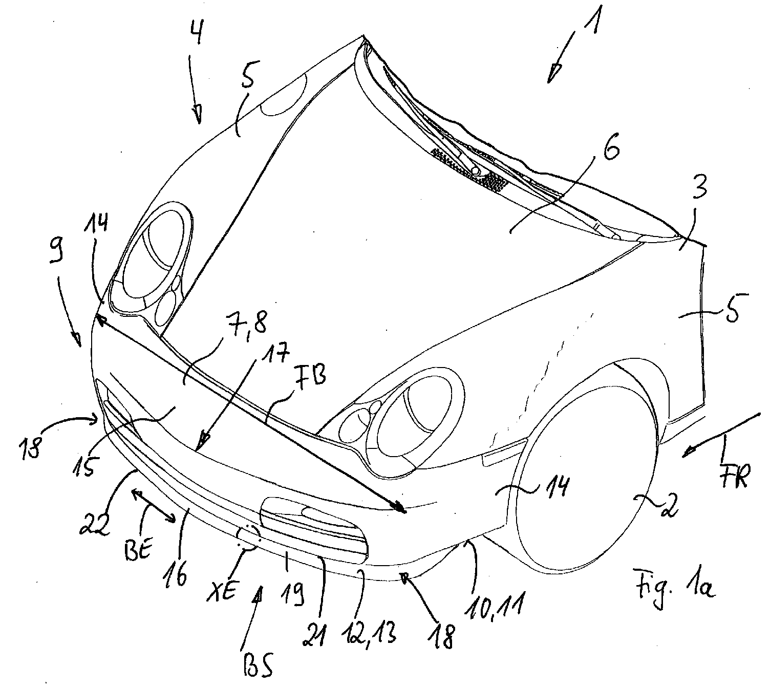
- Fig. 1a shows a detail of a motor vehicle 1, supported by its wheels 2 Structure 3 only a front end 4 can be seen.
- the front section 4 includes parts of Vehicle outer skin forming side fender 5, a hood 6 arranged therebetween and one of the hood 6 and the fenders 5 upstream Bugteil 7, which a Cowling. 8 for a rear bumper (not shown) can represent.
- the front part 7 forms the front end 9 of the motor vehicle first or the front section 4.
- the motor vehicle 1 has a Vehicle width FB, between the lateral longitudinal extensions 14 of the bow part. 7 is measured, which longitudinal extensions 14 on a base 15 of the thus U - shaped Bugteil 7 are connected.
- the louver 12 extends approximately with a strip-shaped spoiler lip 16 over the vehicle width FB and can also - as shown in Fig. 1a - to the be guided lateral longitudinal sections 14. Regardless of whether the spoiler lip 16 extends into the longitudinal sections 14, results for the course of the spoiler lip 16th a contour that follows the rounded contour 17 of the base 15 of the bow part 7. Through her Extension to the longitudinal extensions 14 may be rounded corner regions 18 of Spoiler lip 16 may be provided.
- the louver 12 is in an extended, approximately upright Operating position shown BS, in which the spoiler lip 16 is a downward Extension 19 of the bow portion 7 represents, what else from Figs. 2a and 3 clearer.
- the spoiler lip 16 acts as Aerodynamic air flow guide, which controls the flow of air during the driving of the Motor vehicle 1 depending on desired specifications, such as cheaper Drag coefficient, optimized output forces or the like, influenced.
- the Air guiding device 12 may further from the extended operating position BS in a retracted, rearward and approximately horizontal rest position RS spent be in Figs. 2a and 3 by a dashed line indicated spoiler lip 16th is shown.
- the louver 12 In the rest position RS, the louver 12 substantially no airflow-conducting effect on the motor vehicle 1. From the rest position RS in the extended operating position BS, the spoiler lip 16 via a Actuator 20 shifted, which - seen in the direction of travel FR - behind the Spoiler lip 16 is located and described in more detail below.
- the detail of the spoiler lip 16 marked XE in FIG. 1a is shown in FIG. 1b shown enlarged.
- the spoiler lip 16 is with its upper attachment end 21 with connected to the front part 7 and its lower end forms a free end 22.
- the spoiler lip 16 is made of a fiber composite whose matrix 23 is stretchable and is elastic and in particular of plastic or preferably of an elastomer is made.
- Into the matrix 23 of the fiber composite is internally a first Fiber group 24 embedded, the several approximately parallel to each other extending fibers 25th moreover, transversely, in particular at right angles, to the direction of the vehicle width FB or transverse to the direction of the width extension BE of the spoiler lip 16 aligned are.
- the fibers 25 of the first fiber group 24 are substantially inextensible, the means, when acting on the spoiler lip 16 while driving the motor vehicle 1 Forces or during the movement of the rest position RS in the operating position BS These fibers 25 are not or only a very minor Length change.
- the spoiler lip 16 is replaced by a high stiffness perpendicular to their width extension BE, causing a kinking or excessive bending due of air flow pressure acting in the driving operation of the motor vehicle 1, largely is avoided.
- a material for the fibers 25 of the first fiber group 24 could Polyester, polyamide or aramid can be used.
- a plurality of fibers 26 of a second fiber group 27 can be inserted into the matrix 23 be embedded, which extend in the direction of the width extension BE of the spoiler lip 16, So along the vehicle width FB.
- the fibers 25 the first fiber group 24 and the fibers 26 of the second fiber group 27 approximately oriented at right angles to each other and the fibers 25 extend approximately at right angles to Width extension BE or the fibers 26 extend parallel to the width extension BE the spoiler lip 16.
- the fibers 26 of the second fiber group 27 are made of one stretchable material, especially plastic, made as the rounded contour the bow part 7 following spoiler lip 16 when extending from the rest position RS in the Operating position BS is stretched in the direction of the width extension BE, which is due to the stretchable fibers 26 is insignificant or not hindered. Nevertheless, the reinforce stretchable fibers 26 the fiber composite material.
- the fibers 25 and 26 of the first and second fiber groups 24 and 27 may be referred to as Fabric, knitted or knitted or the like. Be embedded in the matrix 23. alternative For example, the fibers 25 and 26 could be loosely arranged and only through the matrix 23 are fixed in position.
- the fibers 25 of the first fiber group 24 can also be used in multiple layers 28 and 29 ( Figures 2a and 3) and approximately parallel to one another be aligned, wherein the fiber composite material preferably monolayer is made.
- fibers 26 of the second fiber group 27 are the For simplicity's sake not shown. Otherwise, in Figs. 1a to 3 are the same or equivalent parts provided with identical reference numerals.
- Figs. 2a and 3 also shows that at the free end 22 of the spoiler lip 16 is a right angle extending through the plane of the drawing channel 30 in the spoiler lip 16 is formed, which therefore along the width extension BE of the spoiler lip 16th runs.
- this channel 30 is a flexurally elastic and optionally zugelasticians element 31,
- a rod in particular plastic rod KS used.
- Around the channel 30 or the flexurally elastic element 31 is at least one fiber strand 32 with inextensible Fibers, in particular fibers 25 of the first fiber group 24, led around, which Fiber strand 32 in the two layers 28 and 29 of the first fiber group 24 is located.
- This fiber strand 32 extends from an upper mounting portion 33 on Fastening 21 of the spoiler lip 16 down toward the free end 22, is led around there around the channel 30 and can again into the bead-like Attaching portion 33 extend. It would also be conceivable, this fiber strand 32nd in at least one of the layers 28 or 29 at least one predetermined Sollbiegestelle 34 to interrupt, so that in the predetermined bending point 34, the number of Layers 28 and 29 is reduced by one layer. In the region of the predetermined bending point 34 is reduces the stiffness of the spoiler lip 16 so that a deliberate bending take place here can.
- Such a predetermined bending point 34 may be adjacent to the attachment portion 33 and / or be provided at a distance to the flap-like movement of the Rest position RS in the operating position BS of the spoiler lip 16 simplify. These Predetermined bending point 34 may thus form a hinge-like device.
- the fibers 25 of the first range Fiber group 24 only to the free end 22 and to the attachment portion 33rd approach, so end each before.
- the predetermined bending point 34 is formed in a fiber-free region 34 '. Since that flexurally elastic element 31 in the region of the free end 22 for a sufficient Rigidity of the spoiler lip 16 can provide, in particular for manufacturing reasons to bring around the fibers 25 and the fiber strand 32 around the channel 30th be waived.
- the actuator 20 for the spoiler lip 16 is in the embodiments According to FIGS. 2a and 3, in each case, they are designed to be inflatable and emptied and to have them at least one hose 35, which extends along the vehicle width FB or parallel for the width extension BE of the spoiler lip 16 between the bottom 10 and the Rear side 36 of the spoiler lip 16 extends and in the operating position of the spoiler lip 16 -. seen in the direction of travel FR - is behind the spoiler lip 16 and this opposite the Bottom 10 is supported.
- the hose 35 may include one or more chambers 37, 38, 39 have - which are superimposed - and according to FIG. 3 - a substantially oval or have elliptical cross-section, possibly with different cross-sectional size.
- the elliptical cross-section having chambers 37 and 38 with their adjacent ends attached to each other and with their spaced apart ends 40, 41 in the region of the free end 22 of the Spoiler lip 16 or attached to the bottom 10.
- the tube 35 with its at least one chamber 37, 38 or 39 is preferably made of the same material as the matrix and at least includes a stretchable and elastic material, preferably that of the matrix 23.
- the wall 42 of the tube 35 or the chambers 37 to 39 is provided with a fiber reinforcement 43 (FIG. 2b), their fibers 44 are arranged in one or more layers LG and around the circumference UM at least one of the chambers 37 to 39 or to the circumference of the tube 35 in the wall 42 run.
- the fibers 44 are substantially inextensible, whereby a excessive inflation of the corresponding chamber 37, 38 and / or 39 or the Hose is avoided in cross section.
- the fibers 44 of the fiber reinforcement 43 are associated with the non-extensible fibers 25 of the first fiber group 24, and preferably made of the same material.
Landscapes
- Engineering & Computer Science (AREA)
- Chemical & Material Sciences (AREA)
- Combustion & Propulsion (AREA)
- Transportation (AREA)
- Mechanical Engineering (AREA)
- Body Structure For Vehicles (AREA)
- Superstructure Of Vehicle (AREA)
- Laminated Bodies (AREA)
Abstract
Description
- Fi. 1a
- ausschnittweise ein Kraftfahrzeug mit einer Frontpartie und einer Luftleiteinrichtung,
- Fig. 1b
- eine vergrößerte Detaildarstellung der Luftleiteinrichtung nach Fig. 1a,
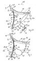
- Fig. 2a
- nach einem ersten Ausführungsbeispiel die Luftleiteinrichtung in Schnittdarstellung,
- Fig. 2b
- eine vergrößerte Detaildarstellung eines Betätigungselements nach Fig. 2a und
- Fig. 3
- die Luftleiteinrichtung nach einem zweiten Ausführungsbeispiel.
Claims (17)
- Luftleiteinrichtung für ein Kraftfahrzeug, mit einem Betätigungselement und einer ganz oder teilweise über die Fahrzeugbreite verlaufenden Spoilerlippe, mit welchem Betätigungselement die Spoilerlippe aus einer eingefahrenen Ruhestellung in eine ausgefahrene Betriebsstellung verlagerbar ist, und welche Spoilerlippe ein elastisches und dehnbares Material umfasst, dadurch gekennzeichnet, dass die Spoilerlippe (16) aus Faserverbundwerkstoff hergestellt ist, dass die Matrix (23) des Faserverbundwerkstoffes dehnbar und elastisch ist, dass eine erste Fasergruppe (24) in die Matrix (23) eingebettete Fasern (25) aufweist, die quer zur Richtung der Fahrzeugbreite (FB), also quer zur Richtung der Breitenerstreckung (BE) der Spoilerlippe (16) verlaufen, und dass die Fasern (25) der ersten Fasergruppe (24) im wesentlichen undehnbar sind.
- Luftleiteinrichtung nach Anspruch 1, dadurch gekennzeichnet, dass in die Matrix (23) eine zweite Fasergruppe (27) eingebettet ist, die Fasern (26) aufweist, die in Richtung der Breitenerstreckung (BE) der Spoilerlippe (16) verlaufen und die elastisch dehnbar sind.
- Luftleiteinrichtung nach Anspruch 1 oder 2, dadurch gekennzeichnet, dass die Fasern (25, 26) der ersten und/oder zweiten Fasergruppe (24, 27) als Gewebe oder Gestrick oder Gewirk in die Matrix (23) eingebettet sind.
- Luftleiteinrichtung nach Anspruch 1, dadurch gekennzeichnet, dass der Faserverbundwerkstoff einschichtig ausgeführt ist.
- Luftleiteinrichtung nach Anspruch 1, dadurch gekennzeichnet, dass an einem freien Ende (22) innerhalb der Spoilerlippe (16) ein sich entlang der Fahrzeugbreite (FB) erstreckendes zumindest biegeelastisches Element (31) angeordnet ist.
- Luftleiteinrichtung nach Anspruch 5, dadurch gekennzeichnet, dass zumindest einige Fasern (25) der ersten Fasergruppe (24) um das biegeelastische Element (31) zumindest teilweise herumgeführt sind.
- Luftleiteinrichtung nach Anspruch 1 oder 6, dadurch gekennzeichnet, dass die erste Fasergruppe mehrere Faserlagen (28, 29) aufweist, und dass zumindest ein Faserstrang (32) in zwei Faserlagen (28, 29) verläuft.
- Luftleiteinrichtung nach Anspruch 7, dadurch gekennzeichnet, dass der Faserstrang (32) um das biegeelastische Element (31) herumgeführt ist.
- Luftleiteinrichtung nach Anspruch 5, dadurch gekennzeichnet, dass die Fasern (25) der ersten Fasergruppe (24) bis an das biegeelastische Element (31) herangeführt sind.
- Luftleiteinrichtung nach Anspruch 1 oder 2, dadurch gekennzeichnet, dass die Fasern (25, 26) der ersten und/oder zweiten Fasergruppe (24, 27) eine oder mehrere Faserlagen (28, 29) aufweisen.
- Luftteiteinrichtung nach vorhergehenden Anspruch 10, dadurch gekennzeichnet, dass die erste Fasergruppe (24) mit den mehreren Faserlagen (28, 29) in einem Sollbiegebereich (34) der Spoilerlippe (16) um zumindest eine Lage (28, 29) reduziert sind.
- Luftleiteinrichtung nach Anspruch 1, dadurch gekennzeichnet, dass das Betätigungselement (20) für die Spoilerlippe (16) ein sich entlang der Fahrzeugbreite (FB) wenigstens abschnittweise erstreckender Schlauch (35) mit zumindest einer aufblasbaren Kammer (37, 38, 39) ist und dass der Schlauch (35) aus dehnbarem und elastischem Material, vorzugsweise dem der Matrix (23), hergestellt ist.
- Luftleiteinrichtung nach Anspruch 12, dadurch gekennzeichnet, dass eine Wand (42) des Schlauchs bzw. einer Kammer (37, 38, 39) mit einer Faserverstärkung (43) versehen ist.
- Luftleiteinrichtung nach Anspruch 13, dadurch gekennzeichnet, dass die Faserverstärkung (43) in der Wand (42) im wesentlichen undehnbare Fasern (44) aufweist, die zumindest teilweise um den Umfang (UM) der Kammer (37, 38, 39) herumgeführt und der ersten Fasergruppe (24) zugeordnet sind.
- Luftleiteinrichtung nach Anspruch 1, dadurch gekennzeichnet, dass die Spoilerlippe (16) einen Befestigungsabschnitt (33) aufweist, mit dem sie mit dem Kraftfahrzeug (1) verbindbar ist.
- Luftleiteinrichtung nach Anspruch 11 und 15, dadurch gekennzeichnet, dass die Fasern (25) der ersten Fasergruppe (24) bis in den Befestigungsabschnitt (33) gelegt sind und dass benachbart zum Befestigungsabschnitt (33) der Sollbiegebereich (34) ausgebildet ist.
- Luftleiteinrichtung nach Anspruch 15, dadurch gekennzeichnet, dass die Fasern (25) der ersten Fasergruppe (24) vor dem Befestigungsabschnitt (33) enden.
Applications Claiming Priority (2)
| Application Number | Priority Date | Filing Date | Title |
|---|---|---|---|
| DE10325653A DE10325653A1 (de) | 2003-06-06 | 2003-06-06 | Luftleiteinrichtung für ein Kraftfahrzeug |
| DE10325653 | 2003-06-06 |
Publications (3)
| Publication Number | Publication Date |
|---|---|
| EP1484238A2 true EP1484238A2 (de) | 2004-12-08 |
| EP1484238A3 EP1484238A3 (de) | 2005-08-10 |
| EP1484238B1 EP1484238B1 (de) | 2008-01-09 |
Family
ID=33154572
Family Applications (1)
| Application Number | Title | Priority Date | Filing Date |
|---|---|---|---|
| EP04008582A Expired - Lifetime EP1484238B1 (de) | 2003-06-06 | 2004-04-08 | Luftleiteinrichtung für ein Kraftfahrzeug |
Country Status (3)
| Country | Link |
|---|---|
| US (1) | US7055891B2 (de) |
| EP (1) | EP1484238B1 (de) |
| DE (2) | DE10325653A1 (de) |
Cited By (1)
| Publication number | Priority date | Publication date | Assignee | Title |
|---|---|---|---|---|
| FR2983451A1 (fr) * | 2011-12-05 | 2013-06-07 | Peugeot Citroen Automobiles Sa | Jupe pliable de bas de longeron de chassis ou de bas de pare-chocs ameliorant l'aerodynamisme d'un vehicule |
Families Citing this family (30)
| Publication number | Priority date | Publication date | Assignee | Title |
|---|---|---|---|---|
| WO2006115988A2 (en) * | 2005-04-21 | 2006-11-02 | Roderick Dayton | Vehicle air dam system |
| JP4301287B2 (ja) * | 2005-12-27 | 2009-07-22 | トヨタ自動車株式会社 | 車両用スパッツ装置 |
| NL2000328C2 (nl) * | 2006-11-23 | 2008-05-26 | Vredestein Banden B V | Werkwijze voor het onderling hechten van vormdelen uit gevulkaniseerd rubber. |
| NL2000330C2 (nl) * | 2006-11-23 | 2008-05-26 | Vredestein Banden B V | Polymeersamenstelling. |
| NL2000329C2 (nl) * | 2006-11-23 | 2008-05-26 | Porsche Ag | Werkwijze voor het vervaardigen van een vormdeel met inzetstuk uit een rubberpolymeer. |
| NL2000505C2 (nl) * | 2007-02-23 | 2008-08-26 | Vredestein Banden B V | Werkwijze voor het onderling hechten van vormdelen uit gevulkaniseerd rubber en uit kunststof. |
| CA2642163C (en) * | 2008-11-12 | 2010-08-17 | Roderick M. Dayton | System for reducing aerodynamic drag on vehicles |
| US7866734B2 (en) * | 2009-03-13 | 2011-01-11 | Mracek Milo F | Inflatable shaping system reducing the aerodynamic drag upon the rear of a vehicle |
| US8292350B2 (en) | 2010-04-26 | 2012-10-23 | GM Global Technology Operations LLC | Inflatable vehicle air dam with bidirectional deploy/stow system |
| DE102010021187B4 (de) | 2010-05-21 | 2021-12-30 | Apollo Vredestein B.V. | Frontspoiler eines Kraftfahrzeugs |
| DE102011111456B4 (de) * | 2011-08-30 | 2022-05-05 | Apollo Vredestein B.V. | Luftleiteinrichtung für ein Kraftfahrzeug |
| US9132869B2 (en) | 2011-11-10 | 2015-09-15 | Roderick M Dayton | Aerodynamic drag reduction system |
| DE102012020739B4 (de) | 2012-10-23 | 2022-03-03 | Apollo Vredestein B.V. | Luftleiteinrichtung eines Kraftfahrzeugs |
| NL2009835C2 (en) | 2012-11-19 | 2014-05-21 | Apollo Vredestein Bv | Method for manufacturing a molded article of a rubber polymer to which another article is detachably connected. |
| NL2009869C2 (en) | 2012-11-23 | 2014-05-27 | Apollo Vredestein Bv | Polymer composition and moulded articles thereof. |
| NL2009868C2 (en) | 2012-11-23 | 2014-05-27 | Apollo Vredestein Bv | Method of manufacturing an elastomeric product with a low hysteresis. |
| NL2011122C2 (en) | 2013-07-09 | 2015-01-12 | Apollo Vredestein Bv | Method for manufacturing a molded article with insert from a rubber polymer. |
| NL2012011C2 (en) * | 2013-12-20 | 2015-06-26 | Apollo Vredestein Bv | Vehicle front spoiler. |
| DE102014104156A1 (de) | 2014-03-26 | 2015-10-01 | Dr. Ing. H.C. F. Porsche Aktiengesellschaft | Luftleiteinrichtung für ein Kraftfahrzeug |
| US9399493B1 (en) * | 2015-03-23 | 2016-07-26 | Karl F. Milde, Jr. | Windshield air deflector for a motor vehicle |
| GB2539984B (en) * | 2015-09-24 | 2017-05-17 | Ford Global Tech Llc | Deployable pedestrian safety device with membrane for vehicles |
| DE102015223771A1 (de) * | 2015-11-30 | 2017-06-01 | Röchling Automotive SE & Co. KG | Rad-Staulippe mit Schall absorbierendem Material |
| JP2017202751A (ja) * | 2016-05-12 | 2017-11-16 | トヨタ自動車株式会社 | 2方向切換えリブによる車両空力特性最適化装置 |
| FR3061124A1 (fr) * | 2016-12-22 | 2018-06-29 | Compagnie Plastic Omnium | Systeme aerodynamique retractable pour vehicule automobile. |
| DE102018108810B4 (de) * | 2018-04-13 | 2022-05-12 | Dr. Ing. H.C. F. Porsche Aktiengesellschaft | Luftleitanordnung für ein Kraftfahrzeug |
| US10589804B2 (en) * | 2018-05-02 | 2020-03-17 | GM Global Technology Operations LLC | Rear diffuser system for an automotive vehicle |
| DE102018216007A1 (de) * | 2018-09-20 | 2020-03-26 | Bayerische Motoren Werke Aktiengesellschaft | Spoilerlippe zur Anordnung an einer Frontpartie eines Kraftfahrzeugs und Kraftfahrzeug |
| DE102019135533A1 (de) * | 2019-12-20 | 2021-06-24 | Apollo Tyres Global R&D B.V. | Luftstrom-Führungselement |
| CN113562085B (zh) * | 2021-08-09 | 2022-11-01 | 华侨大学 | 一种方程式赛车改善前轮绕流的前翼结构 |
| US12078003B2 (en) * | 2021-09-29 | 2024-09-03 | Honda Motor Co., Ltd. | Active front structure for vehicle |
Family Cites Families (4)
| Publication number | Priority date | Publication date | Assignee | Title |
|---|---|---|---|---|
| IT1153678B (it) * | 1982-12-10 | 1987-01-14 | Alfa Romeo Spa | Spoiler a posizionamento automatico per un autoveicolo |
| CN1308178C (zh) * | 2000-12-23 | 2007-04-04 | 宝马公司 | 汽车车身外壳的平坦部分 |
| DE10160748B8 (de) * | 2001-12-11 | 2005-09-29 | Dr.Ing.H.C. F. Porsche Ag | Kraftfahrzeug mit einer eine Luftleiteinrichtung umfassenden Frontpartie |
| DE10325654A1 (de) * | 2003-06-06 | 2004-12-23 | Dr.Ing.H.C. F. Porsche Ag | Luftleiteinrichtung für ein Kraftfahrzeug |
-
2003
- 2003-06-06 DE DE10325653A patent/DE10325653A1/de not_active Withdrawn
-
2004
- 2004-04-08 DE DE502004005884T patent/DE502004005884D1/de not_active Expired - Lifetime
- 2004-04-08 EP EP04008582A patent/EP1484238B1/de not_active Expired - Lifetime
- 2004-06-07 US US10/861,908 patent/US7055891B2/en not_active Expired - Lifetime
Cited By (1)
| Publication number | Priority date | Publication date | Assignee | Title |
|---|---|---|---|---|
| FR2983451A1 (fr) * | 2011-12-05 | 2013-06-07 | Peugeot Citroen Automobiles Sa | Jupe pliable de bas de longeron de chassis ou de bas de pare-chocs ameliorant l'aerodynamisme d'un vehicule |
Also Published As
| Publication number | Publication date |
|---|---|
| US7055891B2 (en) | 2006-06-06 |
| DE502004005884D1 (de) | 2008-02-21 |
| US20050017541A1 (en) | 2005-01-27 |
| EP1484238B1 (de) | 2008-01-09 |
| EP1484238A3 (de) | 2005-08-10 |
| DE10325653A1 (de) | 2004-12-23 |
Similar Documents
| Publication | Publication Date | Title |
|---|---|---|
| EP1484238B1 (de) | Luftleiteinrichtung für ein Kraftfahrzeug | |
| EP1319585B1 (de) | Kraftfahrzeug mit einer eine Luftleiteinrichtung umfassenden Frontpartie | |
| EP2983934B1 (de) | Luftführung | |
| DE3617538C2 (de) | ||
| EP2754571B1 (de) | Balg eines Übergangs eines Gelenkfahrzeugs sowie Gelenkfahrzeug des öffentlichen Personentransports mit einem solchen Balg | |
| DE102004030571A1 (de) | Luftleitvorrichtung für ein Kraftfahrzeug | |
| EP2011723A2 (de) | Luftleiteinrichtung eines Kraftfahrzeuges | |
| DE102011085933B4 (de) | Unterbodenverkleidung für ein Kraftfahrzeug mit beweglichen Teilen | |
| EP1410954B1 (de) | Stossfänger für ein Kraftfahrzeug | |
| EP4143076A1 (de) | Luftleiteinrichtung für einen personenkraftwagen sowie personenkraftwagen | |
| EP1484237B1 (de) | Luftleiteinrichtung für ein Kraftfahrzeug | |
| DE102014111074A1 (de) | Luftströmungsleitvorrichtung für Kraftfahrzeuge | |
| DE10162758B4 (de) | Windschott für ein Cabriolet | |
| DE102011121909A1 (de) | Karosserieelement | |
| DE10325652B4 (de) | Verfahren zur Herstellung einer Spoilerlippe einer Luftleiteinrichtung für ein Kraftfahrzeug | |
| DE102016010321A1 (de) | Spoileranordnung für ein Kraftfahrzeug | |
| DE102019102641A1 (de) | Anordnung eines Schmutzfängers an einem Radkasten eines Kraftfahrzeugs sowie Kraftfahrzeug | |
| DE2646663B2 (de) | Faltenbalg für Gelenkfahrzeuge | |
| DE102020103605A1 (de) | Aufblasbares Fahrzeugkarosserieelement | |
| EP4196385B1 (de) | Unterbodenverkleidungselement für ein fahrzeug sowie anordnung einer unterbodenverkleidung an einem aufbau eines fahrzeugs | |
| DE102015207326B4 (de) | Spoilerlippe für ein Kraftfahrzeug | |
| EP4247669B1 (de) | Aussenverkleidung für einen kraftwagen | |
| DE3330397C2 (de) | ||
| DE102011112245A1 (de) | Längsträgerverkleidung für ein Kraftfahrzeug | |
| DE4001447C1 (en) | Conduction air flow arrangement for vehicle - in in front of heat exchanger and diffuser lengths of connecting shafts enlarge with distance from ram air flow impact point |
Legal Events
| Date | Code | Title | Description |
|---|---|---|---|
| PUAI | Public reference made under article 153(3) epc to a published international application that has entered the european phase |
Free format text: ORIGINAL CODE: 0009012 |
|
| AK | Designated contracting states |
Kind code of ref document: A2 Designated state(s): AT BE BG CH CY CZ DE DK EE ES FI FR GB GR HU IE IT LI LU MC NL PL PT RO SE SI SK TR |
|
| AX | Request for extension of the european patent |
Extension state: AL HR LT LV MK |
|
| PUAL | Search report despatched |
Free format text: ORIGINAL CODE: 0009013 |
|
| AK | Designated contracting states |
Kind code of ref document: A3 Designated state(s): AT BE BG CH CY CZ DE DK EE ES FI FR GB GR HU IE IT LI LU MC NL PL PT RO SE SI SK TR |
|
| AX | Request for extension of the european patent |
Extension state: AL HR LT LV MK |
|
| 17P | Request for examination filed |
Effective date: 20060210 |
|
| AKX | Designation fees paid |
Designated state(s): DE FR GB IT NL |
|
| 17Q | First examination report despatched |
Effective date: 20061218 |
|
| GRAP | Despatch of communication of intention to grant a patent |
Free format text: ORIGINAL CODE: EPIDOSNIGR1 |
|
| GRAS | Grant fee paid |
Free format text: ORIGINAL CODE: EPIDOSNIGR3 |
|
| GRAA | (expected) grant |
Free format text: ORIGINAL CODE: 0009210 |
|
| AK | Designated contracting states |
Kind code of ref document: B1 Designated state(s): DE FR GB IT NL |
|
| REG | Reference to a national code |
Ref country code: GB Ref legal event code: FG4D Free format text: NOT ENGLISH |
|
| REF | Corresponds to: |
Ref document number: 502004005884 Country of ref document: DE Date of ref document: 20080221 Kind code of ref document: P |
|
| GBT | Gb: translation of ep patent filed (gb section 77(6)(a)/1977) |
Effective date: 20080414 |
|
| RAP2 | Party data changed (patent owner data changed or rights of a patent transferred) |
Owner name: DR. ING. H.C. F. PORSCHE AKTIENGESELLSCHAFT |
|
| NLT2 | Nl: modifications (of names), taken from the european patent patent bulletin |
Owner name: DR. ING. H.C. F. PORSCHE AKTIENGESELLSCHAFT Effective date: 20080514 |
|
| RAP2 | Party data changed (patent owner data changed or rights of a patent transferred) |
Owner name: DR. ING. H.C. F. PORSCHE AKTIENGESELLSCHAFT |
|
| ET | Fr: translation filed | ||
| NLT2 | Nl: modifications (of names), taken from the european patent patent bulletin |
Owner name: DR. ING. H.C. F. PORSCHE Effective date: 20080716 |
|
| PLBE | No opposition filed within time limit |
Free format text: ORIGINAL CODE: 0009261 |
|
| STAA | Information on the status of an ep patent application or granted ep patent |
Free format text: STATUS: NO OPPOSITION FILED WITHIN TIME LIMIT |
|
| 26N | No opposition filed |
Effective date: 20081010 |
|
| REG | Reference to a national code |
Ref country code: FR Ref legal event code: TP |
|
| REG | Reference to a national code |
Ref country code: FR Ref legal event code: CD |
|
| REG | Reference to a national code |
Ref country code: FR Ref legal event code: TP |
|
| REG | Reference to a national code |
Ref country code: GB Ref legal event code: 732E Free format text: REGISTERED BETWEEN 20110310 AND 20110316 |
|
| REG | Reference to a national code |
Ref country code: GB Ref legal event code: 732E Free format text: REGISTERED BETWEEN 20110331 AND 20110406 |
|
| REG | Reference to a national code |
Ref country code: FR Ref legal event code: PLFP Year of fee payment: 13 |
|
| PGFP | Annual fee paid to national office [announced via postgrant information from national office to epo] |
Ref country code: NL Payment date: 20160420 Year of fee payment: 13 |
|
| REG | Reference to a national code |
Ref country code: FR Ref legal event code: PLFP Year of fee payment: 14 |
|
| PGFP | Annual fee paid to national office [announced via postgrant information from national office to epo] |
Ref country code: IT Payment date: 20170424 Year of fee payment: 14 |
|
| REG | Reference to a national code |
Ref country code: NL Ref legal event code: MM Effective date: 20170501 |
|
| PG25 | Lapsed in a contracting state [announced via postgrant information from national office to epo] |
Ref country code: NL Free format text: LAPSE BECAUSE OF NON-PAYMENT OF DUE FEES Effective date: 20170501 |
|
| REG | Reference to a national code |
Ref country code: FR Ref legal event code: PLFP Year of fee payment: 15 |
|
| PG25 | Lapsed in a contracting state [announced via postgrant information from national office to epo] |
Ref country code: IT Free format text: LAPSE BECAUSE OF NON-PAYMENT OF DUE FEES Effective date: 20180408 |
|
| PGFP | Annual fee paid to national office [announced via postgrant information from national office to epo] |
Ref country code: GB Payment date: 20220420 Year of fee payment: 19 Ref country code: FR Payment date: 20220420 Year of fee payment: 19 |
|
| PGFP | Annual fee paid to national office [announced via postgrant information from national office to epo] |
Ref country code: DE Payment date: 20230419 Year of fee payment: 20 |
|
| GBPC | Gb: european patent ceased through non-payment of renewal fee |
Effective date: 20230408 |
|
| PG25 | Lapsed in a contracting state [announced via postgrant information from national office to epo] |
Ref country code: GB Free format text: LAPSE BECAUSE OF NON-PAYMENT OF DUE FEES Effective date: 20230408 |
|
| PG25 | Lapsed in a contracting state [announced via postgrant information from national office to epo] |
Ref country code: GB Free format text: LAPSE BECAUSE OF NON-PAYMENT OF DUE FEES Effective date: 20230408 Ref country code: FR Free format text: LAPSE BECAUSE OF NON-PAYMENT OF DUE FEES Effective date: 20230430 |
|
| REG | Reference to a national code |
Ref country code: DE Ref legal event code: R071 Ref document number: 502004005884 Country of ref document: DE |