EP1483512B1 - Attache - Google Patents
Attache Download PDFInfo
- Publication number
- EP1483512B1 EP1483512B1 EP03704030A EP03704030A EP1483512B1 EP 1483512 B1 EP1483512 B1 EP 1483512B1 EP 03704030 A EP03704030 A EP 03704030A EP 03704030 A EP03704030 A EP 03704030A EP 1483512 B1 EP1483512 B1 EP 1483512B1
- Authority
- EP
- European Patent Office
- Prior art keywords
- bushing
- shank
- diameter
- section
- pin
- Prior art date
- Legal status (The legal status is an assumption and is not a legal conclusion. Google has not performed a legal analysis and makes no representation as to the accuracy of the status listed.)
- Expired - Fee Related
Links
- 238000003780 insertion Methods 0.000 claims description 13
- 230000037431 insertion Effects 0.000 claims description 13
- 230000007774 longterm Effects 0.000 description 6
- 230000008439 repair process Effects 0.000 description 4
- 230000002411 adverse Effects 0.000 description 3
- 230000000694 effects Effects 0.000 description 2
- 230000015572 biosynthetic process Effects 0.000 description 1
- 238000010276 construction Methods 0.000 description 1
- 238000000034 method Methods 0.000 description 1
- 230000003014 reinforcing effect Effects 0.000 description 1
- 230000000717 retained effect Effects 0.000 description 1
Images


Classifications
-
- F—MECHANICAL ENGINEERING; LIGHTING; HEATING; WEAPONS; BLASTING
- F16—ENGINEERING ELEMENTS AND UNITS; GENERAL MEASURES FOR PRODUCING AND MAINTAINING EFFECTIVE FUNCTIONING OF MACHINES OR INSTALLATIONS; THERMAL INSULATION IN GENERAL
- F16B—DEVICES FOR FASTENING OR SECURING CONSTRUCTIONAL ELEMENTS OR MACHINE PARTS TOGETHER, e.g. NAILS, BOLTS, CIRCLIPS, CLAMPS, CLIPS OR WEDGES; JOINTS OR JOINTING
- F16B5/00—Joining sheets or plates, e.g. panels, to one another or to strips or bars parallel to them
- F16B5/06—Joining sheets or plates, e.g. panels, to one another or to strips or bars parallel to them by means of clamps or clips
- F16B5/0607—Joining sheets or plates, e.g. panels, to one another or to strips or bars parallel to them by means of clamps or clips joining sheets or plates to each other
- F16B5/0621—Joining sheets or plates, e.g. panels, to one another or to strips or bars parallel to them by means of clamps or clips joining sheets or plates to each other in parallel relationship
- F16B5/0642—Joining sheets or plates, e.g. panels, to one another or to strips or bars parallel to them by means of clamps or clips joining sheets or plates to each other in parallel relationship the plates being arranged one on top of the other and in full close contact with each other
-
- F—MECHANICAL ENGINEERING; LIGHTING; HEATING; WEAPONS; BLASTING
- F16—ENGINEERING ELEMENTS AND UNITS; GENERAL MEASURES FOR PRODUCING AND MAINTAINING EFFECTIVE FUNCTIONING OF MACHINES OR INSTALLATIONS; THERMAL INSULATION IN GENERAL
- F16B—DEVICES FOR FASTENING OR SECURING CONSTRUCTIONAL ELEMENTS OR MACHINE PARTS TOGETHER, e.g. NAILS, BOLTS, CIRCLIPS, CLAMPS, CLIPS OR WEDGES; JOINTS OR JOINTING
- F16B19/00—Bolts without screw-thread; Pins, including deformable elements; Rivets
- F16B19/04—Rivets; Spigots or the like fastened by riveting
- F16B19/08—Hollow rivets; Multi-part rivets
- F16B19/10—Hollow rivets; Multi-part rivets fastened by expanding mechanically
- F16B19/1027—Multi-part rivets
- F16B19/1036—Blind rivets
- F16B19/1081—Blind rivets fastened by a drive-pin
Definitions
- the present invention relates to a clip comprising a bushing with a hollow flange and shank, and a pin with a shank for insertion into the bushing, in which the bushing shank is inserted into holes in workpieces such as a plurality of panels, and in which the pin shank is inserted from the bushing flange end into the hollow shank of the bushing, the diameter of the bushing shank is expanded, and the plurality of workpieces are joined together by the expanded-diameter bushing shank section and the bushing flange.
- Clips well known in the art comprise a bushing with a hollow flange and shank, and a pin with a shank for insertion into the bushing, in which the bushing shank is inserted into holes in workpieces such as a plurality of panels, and in which the pin shank is inserted from the bushing flange end into the hollow shank of the bushing, the diameter of the bushing shank is expanded, and the plurality of workpieces are joined together by the expanded-diameter bushing shank section and the bushing flange.
- US-A-5 641 255 Japanese Unexamined Patent Application Disclosure [Kokai] No. 08-004733
- US-A-6 039 523 This clip has a plastic bushing with a hollow flange and shank, and a plastic pin with a shank for insertion into the bushing.
- the bushing shank is inserted into holes in workpieces such as a plurality of panels, the pin shank is inserted from the bushing flange end into the hollow shank of the bushing, the diameter of the bushing shank is expanded, and the plurality of workpieces are joined together by the expanded-diameter bushing shank section and the bushing flange.
- these well known plastic clips consisting of a pin and bushing hold workpieces together when the pin shank is inserted into the bushing shank and the diameter of the end of the bushing shank is expanded.
- the expanded-diameter section of the bushing shank remains deformed with an expanded diameter (although there is some narrowing) due to a form of deformation over the years called "creep deformation".
- the creep deformation makes it more difficult to insert the large-diameter deformed bushing shank into the holes in the workpieces than inserting a bushing shank without any large-diameter deformation.
- the clip may not be inserted properly, the bushing shank may be damaged, or the attachment holes in the workpieces may be damaged.
- a clip was disclosed in US-A-5 641 255 in which creep deformation is countered by forming a plurality of notches in the bushing shank and by forming a hole in the end of the pin shank for receiving the end of the bushing shank.
- the pin shank is removed from the bushing shank after being connected for a long time, the end of the bushing shank is received by the hole in the end of the pin shank, the diameter of the large-diameter section of the bushing shank is removed from the pin shank and narrowed, and the clip is easily removed. This counters the creep deformation in the bushing shank.
- the formation of a hole in the end of the pin shank for receiving the bushing shank means the pin shank has a complicated shape.
- the purpose of the present invention is to provide a clip that can be re-used even when the clip has a creep-deformed bushing shank despite having a pin shank with a simple shape, and having a bushing shank that can be expanded outward radially without requiring the application of excessive force.
- a clip comprising a bushing with a hollow flange and shank, and a pin with a shank for insertion into the bushing, wherein the bushing shank is inserted into holes in workpieces such as a plurality of panels, wherein the pin shank is inserted from the bushing flange end into the hollow shank of the bushing, the diameter of the bushing shank is expanded and the plurality of workpieces are joined together by the expanded-diameter bushing shank section and the bushing flange, wherein a guide is formed in the end of the pin shank extending from the end of the bushing shank in a position where the diameter of the bushing shank does not expand with the pin shank inserted into the bushing shank, wherein the guide has a large-diameter section with a diameter larger than the end of the bushing shank, and wherein the diameter of the large-diameter section is greater than the diameter of a creep-deformed bushing sh
- the guide at the end of the pin shank inserted into the bushing shank has a larger diameter than the end of a creep-deformed bushing shank, the guide has the effect of leading it through the holes in the workpieces.
- a bushing shank without large-diameter deformation it does not catch in the attachment holes and attachment can be performed easily without taking any special precautions.
- the insertion is performed properly, the bushing shank is not damaged, and the attachment holes in the workpieces are not damaged.
- the large-diameter section at the end of the bushing shank is finely tapered or arrow-shaped towards the end.
- a thick section is formed in the end of the bushing shank extending into the hollow section of the bushing shank so the diameter of the bushing shank can be greatly expanded by the insertion of the pin shank, and a thin section is formed in the end of the pin shank so as to receive the section near the large-diameter section so the diameter of the thick section is not expanded.
- An elastic locking tab extending towards the hollow section of the bushing is formed in the bushing shank near the bushing flange section or bushing flange, and a catching groove is formed in the pin shank for catching the locking tab when the diameter of the bushing shank is not expanded.
- the pin and bushing are temporarily connected so the diameter of the bushing shank is not expanded when the locking tab engages the catching groove, and the bushing shank is prevented from riding over the large-diameter section of the pin shank and coming loose.
- a receiving groove is formed in the pin shank so as to receive the locking tab on the bushing shank without deformation when the pin shank has been inserted into the bushing shank and the diameter of the end of the bushing shank has been expanded.
- the bushing shank is also equipped with legs divided into pluralities circumferentially and extending axially.
- the section of the legs from the base section near the bushing flange to the section near the end is thinner than the section at the end, and a slit longer than the thickness of the workpieces is formed in the thin section of the legs extending axially.
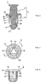
- Fig. 1 is a planar view of the non-expanded connecting section of the clip in a working example of the present invention.
- Fig 2 is a cross-sectional view of the clip in Fig. 1 along line A-A.
- Fig. 3 is a cross-sectional view of the clip in Fig. 2 along line B-B.
- Fig. 4 is a planar view of the bushing.
- Fig. 5 is a frontal view of the bushing.
- Fig. 6 is a bottom view of the bushing.
- Fig. 7 is a cross-sectional view of a section of the bushing in Fig. 4 along line C-C.
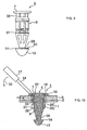
- Fig. 8 is a planar view of the pin.
- Fig. 9 is a frontal view of the pin.
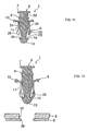
- Fig. 10 is a cross-sectional view similar to Fig. 3 showing a clip that is to be removed connected to a workpiece.
- Fig. 11 is a cross-sectional view similar to Fig. 3 showing the clip removed from the workpiece.
- Fig. 12 is a cross-sectional view similar to Fig. 3 showing the reused clip prior to being connected to a workpiece.
- Fig. 1 through Fig. 9 show the clip 1 in the first working example of the present invention.
- the clip 1 is equipped with a pin 5 and a bushing 6 as shown in Fig. 1 through Fig. 3 .
- Fig. 4 through Fig. 7 shows the configuration of the bushing 6 in greater detail.
- Fig. 8 and Fig. 9 show the configuration of the pin 5 in greater detail.
- the attached clip 1 is removed from the workpieces 2, 3 in order to repair or replace the workpieces.
- workpiece 2 is a car body and workpiece 3 is a component attached to the car body.
- Fig. 11 shows a clip 1 removed after long-term use.
- Fig. 12 shows the reused clip 1 in Fig. 11 before being inserted into the workpieces 2, 3.
- the clip 1 has two components: a pin 5 and a bushing 6.
- the pin 5 and the bushing 6 are made of plastic and integrated with each other.
- the pin 5 has a round, large-diameter head 7 and a shank 9 beneath the head 7 as shown in Fig. 1 through Fig. 3 and Fig. 8 through Fig. 9 .
- the bushing 6 has a round flange 10 and a shank 11 beneath the flange 10 as shown in Fig. 1 through Fig. 2 and Fig. 4 through Fig. 9 .
- the bushing is hollow so as to receive the pin shank 9.
- the bushing shank 11 When workpieces 2, 3 such as panels are connected, the bushing shank 11 is inserted into the holes in the workpieces 2, 3, the pin shank 9 is inserted into the hollow section of the bushing shank 11 from the end with the bushing flange 10, the diameter of the end of the bushing shank 11 is expanded, and the end of the bushing shank 11 with the expanded diameter and the bushing flange 10 connect the workpieces 2, 3 to each other.
- the connection is shown in Fig. 10 .
- the clip 1 As shown in Fig. 1 through Fig. 3 , the clip 1 is connected so the pin 5 and bushing 6 do not come apart and are assembled so there is a connection without an expanded diameter.
- the clip with the pin 5 connected to the bushing 6 is provided to the user, so the time-consuming assembly of the pin and bushing is eliminated.
- a connection without an expanded diameter occurs when the bushing shank connecting the panels in Fig. 10 is removed.
- a connection without an expanded diameter also occurs when the clip is reused in Fig. 12 .
- a guide 13 is formed in the end of the pin shank 9 extending from the end of the bushing shank 11 in a position where the diameter of the bushing shank 11 does not expand with the pin shank inserted into the bushing shank 11.
- the guide 13 has a large-diameter section 14 with a diameter larger than the end of the bushing shank 11, and the diameter of the large-diameter section 14 is greater than the diameter of the creep-deformed bushing shank 11 section when the diameter is expanded by the pin shank 9.
- Fig. 8 and Fig. 9 show the configuration of the pin 5 in greater detail.
- Fig. 4 through Fig. 7 show the configuration of the bushing 6 in greater detail.
- the bushing flange 10 is a round plate with a diameter greater than the pin head 7.
- a round groove 15 is formed in the top to receive the pin head 7.
- the diameter of the groove 15 is somewhat larger than the pin head 7.
- a gap 18 ( FIG 10 ) is formed to insert the tip of a tool 17 such as a screw driver between the outer edge of the pin head 7 and the inner edge of the groove 15.
- a hole 19 is formed in the center of the bushing flange to accommodate the pin shank.
- the through-hole 19 passes through the bushing shank 11 to accommodate the pin shank 9.
- Three ribs 21 for reinforcing the flange extend radially at equal angles on the bottom surface of the bushing flange 10. Locking tabs 22 extend elastically from the ribs 21 towards the through-hole 19.
- the locking tabs 22 can be formed radially from the section of the bushing shank 11 near the bushing flange 10 so as not to adversely affect the expanding diameter of the bushing flange 11.
- the elastic locking tabs 22 also extend radially inward towards the end of the bushing shank.
- a catching groove (explained below) formed in the pin shank 9 is engaged to temporarily connect the pin 5 and bushing 6 when the diameter is not expanded. The bushing shank 11 is thus prevented from riding over the large-diameter section 14 of the guide 13 in the pin shank 9 and coming loose.
- the bushing shank 11 is divided into a plurality of legs 23 (three in this working example) extending circumferentially and axially.
- the ribs 21 and elastic locking tabs 22 are positioned in the gap between the two closer legs 23 as shown in Fig. 6 so as not to adversely affect the expanding diameter of the bushing legs 23.
- the elastic thin section 25 of the legs 23 from the base section near the bushing flange 10 to the section near the end is thinner than the thick section 26 from the thin section 25 to the end.
- the elasticity is such that the legs 23 bend sufficiently to the outside.
- the diameter of the bushing shank 11 does not expand.
- the thin section 25 is flexible enough to be expanded greatly by the thick section 26 when the pin shank 9 is inserted but rigid enough not to become deformed even when expanded greatly.
- the radial thickness of the thick section 26 has to be such that the insertion of the pin shank 9 into the bushing shank 11 expands the diameter of the thick section 26, moves with the bushing flange 10, and connects the workpieces 2, 3.
- a slit 27 is formed extending axially from the base section of the bushing shank 11 (the section near the bushing flange 10) in the legs 23 to just before the thick section 26.
- the pin 5 is longer than the bushing 6 (twice as long in the working example shown in the figures) so the pin remains inserted in through-hole of the bushing 6.
- a non-expanded connection is shown in FIG 1 through FIG 3 and an expanded connection is shown in Fig. 10 .
- Fig. 11 and Fig. 12 show the non-expanded connection when the pin 5 is removed from a bushing 6 with an expanded connection and reused.
- the pin head 7 is a round plate, but the edge cuts inward on a slope so as not to be angular from top to bottom. This forms a gap between the top and bottom of the flange into which a tool such as a screw driver can be inserted.
- the diameter of the pin head 7 should be large enough to keep from coming out of the through-hole 19 in the bushing flange 10.
- the pin shank 9 is barrel-shaped and extends downward from the head 7.
- a guide 13 is formed in the end (the bottom end in Fig. 9 ).
- the end of the guide 13 is finely tapered or arrow-shaped towards the end for easy insertion into the attachment holes in the workpieces.
- the base of the tapered or arrow-shaped section of the guide 13 has a large-diameter section 14 with a diameter larger than the end of the bushing shank 11.
- the diameter of the large-diameter section 14 is also larger than the diameter of the thick section 26 in a creep-deformed bushing shank 11 when expanded by the pin shank 9.
- the diameter of the large-diameter section 14 is smaller than the diameter of the through-hole 19 in the bushing flange 10, but is larger than the diameter of a creep-deformed thick section 26 in a long-term connection (and smaller than the diameter of the thick section 26 in an excessively creep-deformed bushing shank 11).
- the thick section 26 in a bushing shank 11 creep-deformed by long-term stress is indicated by the solid lines in Fig. 12 .
- the dotted lines indicate an expanded thick section 26 without creep deformation.
- the section of the shank near the guide 14 has a small-diameter section 29 for receiving the thick section 26 of the bushing shank 11 without expansion.
- the reception of the thick section 26 by the small-diameter section 29 forms a temporary connection between the pin 5 and the bushing 6 with a non-expanded section without expanding the bushing shank 11.
- a locking shoulder 30 is formed in the guide 14 on the small-diameter 29 side which comes into contact with the end of the thick section 26 of the bushing shank 11. This ensures contact with the end of the bushing shank 11.
- the outer edge of the locking shoulder 30 is rounded in order to keep the clip 1 from coming off the workpieces.
- the middle of the pin shank 9 engages the thick section 26 of the bushing shank 11 when the pin shank 9 has been inserted towards the end of the bushing shank 11.
- the thick section 26 extends outward radially, and a catching groove 31 is formed to keep the bushing shank 11 in an expanded diameter connection.
- the catching groove 31 catches the elastic locking tabs 22 extending from the ribs 21 in the bushing flange 10 (or bushing shank 11).
- the engagement of the catching groove 31 with the locking tabs 22 forms a temporary connection between the pin 5 and the bushing 6 in a non-expanded connection where the bushing shank has not expanded.
- the engagement of the catching groove 31 with the locking tabs 22 also causes the thick section 26 at the end of the bushing shank 11 to expand somewhat in order to prevent the bushing shank from riding over the large-diameter section 14 of the pin shank 9 and coming loose.
- a small-diameter receiving groove 33 is formed in the pin shank 9 for receiving the locking tabs 22 without deformation in an expanded-diameter connection where the pin shank 9 is inserted into the bushing shank 11 near the head 7 and the diameter of the thick section 26 at the end of the bushing shank is expanded.
- the clip 1 is then shipped to the user with the pin 5 and bushing 6 in a non-expanded connection.
- the pin 5 and bushing 6 remain connected and are not separated.
- the bushing shank 11 is inserted into the through-holes in the workpieces 2, 3, the bushing flange 10 is brought into contact with workpiece 2, and pressure is applied to the pin head 7 using a finger.
- the thick section 26 on the legs 23 of the bushing 6 extend out radially and an expanded connection (see Fig. 10 ) is created.
- the diameter of the thick section 26 expands, and the expanded section and the bushing flange 10 connect the workpieces 2, 3 to each other.
- the slit 27 in the legs 23 reduces the amount of pressure required (i.e., the set load). Because the thick section 26 of the bushing shank 11 engages the catching groove 31 in the pin shank 9 in the expanded connection in Fig. 10 , the expanded connection is retained and the workpieces 2, 3 remain connected.
- the locking tabs 22 are accommodated by the receiving groove 33 in the pin shank 9, and the deformation stress is countered.
- the tip 34 of a tool 17 such as a screwdriver is inserted in the ringshaped gap 18 between the outside edge of the pin head 7 and the groove-like edge of the bushing flange'10 as shown in Fig. 10 .
- the pin head 7 is lifted from the bushing flange 10, the thick section 26 passes over the catching groove 31 as far as the small-diameter section 29, and the thick section 26 is reduced in diameter. This is shown in Fig. 11 .
- the long-term expansion of the thick section 26 in the bush shank 11 causes an expansion of the thin section 25 and creep deformation.
- the solid lines show the position of the thick section 26 of the bushing shank 11 with creep deformation.
- the dotted lines in Fig. 12 show the position of the thick section 26 without creep deformation.
- the large-diameter section 14 of the guide 13 in the pin shank 9 has a diameter larger than a creep-deformed thick section 26. Therefore, as shown in Fig.
- the pin shank 9 can be inserted into the bushing shank 11 without any special precautions, and the workpieces 2, 3 can be easily attached. Consequently, the insertion is performed properly, the bushing shank is not damaged, and the attachment holes in the workpieces are not damaged.
- the clip in the present invention When the clip in the present invention is to be removed from workpieces for repair or replacement after long-term use and the pin shank is to be extracted from the bushing shank, the large-diameter section of the guide at the end of the pin shank is brought into contact with the bushing shank, the bushing is removed from the workpieces with the pin, the clip is easily extracted from the workpieces, and the workpieces are detached.
- the guide at the end of the pin shank inserted into the bushing shank has a larger diameter than the end of the creep-deformed bushing shank when the clip is reused, the guide is led into the holes in the workpieces without getting stuck, just like a bushing without expansion deformation, and no special precautions are required during the insertion process: As a result, the insertion is performed properly, the bushing shank is not damaged, and the attachment holes in the workpieces are not damaged.
Landscapes
- Engineering & Computer Science (AREA)
- General Engineering & Computer Science (AREA)
- Mechanical Engineering (AREA)
- Insertion Pins And Rivets (AREA)
- Snaps, Bayonet Connections, Set Pins, And Snap Rings (AREA)
Claims (5)
- Une attache (1) comprenant une douille (6) ayant une collerette creuse (10) et une tige creuse (11), ainsi qu'une broche (5) ayant une tige (9) destinée à être insérée dans la douille (6), la tige de la douille (11) étant insérée dans des orifices de pièces (2, 3) telles qu'une pluralité de panneaux, la tige de la broche (9) étant insérée par l'extrémité côté collerette de la douille dans la tige creuse (11) de la douille (6), le diamètre de la tige de la douille (11) s'élargissant et la pluralité de pièces (2, 3) étant unies l'une à l'autre par la partie de tige de la douille de diamètre élargi et par la collerette de douille (10), un guide (13) étant formé sur l'extrémité de la tige de la broche (9) s'étendant depuis l'extrémité de la tige de la douille (11) à un emplacement où le diamètre de la tige de la douille (11) n'est pas élargi lorsque la tige de la broche (9) est insérée dans la tige de la douille (11), le guide (13) ayant une partie de grand diamètre (14) dont le diamètre est plus grand que l'extrémité de la tige de la douille (11), et le diamètre de la partie de grand diamètre (14) étant plus grand que le diamètre d'une partie de tige de douille déformée par fluage (26) lorsque le diamètre est élargi par la tige de la broche (9), la tige de la douille (11) étant munie de jambes (23) circonférentiellement divisées en groupes et s'étendant axialement, et la partie (25) des jambes (23), depuis la partie de base située au voisinage de la collerette de la douille (10) jusqu'à la partie située au voisinage de l'extrémité, étant plus fine que la partie (26) située à l'extrémité, caractérisé en ce qu'une fente (27) plus longue que l'épaisseur des pièces (2, 3) est formée dans la partie fine (25) des jambes (23), s'étendant axialement.
- Attache selon la revendication 1, dans laquelle la partie de grand diamètre (26) située à l'extrémité de la tige de la douille (11) est finement convergente ou en forme de flèche en direction de l'extrémité.
- Attache selon la revendication 1, dans laquelle une partie épaisse (26) est formée à l'extrémité de la tige de la douille (11) s'étendant dans la partie creuse de la tige de la douille (11) de telle façon que le diamètre de la tige de la douille (11) puisse être fortement élargi lors de l'insertion de la tige de la broche (9), une partie fine (29) étant formée à l'extrémité de la tige de la broche (9) afin de recevoir la partie située au voisinage de la partie de grand diamètre (14) de telle sorte que le diamètre de la partie épaisse (26) ne soit pas élargi, et la broche (5) et la douille (6) étant temporairement reliées de telle sorte que le diamètre de la tige de la douille (11) ne soit pas élargi lorsque la partie de petit diamètre (29) reçoit la partie épaisse (26).
- Attache selon l'une quelconque des revendications 1 et 3, dans laquelle une languette de blocage élastique (22) s'étendant en direction de la partie creuse de la douille (6) est formée dans la tige de la douille (11) au voisinage de la partie de collerette de la douille ou de la collerette de la douille (10), une rainure de retenue (31) étant formée dans la tige de la broche (9) pour retenir la languette de blocage (22) lorsque le diamètre de la tige de la douille (11) n'est pas élargi, la broche (5) et la douille (6) étant temporairement reliées de façon que le diamètre de la tige de la douille (11) ne soit pas élargi lorsque la languette de blocage (22) est en prise avec la rainure de retenue (31), et la tige de la douille (11) étant empêchée de passer par-dessus la partie de grand diamètre (14) de la tige de la broche (9) et de se détacher.
- Attache selon la revendication 4, dans laquelle une rainure de réception (33) est formée sur la tige de la broche (9) afin de recevoir la languette de blocage (22) de la tige de la douille (11) sans déformation lorsque la tige de la broche (9) a été insérée dans la tige de la douille (11) et le diamètre de l'extrémité de la tige de la douille (11) a été élargi.
Applications Claiming Priority (5)
| Application Number | Priority Date | Filing Date | Title |
|---|---|---|---|
| JP2002019495 | 2002-01-29 | ||
| JP2002019495A JP2003222113A (ja) | 2002-01-29 | 2002-01-29 | クリップ |
| US10/194,748 US6726417B2 (en) | 2002-01-29 | 2002-07-12 | Clip |
| US194748 | 2002-07-12 | ||
| PCT/US2003/002407 WO2003064782A2 (fr) | 2002-01-29 | 2003-01-27 | Attache |
Publications (3)
| Publication Number | Publication Date |
|---|---|
| EP1483512A2 EP1483512A2 (fr) | 2004-12-08 |
| EP1483512A4 EP1483512A4 (fr) | 2006-08-23 |
| EP1483512B1 true EP1483512B1 (fr) | 2008-03-12 |
Family
ID=27667433
Family Applications (1)
| Application Number | Title | Priority Date | Filing Date |
|---|---|---|---|
| EP03704030A Expired - Fee Related EP1483512B1 (fr) | 2002-01-29 | 2003-01-27 | Attache |
Country Status (4)
| Country | Link |
|---|---|
| EP (1) | EP1483512B1 (fr) |
| CA (1) | CA2469741A1 (fr) |
| DE (1) | DE60319680D1 (fr) |
| WO (1) | WO2003064782A2 (fr) |
Families Citing this family (1)
| Publication number | Priority date | Publication date | Assignee | Title |
|---|---|---|---|---|
| ES2246681B1 (es) | 2004-01-26 | 2007-03-16 | I.T.W. España, S.A. | Dispositivo de fijacion entre un panel y un soporte. |
Family Cites Families (5)
| Publication number | Priority date | Publication date | Assignee | Title |
|---|---|---|---|---|
| JPH0442568Y2 (fr) * | 1985-06-19 | 1992-10-08 | ||
| US5201623A (en) * | 1992-02-18 | 1993-04-13 | Emhart Inc. | Two stage rivet |
| JP3251775B2 (ja) * | 1994-06-15 | 2002-01-28 | 株式会社ニフコ | クリップ |
| JPH084720A (ja) * | 1994-06-20 | 1996-01-09 | Nifco Inc | クリップ |
| DE19753678A1 (de) * | 1997-12-03 | 1999-06-10 | United Carr Gmbh Trw | Verbindung zwischen einem Träger, insbesondere einem Karosserieteil eines Kraftfahrzeuges, und einem Plattenelement, insbesondere einer Türverkleidung |
-
2003
- 2003-01-27 CA CA002469741A patent/CA2469741A1/fr not_active Abandoned
- 2003-01-27 EP EP03704030A patent/EP1483512B1/fr not_active Expired - Fee Related
- 2003-01-27 DE DE60319680T patent/DE60319680D1/de not_active Expired - Lifetime
- 2003-01-27 WO PCT/US2003/002407 patent/WO2003064782A2/fr active Application Filing
Also Published As
| Publication number | Publication date |
|---|---|
| EP1483512A4 (fr) | 2006-08-23 |
| CA2469741A1 (fr) | 2003-08-07 |
| EP1483512A2 (fr) | 2004-12-08 |
| DE60319680D1 (de) | 2008-04-24 |
| WO2003064782A2 (fr) | 2003-08-07 |
| WO2003064782A3 (fr) | 2004-09-10 |
Similar Documents
| Publication | Publication Date | Title |
|---|---|---|
| US6726417B2 (en) | Clip | |
| US7207759B2 (en) | Fastener for panels or the like | |
| EP1260719B1 (fr) | Fixation détachable et réutilisable | |
| US4952106A (en) | Fastener having separate portions for engaging two panels to be secured together | |
| JP5294216B2 (ja) | 複合材料用のナット板締結具アセンブリ | |
| US5632581A (en) | Clip | |
| KR101078291B1 (ko) | 체결구 | |
| US6769849B2 (en) | Two-piece clip | |
| JP2002081423A (ja) | クリップ | |
| US5658107A (en) | Blind rivet | |
| AU2004239059B2 (en) | Blind fastener and method of removing it from a workpiece | |
| US20040163218A1 (en) | Spacer for attaching a dash silencer | |
| WO1997025538A9 (fr) | Fixation provisoire | |
| US20100293761A1 (en) | Clip | |
| CA2222387C (fr) | Dispositif de fixation de plastique pour une ouverture borgne filetee | |
| EP0682186A1 (fr) | Attache de fixation d'elements | |
| KR20040086433A (ko) | 하니컴 리벳 | |
| JP4525923B2 (ja) | クリップ | |
| EP1483512B1 (fr) | Attache | |
| KR20100014641A (ko) | 분리 불가능 플라스틱 앵커 | |
| KR20100065468A (ko) | 파이프 마감 체결 부재 | |
| JPH0842534A (ja) | プラスチック製ブラインドリベット | |
| GB2305961A (en) | A releasable clip or rivet having a segmented leg expandable by an insertion pin | |
| JP5114359B2 (ja) | 止め具 | |
| KR101033902B1 (ko) | 자동차용 패스너 |
Legal Events
| Date | Code | Title | Description |
|---|---|---|---|
| PUAI | Public reference made under article 153(3) epc to a published international application that has entered the european phase |
Free format text: ORIGINAL CODE: 0009012 |
|
| 17P | Request for examination filed |
Effective date: 20040717 |
|
| AK | Designated contracting states |
Kind code of ref document: A2 Designated state(s): AT BE BG CH CY CZ DE DK EE ES FI FR GB GR HU IE IT LI LU MC NL PT SE SI SK TR |
|
| AX | Request for extension of the european patent |
Extension state: AL LT LV MK RO |
|
| A4 | Supplementary search report drawn up and despatched |
Effective date: 20060720 |
|
| 17Q | First examination report despatched |
Effective date: 20061018 |
|
| GRAP | Despatch of communication of intention to grant a patent |
Free format text: ORIGINAL CODE: EPIDOSNIGR1 |
|
| GRAS | Grant fee paid |
Free format text: ORIGINAL CODE: EPIDOSNIGR3 |
|
| GRAA | (expected) grant |
Free format text: ORIGINAL CODE: 0009210 |
|
| AK | Designated contracting states |
Kind code of ref document: B1 Designated state(s): DE FR GB IT |
|
| REG | Reference to a national code |
Ref country code: GB Ref legal event code: FG4D |
|
| REF | Corresponds to: |
Ref document number: 60319680 Country of ref document: DE Date of ref document: 20080424 Kind code of ref document: P |
|
| ET | Fr: translation filed | ||
| PLBE | No opposition filed within time limit |
Free format text: ORIGINAL CODE: 0009261 |
|
| STAA | Information on the status of an ep patent application or granted ep patent |
Free format text: STATUS: NO OPPOSITION FILED WITHIN TIME LIMIT |
|
| PG25 | Lapsed in a contracting state [announced via postgrant information from national office to epo] |
Ref country code: DE Free format text: LAPSE BECAUSE OF FAILURE TO SUBMIT A TRANSLATION OF THE DESCRIPTION OR TO PAY THE FEE WITHIN THE PRESCRIBED TIME-LIMIT Effective date: 20080613 |
|
| 26N | No opposition filed |
Effective date: 20081215 |
|
| PGFP | Annual fee paid to national office [announced via postgrant information from national office to epo] |
Ref country code: GB Payment date: 20090129 Year of fee payment: 7 |
|
| PG25 | Lapsed in a contracting state [announced via postgrant information from national office to epo] |
Ref country code: IT Free format text: LAPSE BECAUSE OF FAILURE TO SUBMIT A TRANSLATION OF THE DESCRIPTION OR TO PAY THE FEE WITHIN THE PRESCRIBED TIME-LIMIT Effective date: 20080312 |
|
| GBPC | Gb: european patent ceased through non-payment of renewal fee |
Effective date: 20100127 |
|
| PG25 | Lapsed in a contracting state [announced via postgrant information from national office to epo] |
Ref country code: GB Free format text: LAPSE BECAUSE OF NON-PAYMENT OF DUE FEES Effective date: 20100127 |
|
| REG | Reference to a national code |
Ref country code: FR Ref legal event code: PLFP Year of fee payment: 14 |
|
| REG | Reference to a national code |
Ref country code: FR Ref legal event code: PLFP Year of fee payment: 15 |
|
| REG | Reference to a national code |
Ref country code: FR Ref legal event code: PLFP Year of fee payment: 16 |
|
| PGFP | Annual fee paid to national office [announced via postgrant information from national office to epo] |
Ref country code: FR Payment date: 20171211 Year of fee payment: 16 |
|
| PG25 | Lapsed in a contracting state [announced via postgrant information from national office to epo] |
Ref country code: FR Free format text: LAPSE BECAUSE OF NON-PAYMENT OF DUE FEES Effective date: 20190131 |