EP1482184B1 - Elastic clip for securing one on the other two workpieces - Google Patents
Elastic clip for securing one on the other two workpieces Download PDFInfo
- Publication number
- EP1482184B1 EP1482184B1 EP04291331A EP04291331A EP1482184B1 EP 1482184 B1 EP1482184 B1 EP 1482184B1 EP 04291331 A EP04291331 A EP 04291331A EP 04291331 A EP04291331 A EP 04291331A EP 1482184 B1 EP1482184 B1 EP 1482184B1
- Authority
- EP
- European Patent Office
- Prior art keywords
- clip
- fastener
- tab
- clip according
- gripping
- Prior art date
- Legal status (The legal status is an assumption and is not a legal conclusion. Google has not performed a legal analysis and makes no representation as to the accuracy of the status listed.)
- Active
Links
- 239000002184 metal Substances 0.000 claims 1
- 235000002790 Monstera deliciosa Nutrition 0.000 description 1
- 240000000987 Monstera deliciosa Species 0.000 description 1
- 241001080024 Telles Species 0.000 description 1
- 230000000295 complement effect Effects 0.000 description 1
Images
Classifications
-
- F—MECHANICAL ENGINEERING; LIGHTING; HEATING; WEAPONS; BLASTING
- F16—ENGINEERING ELEMENTS AND UNITS; GENERAL MEASURES FOR PRODUCING AND MAINTAINING EFFECTIVE FUNCTIONING OF MACHINES OR INSTALLATIONS; THERMAL INSULATION IN GENERAL
- F16B—DEVICES FOR FASTENING OR SECURING CONSTRUCTIONAL ELEMENTS OR MACHINE PARTS TOGETHER, e.g. NAILS, BOLTS, CIRCLIPS, CLAMPS, CLIPS OR WEDGES; JOINTS OR JOINTING
- F16B5/00—Joining sheets or plates, e.g. panels, to one another or to strips or bars parallel to them
- F16B5/06—Joining sheets or plates, e.g. panels, to one another or to strips or bars parallel to them by means of clamps or clips
- F16B5/0607—Joining sheets or plates, e.g. panels, to one another or to strips or bars parallel to them by means of clamps or clips joining sheets or plates to each other
- F16B5/0621—Joining sheets or plates, e.g. panels, to one another or to strips or bars parallel to them by means of clamps or clips joining sheets or plates to each other in parallel relationship
- F16B5/0635—Joining sheets or plates, e.g. panels, to one another or to strips or bars parallel to them by means of clamps or clips joining sheets or plates to each other in parallel relationship fastened over the edges of the sheets or plates
-
- F—MECHANICAL ENGINEERING; LIGHTING; HEATING; WEAPONS; BLASTING
- F16—ENGINEERING ELEMENTS AND UNITS; GENERAL MEASURES FOR PRODUCING AND MAINTAINING EFFECTIVE FUNCTIONING OF MACHINES OR INSTALLATIONS; THERMAL INSULATION IN GENERAL
- F16B—DEVICES FOR FASTENING OR SECURING CONSTRUCTIONAL ELEMENTS OR MACHINE PARTS TOGETHER, e.g. NAILS, BOLTS, CIRCLIPS, CLAMPS, CLIPS OR WEDGES; JOINTS OR JOINTING
- F16B2/00—Friction-grip releasable fastenings
- F16B2/20—Clips, i.e. with gripping action effected solely by the inherent resistance to deformation of the material of the fastening
- F16B2/22—Clips, i.e. with gripping action effected solely by the inherent resistance to deformation of the material of the fastening of resilient material, e.g. rubbery material
- F16B2/24—Clips, i.e. with gripping action effected solely by the inherent resistance to deformation of the material of the fastening of resilient material, e.g. rubbery material of metal
- F16B2/241—Clips, i.e. with gripping action effected solely by the inherent resistance to deformation of the material of the fastening of resilient material, e.g. rubbery material of metal of sheet metal
-
- F—MECHANICAL ENGINEERING; LIGHTING; HEATING; WEAPONS; BLASTING
- F16—ENGINEERING ELEMENTS AND UNITS; GENERAL MEASURES FOR PRODUCING AND MAINTAINING EFFECTIVE FUNCTIONING OF MACHINES OR INSTALLATIONS; THERMAL INSULATION IN GENERAL
- F16B—DEVICES FOR FASTENING OR SECURING CONSTRUCTIONAL ELEMENTS OR MACHINE PARTS TOGETHER, e.g. NAILS, BOLTS, CIRCLIPS, CLAMPS, CLIPS OR WEDGES; JOINTS OR JOINTING
- F16B5/00—Joining sheets or plates, e.g. panels, to one another or to strips or bars parallel to them
- F16B5/06—Joining sheets or plates, e.g. panels, to one another or to strips or bars parallel to them by means of clamps or clips
- F16B5/0607—Joining sheets or plates, e.g. panels, to one another or to strips or bars parallel to them by means of clamps or clips joining sheets or plates to each other
- F16B5/0614—Joining sheets or plates, e.g. panels, to one another or to strips or bars parallel to them by means of clamps or clips joining sheets or plates to each other in angled relationship
-
- Y—GENERAL TAGGING OF NEW TECHNOLOGICAL DEVELOPMENTS; GENERAL TAGGING OF CROSS-SECTIONAL TECHNOLOGIES SPANNING OVER SEVERAL SECTIONS OF THE IPC; TECHNICAL SUBJECTS COVERED BY FORMER USPC CROSS-REFERENCE ART COLLECTIONS [XRACs] AND DIGESTS
- Y10—TECHNICAL SUBJECTS COVERED BY FORMER USPC
- Y10T—TECHNICAL SUBJECTS COVERED BY FORMER US CLASSIFICATION
- Y10T24/00—Buckles, buttons, clasps, etc.
- Y10T24/30—Trim molding fastener
- Y10T24/304—Resilient metal type
- Y10T24/307—Sheet metal formed
Definitions
- the present invention relates to an elastic fastener for fixing two pieces to one another.
- lateral wings of the fastener are then provided with means forming an outer lug comprising means in the form of an elastic hook crossing a hard point, hooking the fastener on the edges of a light, for example a first piece. and means forming an inner lug provided with attachment means of the second part in order to ensure the attachment of this second part to the first part.
- the means forming the inner lug of the fastener extend from the intermediate portion thereof, over a portion of the height of the external lug means and define a receiving passage of the second piece.
- the fasteners of this type have a certain number of drawbacks, in particular with regard to the difficulty of introducing the second part into the passage defined by the means forming the inner lug of the fastener and the level of reliability of the fastener. fixation.
- fasteners can also be a source of vibration and therefore of noise.
- the object of the invention is therefore to solve these problems.
- the subject of the invention is an elastic fastener for fastening two parts to one another having the general shape of a V comprising an intermediate portion from which lateral wings provided with means forming an outer lug comprising means in the form of an elastic hook with hard point crossing, hooking of the fastener on the edges of a lumen of a first piece and means forming an inner lug provided with fastening means of the second piece, in order to fix this second piece on the first, characterized in that the means forming an inner lug comprise portions folded towards the inside of the fastener in the direction of the intermediate portion thereof, in that the attachment means of the second piece are provided on these folded portions of the inner tab means and in that the folding areas thereof are provided at the hook-shaped means of the outer tab means.
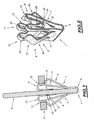
- FIGS. 1 and 2 show an elastic fastener which is designated by the general reference 1 and which makes it possible to fasten two parts to one another, these parts being formed for example by pieces of equipment of a motor vehicle.
- the first piece such as for example the piece 2 comprises a light designated by the general reference 4 in which is engaged the fastener 1.
- the second piece for example 3, is in turn hooked on the fastener 1.
- this elastic fastener has the general shape of a V having an intermediate portion designated by the general reference 5 from which extend the lateral wings designated by the general references 6 and 7 in these figures.
- lateral wings 6 and 7 of the fastener 1 are provided with means forming an outer tab, designated by the general references 8 and 9 in these figures and means forming an inner tab designated by the general references 10 and 11.
- the means forming the external tab of the fastener comprise, as can be seen more clearly in FIG. 2, a central external lug on each side of the fastener, respectively 8a and 9a, provided, for example, near its free end. , means in the form of elastic hook hard point crossing, designated by the general references 12 and 13 in these figures, to ensure the elastic attachment of the fastener on the edges of the light 4 of the first part 2.
- the means forming an inner lug designated by the general references 10 and 11 comprise in turn on each side of the fastener, two inner lugs respectively 14, 15 and 16, 17, disposed on either side of each outer lug 8a and 9a, respectively.
- these inner tabs comprise portions folded towards the inside of the fastener in the direction of the intermediate portion 5 thereof, these portions being for example in the form of bearing plates designated by the general references 18 and 19 in these figures, interconnecting the corresponding tabs on each side of the fastener.
- These support plates are provided with attachment means of the second part 3, these attachment means being for example formed by harpoons such as the harpoon 20 formed on one of the edges of the support plate 18 of connecting the inner tabs 14 and 15.
- folding zones of these internal tabs such as for example the zone designated by the general reference 21 in this figure, for the inner tab 14, are provided at the hook-shaped means 12, 13 of the outer tabs.
- this fastener can be made in one piece by cutting and deformation, for example a sheet blank.
- One of the pieces is designated by the general reference 102 in these figures, while the other piece is designated by the general reference 103.
- the first piece such as for example the piece 102, comprises a light designated by the general reference 104, in which the clip 101 is engaged.
- the second piece for example 103, is hooked on the clip 101.
- this elastic fastener has the general shape of a V having an intermediate portion designated by the general reference 105 from which extend the lateral wings designated by the general references 106 and 107 in these figures.
- These lateral wings 106 and 107 of the fastener 101 are provided with means forming an outer tab, designated by the general references 108 and 109 in these figures and means forming an inner tab designated by the general references 110 and 111.
- the means forming the outer tab of the fastener comprise, as can be seen more clearly in FIG. 2, a central external tab on each side of the fastener, respectively 108a and 109a, provided, for example, near its free end. , means in the form of elastic hook to hard point crossing, designated by the general references 112 and 113 in these figures, to ensure the elastic attachment of the fastener on the edges of the light 104 of the first piece 102.
- the means forming an inner lug designated by the general references 110 and 111 comprise in turn on each side of the fastener, two inner lugs respectively 114, 115 and 116, 117, disposed on either side of each outer lug 108a and 109a, respectively.
- these inner tabs comprise inwardly folded portions of the fastener in the direction of the intermediate portion 105 thereof, these portions ending for example in the form of designated bearing plates. by the general references 118 and 119 in these figures, interconnecting the ends of the corresponding tabs on each side of the fastener.
- the front edges of these support plates form in fact hooking means of the second piece 103 insofar as these support plates are adapted to abut against abutment means complementary to this piece 103.
- the part 103 has a slot 120, against an edge of which abut the plates 118 and 119 of the fastener to ensure the locking in position of this clip and the room 103.
- the inner tabs may include hooking means of the second piece having different shapes from those illustrated.
- stop means of this piece different from an edge of a light thereof can also be envisaged.
- abutment means formed by raised parts such as for example a shoulder of this part, can also be envisaged.
- the folding zones of these internal tabs such as for example the zone designated by the general reference 121 in these figures, for the inner tab 114, are provided at the level of the hook-shaped means 112, 113, tabs external.
- this fastener can also be made in one piece by cutting and deformation, for example a sheet blank.
Landscapes
- Engineering & Computer Science (AREA)
- General Engineering & Computer Science (AREA)
- Mechanical Engineering (AREA)
- Insertion Pins And Rivets (AREA)
- Clamps And Clips (AREA)
- Details Of Connecting Devices For Male And Female Coupling (AREA)
- Table Equipment (AREA)
- Details Of Rigid Or Semi-Rigid Containers (AREA)
- Packages (AREA)
Description
La présente invention concerne une attache élastique pour la fixation de deux pièces l'une sur l'autre.The present invention relates to an elastic fastener for fixing two pieces to one another.
De telles attaches élastiques trouvent de nombreuses applications en particulier dans l'industrie automobile pour assurer la fixation de deux pièces d'équipement d'un véhicule l'une sur l'autre.Such elastic fasteners find many applications particularly in the automotive industry to ensure the attachment of two pieces of equipment of a vehicle one on the other.
Il existe en effet dans l'état de la technique, des attaches élastiques de ce type qui présentent la forme générale d'un V comportant une portion intermédiaire à partir de laquelle s'étendent des ailes latérales.There are indeed in the state of the art, elastic fasteners of this type which have the general shape of a V having an intermediate portion from which extend lateral wings.
Une telle attache est connue du document
Ces ailes latérales de l'attache sont alors munies de moyens formant patte externe comportant des moyens en forme de crochet élastique à franchissement de point dur, d'accrochage de l'attache sur les bords d'une lumière par exemple d'une première pièce et de moyens formant patte interne munis de moyens d'accrochage de la seconde pièce afin d'assurer la fixation de cette seconde pièce sur la première.These lateral wings of the fastener are then provided with means forming an outer lug comprising means in the form of an elastic hook crossing a hard point, hooking the fastener on the edges of a light, for example a first piece. and means forming an inner lug provided with attachment means of the second part in order to ensure the attachment of this second part to the first part.
Dans l'état de la technique, les moyens formant patte interne de l'attache s'étendent à partir de la portion intermédiaire de celle-ci, sur une partie de la hauteur des moyens formant patte externe et définissent un passage de réception de la seconde pièce.In the state of the art, the means forming the inner lug of the fastener extend from the intermediate portion thereof, over a portion of the height of the external lug means and define a receiving passage of the second piece.
Cependant, les attaches de ce type présentent un certain nombre d'inconvénients, notamment au niveau de la difficulté d'introduction de la seconde pièce dans le passage défini par les moyens formant patte interne de l'attache et au niveau de la fiabilité de la fixation.However, the fasteners of this type have a certain number of drawbacks, in particular with regard to the difficulty of introducing the second part into the passage defined by the means forming the inner lug of the fastener and the level of reliability of the fastener. fixation.
Par ailleurs, de telles attaches peuvent également être source de vibration et donc de bruit.Moreover, such fasteners can also be a source of vibration and therefore of noise.
Le but de l'invention est donc de résoudre ces problèmes.The object of the invention is therefore to solve these problems.
A cet effet, l'invention a pour objet une attache élastique pour la fixation de deux pièces l'une sur l'autre présentant la forme générale d'un V comportant une portion intermédiaire à partir de laquelle s'étendent des ailes latérales munies de moyens formant patte externe comportant des moyens en forme de crochet élastique à franchissement de point dur, d'accrochage de l'attache sur les bords d'une lumière d'une première pièce et de moyens formant patte interne munis de moyens d'accrochage de la seconde pièce, afin de fixer cette seconde pièce sur la première, caractérisée en ce que les moyens formant patte interne comportent des portions repliées vers l'intérieur de l'attache en direction de la portion intermédiaire de celle-ci, en ce que les moyens d'accrochage de la seconde pièce sont prévus sur ces portions repliées des moyens formant patte interne et en ce que les zones de pliage de celles-ci sont prévues au niveau des moyens en forme de crochet des moyens formant patte externe.For this purpose, the subject of the invention is an elastic fastener for fastening two parts to one another having the general shape of a V comprising an intermediate portion from which lateral wings provided with means forming an outer lug comprising means in the form of an elastic hook with hard point crossing, hooking of the fastener on the edges of a lumen of a first piece and means forming an inner lug provided with fastening means of the second piece, in order to fix this second piece on the first, characterized in that the means forming an inner lug comprise portions folded towards the inside of the fastener in the direction of the intermediate portion thereof, in that the attachment means of the second piece are provided on these folded portions of the inner tab means and in that the folding areas thereof are provided at the hook-shaped means of the outer tab means.
Suivant d'autres caractéristiques :
- chaque aile latérale de l'attache en V comporte une patte externe centrale de part et d'autre de laquelle est prévue une patte interne latérale ;
- les extrémités des pattes internes latérales de chaque côté de l'attache sont reliées par une plaque d'appui sur les bords de laquelle sont ménagés les moyens d'accrochage de la seconde pièce ;
- les moyens d'accrochage se présentent sous la forme de harpons ;
- les moyens d'accrochage de la seconde pièce sont formés par les extrémités des portions repliées des moyens formant patte interne et sont adaptés pour venir en appui contre des moyens de butée de cette seconde pièce ;
- les extrémités des pattes internes latérales de chaque côté de l'attache sont reliées par une plaque d'appui dont les bords forment les moyens d'accrochage de la seconde pièce ;
- les moyens de butée de la seconde pièce sont formés par des parties en relief de celle-ci ;
- les moyens de butée de la seconde pièce sont formés par un bord d'une lumière de celle-ci ;
- les moyens de butée de la seconde pièce sont formés par un épaulement de celle-ci ; et
- elle est réalisée d'une seule pièce à partir d'un flan de tôle par découpe et déformation de celui-ci.
- each lateral wing of the V-attachment comprises a central outer lug on either side of which is provided a lateral inner lug;
- the ends of the inner lateral tabs on each side of the fastener are connected by a support plate on the edges of which are provided the attachment means of the second part;
- the attachment means are in the form of harpoons;
- the hooking means of the second piece are formed by the ends of the folded portions of the inner lug means and are adapted to bear against abutment means of the second piece;
- the ends of the inner lateral tabs on each side of the fastener are connected by a support plate whose edges form the attachment means of the second part;
- the abutment means of the second piece are formed by raised parts thereof;
- the stop means of the second piece are formed by an edge of a light thereof;
- the abutment means of the second piece are formed by a shoulder thereof; and
- it is made in one piece from a sheet blank by cutting and deformation thereof.
L'invention sera mieux comprise à la lecture de la description qui va suivre, donnée uniquement à titre d'exemple et faite en se référant aux dessins annexés, sur lesquels :
- la Fig.1 représente une vue de côté d'une attache élastique selon l'invention en position de montage et de fixation de deux pièces l'une sur l'autre ;
- la Fig.2 représente une vue en perspective d'une telle attache ;
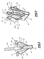
- la Fig.3 représente une variante de réalisation de cette attache ; et
- la Fig.4 représente une vue en perspective de l'attache illustrée sur la figure 3.
- Fig.1 shows a side view of an elastic fastener according to the invention in mounting position and fixing two parts on one another;
- Fig.2 shows a perspective view of such a fastener;
- Fig.3 shows an alternative embodiment of this fastener; and
- 4 is a perspective view of the fastener illustrated in FIG.
On a en effet représenté sur ces figures 1 et 2, une attache élastique qui est désignée par la référence générale 1 et qui permet d'assurer la fixation de deux pièces l'une sur l'autre, ces pièces étant formées par exemple par des pièces d'équipement d'un véhicule automobile.These FIGS. 1 and 2 show an elastic fastener which is designated by the
L'une des pièces est désignée par la référence générale 2 sur ces figures, tandis que l'autre pièce est désignée par la référence générale 3.One of the parts is designated by the
La première pièce, telle que par exemple la pièce 2 comporte une lumière désignée par la référence générale 4 dans laquelle est engagée l'attache 1. La seconde pièce, par exemple 3, est quant à elle accrochée sur l'attache 1.The first piece, such as for example the
A cet effet, cette attache élastique présente la forme générale d'un V comportant une portion intermédiaire désignée par la référence générale 5 à partir de laquelle s'étendent des ailes latérales désignées par les références générales 6 et 7 sur ces figures.For this purpose, this elastic fastener has the general shape of a V having an intermediate portion designated by the
Ces ailes latérales 6 et 7 de l'attache 1, sont munies de moyens formant patte externe, désignés par les références générales 8 et 9 sur ces figures et de moyens formant patte interne désignés par les références générales 10 et 11.These
En fait, les moyens formant patte externe de l'attache comportent comme cela est visible plus clairement sur la figure 2, une patte externe centrale de chaque côté de l'attache, respectivement 8a et 9a, munie par exemple à proximité de son extrémité libre, de moyens en forme de crochet élastique à franchissement de point dur, désignés par les références générales 12 et 13 sur ces figures, pour assurer l'accrochage élastique de l'attache sur les bords de la lumière 4 de la première pièce 2.In fact, the means forming the external tab of the fastener comprise, as can be seen more clearly in FIG. 2, a central external lug on each side of the fastener, respectively 8a and 9a, provided, for example, near its free end. , means in the form of elastic hook hard point crossing, designated by the
Les moyens formant patte interne désignés par les références générales 10 et 11 comprennent quant à eux de chaque côté de l'attache, deux pattes internes respectivement 14, 15 et 16, 17, disposées de part et d'autre de chaque patte externe 8a et 9a, respectivement.The means forming an inner lug designated by the
Comme cela est illustré sur ces figures, ces pattes internes comprennent des portions repliées vers l'intérieur de l'attache en direction de la portion intermédiaire 5 de celle-ci, ces portions se présentant par exemple sous la forme de plaques d'appui désignées par les références générales 18 et 19 sur ces figures, reliant entre elles les pattes correspondantes de chaque côté de l'attache.As illustrated in these figures, these inner tabs comprise portions folded towards the inside of the fastener in the direction of the
Ces plaques d'appui sont munies de moyens d'accrochage de la seconde pièce 3, ces moyens d'accrochage étant par exemple formés par des harpons tels que le harpon 20 ménagé sur l'un des bords de la plaque d'appui 18 de raccordement des pattes internes 14 et 15.These support plates are provided with attachment means of the
En fait, les zones de pliage de ces pattes internes telles que par exemple la zone désignée par la référence générale 21 sur cette figure, pour la patte interne 14, sont prévues au niveau des moyens en forme de crochet 12,13 des pattes externes.In fact, the folding zones of these internal tabs such as for example the zone designated by the
On conçoit alors qu'une telle attache présente un certain nombre d'avantages, notamment au niveau du maintien sans jeu en position de la seconde pièce par rapport à la première. De plus, l'engagement de la seconde pièce entre les pattes internes de cette attache, est également facilité en raison de la présence des zones de pliage de celles-ci qui assurent le guidage de cette seconde pièce lors de son introduction dans l'attache.It is conceivable that such a fastener has a number of advantages, especially in the maintenance-free play position of the second part relative to the first. In addition, the engagement of the second part between the inner lugs of this fastener is also facilitated because of the presence of the folding zones thereof which guide this second part when it is inserted into the fastener. .
Bien entendu, d'autres modes de réalisation encore de cette attache peuvent être envisagés et on notera que celle-ci peut être réalisée d'une seule pièce par découpe et déformation, par exemple d'un flan de tôle.Of course, still other embodiments of this fastener can be envisaged and it will be noted that this can be made in one piece by cutting and deformation, for example a sheet blank.
Ainsi par exemple, on a représenté sur les figures 3 et 4, une variante de cette attache élastique qui est désignée par la référence générale 101 et qui permet d'assurer la fixation de deux pièces l'une sur l'autre, ces pièces étant formées par exemple par des pièces d'équipement d'un véhicule automobile.For example, there is shown in Figures 3 and 4, a variant of this elastic fastener which is designated by the
L'une des pièces est désignée par la référence générale 102 sur ces figures, tandis que l'autre pièce est désignée par la référence générale 103.One of the pieces is designated by the
La première pièce, telle que par exemple la pièce 102, comporte une lumière désignée par la référence générale 104, dans laquelle est engagée l'attache 101. La seconde pièce, par exemple 103, est quant à elle accrochée sur l'attache 101.The first piece, such as for example the
A cet effet, cette attache élastique présente la forme générale d'un V comportant une portion intermédiaire désignée par la référence générale 105 à partir de laquelle s'étendent des ailes latérales désignées par les références générales 106 et 107 sur ces figures.For this purpose, this elastic fastener has the general shape of a V having an intermediate portion designated by the
Ces ailes latérales 106 et 107 de l'attache 101, sont munies de moyens formant patte externe, désignés par les références générales 108 et 109 sur ces figures et de moyens formant patte interne désignés par les références générales 110 et 111.These
En fait, les moyens formant patte externe de l'attache comportent comme cela est visible plus clairement sur la figure 2, une patte externe centrale de chaque côté de l'attache, respectivement 108a et 109a, munie par exemple à proximité de son extrémité libre, de moyens en forme de crochet élastique à franchissement de point dur, désignés par les références générales 112 et 113 sur ces figures, pour assurer l'accrochage élastique de l'attache sur les bords de la lumière 104 de la première pièce 102.In fact, the means forming the outer tab of the fastener comprise, as can be seen more clearly in FIG. 2, a central external tab on each side of the fastener, respectively 108a and 109a, provided, for example, near its free end. , means in the form of elastic hook to hard point crossing, designated by the
Les moyens formant patte interne désignés par les références générales 110 et 111 comprennent quant à eux de chaque côté de l'attache, deux pattes internes respectivement 114, 115 et 116, 117, disposées de part et d'autre de chaque patte externe 108a et 109a, respectivement.The means forming an inner lug designated by the
Comme cela est illustré sur ces figures, ces pattes internes comprennent des portions repliées vers l'intérieur de l'attache en direction de la portion intermédiaire 105 de celle-ci, ces portions se terminant par exemple sous la forme de plaques d'appui désignées par les références générales 118 et 119 sur ces figures, reliant entre elles les extrémités des pattes correspondantes de chaque côté de l'attache.As illustrated in these figures, these inner tabs comprise inwardly folded portions of the fastener in the direction of the
Les bords avant de ces plaques d'appui forment en fait des moyens d'accrochage de la seconde pièce 103 dans la mesure où ces plaques d'appui sont adaptées pour venir en butée contre des moyens de butée complémentaire de cette pièce 103.The front edges of these support plates form in fact hooking means of the
Dans l'exemple de réalisation représenté sur ces figures, la pièce 103 comporte une lumière 120, contre un bord de laquelle viennent en appui les plaques 118 et 119 de l'attache afin d'assurer le blocage en position de cette attache et de la pièce 103.In the embodiment shown in these figures, the
Il va de soi bien entendu que d'autres modes de réalisation peuvent être envisagés.It goes without saying of course that other embodiments can be envisaged.
Ainsi par exemple, les pattes internes peuvent comporter des moyens d'accrochage de la seconde pièce présentant des formes différentes de celles illustrées.For example, the inner tabs may include hooking means of the second piece having different shapes from those illustrated.
De même, des moyens de butée de cette pièce différents d'un bord d'une lumière de celle-ci peuvent également être envisagés.Similarly, stop means of this piece different from an edge of a light thereof can also be envisaged.
Ainsi par exemple, des moyens de butée formés par des parties en relief telles que par exemple un épaulement de cette pièce, peuvent également être envisagés.For example, abutment means formed by raised parts such as for example a shoulder of this part, can also be envisaged.
En fait, les zones de pliage de ces pattes internes, telles que par exemple la zone désignée par la référence générale 121 sur ces figures, pour la patte interne 114, sont prévues au niveau des moyens en forme de crochet 112, 113, des pattes externes.In fact, the folding zones of these internal tabs, such as for example the zone designated by the
On conçoit alors qu'une telle attache présente un certain nombre d'avantages, notamment au niveau du maintien sans jeu en position de la seconde pièce par rapport à la première.It is conceivable that such a fastener has a number of advantages, particularly in the maintenance-free play in position of the second piece relative to the first.
De plus, l'engagement de la seconde pièce entre les pattes internes de cette attache, est également facilité en raison de la présence des zones de pliage de celle-ci, qui assure le guidage de cette seconde pièce lors de son introduction dans l'attache.In addition, the engagement of the second part between the inner tabs of this fastener is also facilitated because of the presence of the folding zones thereof, which ensures the guidance of this second part when it is inserted into the fastener. attached.
Bien entendu, d'autres modes de réalisation encore de cette attache peuvent être envisagés, et on notera que celle-ci peut également être réalisée d'une seule pièce par découpe et déformation, par exemple d'un flan de tôle.Of course, still other embodiments of this fastener can be envisaged, and it will be noted that it can also be made in one piece by cutting and deformation, for example a sheet blank.
Claims (10)
- Spring clip for fixing two parts to each other, in the general shape of a V comprising an intermediate portion (5; 105) from which the lateral wings (6, 7; 106, 107) extend, provided with outward tab means (8, 9; 108, 109) comprising angled spring means (12, 13; 112, 113) for passing a point of resistance and for holding the clip (1; 101) on the edges of a hole (4; 104) in a first part (2; 102) and with inward tab means (10, 11; 110, 111) provided with means (20; 118, 119) for gripping the second part (3; 103), in order to fix this second part (3; 103) to the first (2; 102), which clip is characterized in that the inward tab means (10, 11; 110, 111) comprise portions (18, 19; 118, 119) which are bent toward the interior of the clip in the direction of its intermediate portion (5; 105), in that the means (20; 118, 119) for gripping the second part are situated on these bent portions of the inward tab means, and in that the points where the latter are bent (21; 121) are situated adjacent to the angled means (12, 13; 112, 113) of the outward tab means (8, 9; 108, 109).
- Clip according to Claim 1, characterized in that each lateral wing (6, 7; 106, 107) of the V-shaped clip (1; 101) comprises a central outward tab (8a, 9a; 108a, 109a), situated on each side of which is a lateral inward tab (14, 15, 16, 17; 114, 115, 116, 117).
- Clip according to either of Claims 1 and 2, characterized in that the ends of the lateral inward tabs (14, 15, 16, 17) on each side of the clip are connected by a bearing plate (18, 19), the edges of which have the means (20) for gripping the second part.
- Clip according to Claim 3, characterized in that the gripping means are in the form of barbs.
- Spring clip according to Claim 1 or 2, characterized in that the means (118, 119) for gripping the second part are formed by the ends of the bent portions of the inward tab means and are adapted to bear against abutment means (120) on this second part (103).
- Clip according to Claim 5, characterized in that the ends of the lateral inward tabs (114, 115, 116, 117) on each side of the clip are connected by a bearing plate (118, 119), the edges of which form the means for gripping the second part.
- Clip according to either of Claims 5 and 6, characterized in that the means of abutment of the second part (103) are formed by parts of the latter that are in relief.
- Clip according to Claim 7, characterized in that the means of abutment of the second part are formed by an edge of a hole (120) formed in the latter.
- Clip according to Claim 7, characterized in that the means of abutment of the second part are formed by a shoulder on the latter.
- Clip according to any one of the preceding claims, characterized in that it is made in one piece from a sheet-metal blank by cutting and deforming it.
Applications Claiming Priority (4)
| Application Number | Priority Date | Filing Date | Title |
|---|---|---|---|
| FR0306531 | 2003-05-28 | ||
| FR0306531A FR2855568B1 (en) | 2003-05-28 | 2003-05-28 | ELASTIC ATTACHMENT FOR FASTENING TWO PIECES ON ONE ANOTHER. |
| FR0400556A FR2865248B1 (en) | 2004-01-21 | 2004-01-21 | ELASTIC ATTACHMENT FOR FASTENING TWO PIECES ON ONE ANOTHER. |
| FR4000556 | 2004-01-21 |
Publications (3)
| Publication Number | Publication Date |
|---|---|
| EP1482184A2 EP1482184A2 (en) | 2004-12-01 |
| EP1482184A3 EP1482184A3 (en) | 2006-03-22 |
| EP1482184B1 true EP1482184B1 (en) | 2007-07-04 |
Family
ID=33133112
Family Applications (1)
| Application Number | Title | Priority Date | Filing Date |
|---|---|---|---|
| EP04291331A Active EP1482184B1 (en) | 2003-05-28 | 2004-05-26 | Elastic clip for securing one on the other two workpieces |
Country Status (7)
| Country | Link |
|---|---|
| US (1) | US7051408B2 (en) |
| EP (1) | EP1482184B1 (en) |
| AR (1) | AR044573A1 (en) |
| AT (1) | ATE366372T1 (en) |
| BR (1) | BRPI0402107B1 (en) |
| DE (1) | DE602004007326T2 (en) |
| ES (1) | ES2290644T3 (en) |
Families Citing this family (30)
| Publication number | Priority date | Publication date | Assignee | Title |
|---|---|---|---|---|
| US11577666B2 (en) * | 2012-05-21 | 2023-02-14 | Termax Llc | Arrowhead fastener clip with barbs |
| US9919674B2 (en) * | 2012-02-14 | 2018-03-20 | Termax Llc | Tethered fastener apparatus and method |
| US8128145B2 (en) * | 2005-02-09 | 2012-03-06 | Termax Corporation | Tethered fastener apparatus and method |
| FR2915539B1 (en) * | 2007-04-26 | 2009-07-24 | Attax Sarl | SYSTEM FOR ATTACHING TWO PIECES TO ONE ANOTHER |
| FR2924187B1 (en) * | 2007-11-26 | 2011-04-15 | Attax | ELASTIC ATTACHMENT FOR FIXING TWO PIECES ON ONE ANOTHER |
| US8904607B2 (en) | 2009-03-11 | 2014-12-09 | Illinois Tool Works Inc. | Fastening device |
| ES2383871B1 (en) * | 2010-02-16 | 2013-05-07 | Illinois Tool Works Inc. | QUICK SET CLIP. |
| DE102011114030B4 (en) * | 2011-09-08 | 2019-03-28 | Audi Ag | Spring clip |
| WO2013150741A1 (en) * | 2012-04-02 | 2013-10-10 | 株式会社パイオラックス | Clip and clip device |
| CN104870219B (en) * | 2012-12-28 | 2017-03-22 | 横滨橡胶株式会社 | Pneumatic tire |
| WO2014103063A1 (en) * | 2012-12-28 | 2014-07-03 | 横浜ゴム株式会社 | Pneumatic tire |
| US9657759B2 (en) | 2014-09-10 | 2017-05-23 | Newfrey Llc | U-based fastener with improved rib attachment |
| US9649993B1 (en) * | 2015-08-20 | 2017-05-16 | Termax Corporation | One step assembly fastener clip |
| US10006479B2 (en) * | 2015-08-20 | 2018-06-26 | Termax Llc | Fastener clip assembly with funnel guide |
| US10340166B2 (en) * | 2015-11-22 | 2019-07-02 | George Xinsheng Guo | Substrates handling in a deposition system |
| US10384758B2 (en) * | 2016-01-26 | 2019-08-20 | The Boeing Company | Sandwich panel assembly and method |
| CN108884849B (en) | 2016-03-22 | 2021-02-12 | 伊利诺斯工具制品有限公司 | Fastening clip |
| DE102016012955A1 (en) | 2016-10-29 | 2018-05-03 | Audi Ag | Spring clip |
| WO2019013915A1 (en) | 2017-07-11 | 2019-01-17 | Illinois Tool Works Inc. | Edge protector |
| US10894516B2 (en) | 2017-10-18 | 2021-01-19 | Newfrey Llc | U-base fastener with folded barb and multiple spring arms |
| US10704577B2 (en) | 2017-10-18 | 2020-07-07 | Newfrey Llc | U-base fastener with folded barb |
| US10973321B2 (en) | 2018-09-04 | 2021-04-13 | Steelcase Inc. | Workspace system and components and method for the use thereof |
| FR3087859B1 (en) * | 2018-10-31 | 2020-10-16 | Faurecia Interieur Ind | CLIP AND FIXING KIT INCLUDING SUCH CLIP |
| DE102018127519A1 (en) * | 2018-11-05 | 2020-05-07 | Illinois Tool Works Inc. | Fastening clip for fastening an attachment to a carrier edge |
| US11149774B2 (en) | 2019-10-03 | 2021-10-19 | Newfrey Llc | Bathtub fastener assembly |
| US10968931B1 (en) | 2019-10-17 | 2021-04-06 | Newfrey Llc | Dual component sealing fastener and coupling assembly including same |
| ES2922050B2 (en) * | 2020-01-17 | 2024-01-24 | Illinois Tool Works | METAL RETAINING CLIP |
| USD934063S1 (en) | 2020-01-20 | 2021-10-26 | Illinois Tool Works Inc. | Fastening clip |
| US11744391B2 (en) * | 2020-04-21 | 2023-09-05 | Concept Plastics Limited | Hook for hanging basket |
| US11746812B2 (en) | 2021-05-12 | 2023-09-05 | Newfrey Llc | Dual component sealing fastener and coupling assembly including same |
Family Cites Families (12)
| Publication number | Priority date | Publication date | Assignee | Title |
|---|---|---|---|---|
| US4402118A (en) * | 1981-09-28 | 1983-09-06 | Usm Corporation | Clip for securing a panel to a support |
| DE3245056A1 (en) * | 1982-12-06 | 1984-06-07 | USM Corp., Farmington, Conn. | Elastic clamp |
| DE19702429A1 (en) * | 1997-01-24 | 1998-07-30 | Raymond A & Cie | Clamp system for attaching an attachment to a carrier part |
| JP3463272B2 (en) | 1997-07-01 | 2003-11-05 | 本田技研工業株式会社 | Parts mounting clip |
| US6101686A (en) * | 1998-03-17 | 2000-08-15 | Daimlerchrysler Corporation | Interior trim spring clip |
| US6279207B1 (en) * | 1999-02-01 | 2001-08-28 | Wtpa, Incorporated | Fasteners with increased holding power |
| US6353981B1 (en) * | 1999-02-25 | 2002-03-12 | Termax Corporation | Multi-engagement spring fastener |
| US6141837A (en) | 1999-02-26 | 2000-11-07 | Wisniewski; David M. | EDIAS clip for securing an interior molding to a vehicle frame |
| JP2004519628A (en) * | 2001-03-02 | 2004-07-02 | ニューフレイ リミテッド ライアビリティ カンパニー | U-shaped base fastener with low insertion force |
| US6718599B2 (en) | 2001-06-25 | 2004-04-13 | Termax Corporation | Spring fastener with ergonomically balanced removal to insertion force ratio |
| US6691380B2 (en) * | 2001-07-31 | 2004-02-17 | Eustathios Vassiliou Revocable Trust | Fasteners of increased holding power |
| JP2005527752A (en) | 2002-05-28 | 2005-09-15 | ニューフレイ リミテッド ライアビリティ カンパニー | Elastic clip type fastener and method of manufacturing the same |
-
2004
- 2004-05-26 BR BRPI0402107-0A patent/BRPI0402107B1/en not_active IP Right Cessation
- 2004-05-26 ES ES04291331T patent/ES2290644T3/en active Active
- 2004-05-26 DE DE602004007326T patent/DE602004007326T2/en active Active
- 2004-05-26 AT AT04291331T patent/ATE366372T1/en not_active IP Right Cessation
- 2004-05-26 EP EP04291331A patent/EP1482184B1/en active Active
- 2004-05-27 US US10/854,760 patent/US7051408B2/en active Active
- 2004-05-28 AR ARP040101859A patent/AR044573A1/en not_active Application Discontinuation
Also Published As
| Publication number | Publication date |
|---|---|
| BRPI0402107B1 (en) | 2015-06-30 |
| US20050000063A1 (en) | 2005-01-06 |
| DE602004007326T2 (en) | 2008-03-06 |
| ES2290644T3 (en) | 2008-02-16 |
| BRPI0402107A (en) | 2005-05-17 |
| DE602004007326D1 (en) | 2007-08-16 |
| ATE366372T1 (en) | 2007-07-15 |
| EP1482184A2 (en) | 2004-12-01 |
| EP1482184A3 (en) | 2006-03-22 |
| US7051408B2 (en) | 2006-05-30 |
| AR044573A1 (en) | 2005-09-21 |
Similar Documents
| Publication | Publication Date | Title |
|---|---|---|
| EP1482184B1 (en) | Elastic clip for securing one on the other two workpieces | |
| EP1985871B1 (en) | System for attaching two parts to one another | |
| EP1557572B1 (en) | Clip for fixation of two pieces one another | |
| EP1760328B1 (en) | Elastic connecter for the fixation of two elements upon each other | |
| EP3561360B1 (en) | Tightening system with folding tabs for connecting tubes | |
| FR3049533B1 (en) | DEVICE FOR MAINTAINING AT LEAST ONE OBJECT IN AN INTERIOR AREA OF A MOTOR VEHICLE | |
| EP2220384B1 (en) | Spring clip for fixing two components to each other | |
| EP1722111B1 (en) | Fastening device for fastening a metal profile on a support | |
| FR2766905A1 (en) | Folded section girder for building construction | |
| EP1728687A1 (en) | Arrangement for mounting a decorative element on an automobile body part. | |
| EP0569297B1 (en) | Holding device for several conduits, cables or the like | |
| FR2865248A1 (en) | Fastener for fixing two equipment parts of motor vehicle one above another, has harpoon of part arranged on one edge of plate for connecting internal prongs whose folding zones are provided at level of hooks of external prongs | |
| EP1249653B1 (en) | Cable tray element | |
| EP2867098B1 (en) | Fastening device for joining the side end of a bumper skirt to a vehicle body panel | |
| EP2006553A1 (en) | Arrangement for fixing a part to another part | |
| EP3442852B1 (en) | Arrangement of a shield and a body element of a motor vehicle, in particular a body element made from sheet metal | |
| EP2177775B1 (en) | Arrangement for assembling two parts such as two panels with the help of a caged nut device | |
| FR2794501A1 (en) | Panel fitting screw nut for motor vehicle has threaded base with elastic hooks engaging through panel | |
| FR2855568A1 (en) | Fastener for fixing two equipment parts of motor vehicle one above another, has harpoon of part arranged on one edge of plate for connecting internal prongs whose folding zones are provided at level of hooks of external prongs | |
| EP0169747A1 (en) | Bumpers for a vehicle | |
| WO2013038106A2 (en) | Cooling arrangement for a motor vehicle | |
| FR2899655A1 (en) | Elastic fastener for fixing equipment parts of motor vehicle, has lateral wing extending from branch of intermediate portion, and hooking unit with hard point release on part, where harpoons are formed by inclined cutting of branches | |
| FR2899656A1 (en) | Elastic fastener for fixing equipment parts of motor vehicle, has lateral wing, extended around intermediate portion engaged on one part, including support plate and gripping unit with hard point release, on edges of hole of another part | |
| EP0685655A1 (en) | Resilient fastening clip | |
| EP0865974A1 (en) | Steering wheel, in particular for an automotive vehicle |
Legal Events
| Date | Code | Title | Description |
|---|---|---|---|
| PUAI | Public reference made under article 153(3) epc to a published international application that has entered the european phase |
Free format text: ORIGINAL CODE: 0009012 |
|
| AK | Designated contracting states |
Kind code of ref document: A2 Designated state(s): AT BE BG CH CY CZ DE DK EE ES FI FR GB GR HU IE IT LI LU MC NL PL PT RO SE SI SK TR |
|
| AX | Request for extension of the european patent |
Extension state: AL HR LT LV MK |
|
| PUAL | Search report despatched |
Free format text: ORIGINAL CODE: 0009013 |
|
| AK | Designated contracting states |
Kind code of ref document: A3 Designated state(s): AT BE BG CH CY CZ DE DK EE ES FI FR GB GR HU IE IT LI LU MC NL PL PT RO SE SI SK TR |
|
| AX | Request for extension of the european patent |
Extension state: AL HR LT LV MK |
|
| 17P | Request for examination filed |
Effective date: 20060914 |
|
| GRAP | Despatch of communication of intention to grant a patent |
Free format text: ORIGINAL CODE: EPIDOSNIGR1 |
|
| AKX | Designation fees paid |
Designated state(s): AT BE BG CH CY CZ DE DK EE ES FI FR GB GR HU IE IT LI LU MC NL PL PT RO SE SI SK TR |
|
| GRAS | Grant fee paid |
Free format text: ORIGINAL CODE: EPIDOSNIGR3 |
|
| GRAA | (expected) grant |
Free format text: ORIGINAL CODE: 0009210 |
|
| AK | Designated contracting states |
Kind code of ref document: B1 Designated state(s): AT BE BG CH CY CZ DE DK EE ES FI FR GB GR HU IE IT LI LU MC NL PL PT RO SE SI SK TR |
|
| REG | Reference to a national code |
Ref country code: GB Ref legal event code: FG4D Free format text: NOT ENGLISH |
|
| REG | Reference to a national code |
Ref country code: CH Ref legal event code: EP |
|
| REG | Reference to a national code |
Ref country code: IE Ref legal event code: FG4D Free format text: LANGUAGE OF EP DOCUMENT: FRENCH |
|
| REF | Corresponds to: |
Ref document number: 602004007326 Country of ref document: DE Date of ref document: 20070816 Kind code of ref document: P |
|
| GBT | Gb: translation of ep patent filed (gb section 77(6)(a)/1977) |
Effective date: 20071001 |
|
| NLV1 | Nl: lapsed or annulled due to failure to fulfill the requirements of art. 29p and 29m of the patents act | ||
| PG25 | Lapsed in a contracting state [announced via postgrant information from national office to epo] |
Ref country code: FI Free format text: LAPSE BECAUSE OF FAILURE TO SUBMIT A TRANSLATION OF THE DESCRIPTION OR TO PAY THE FEE WITHIN THE PRESCRIBED TIME-LIMIT Effective date: 20070704 Ref country code: SI Free format text: LAPSE BECAUSE OF FAILURE TO SUBMIT A TRANSLATION OF THE DESCRIPTION OR TO PAY THE FEE WITHIN THE PRESCRIBED TIME-LIMIT Effective date: 20070704 Ref country code: PT Free format text: LAPSE BECAUSE OF FAILURE TO SUBMIT A TRANSLATION OF THE DESCRIPTION OR TO PAY THE FEE WITHIN THE PRESCRIBED TIME-LIMIT Effective date: 20071204 Ref country code: NL Free format text: LAPSE BECAUSE OF FAILURE TO SUBMIT A TRANSLATION OF THE DESCRIPTION OR TO PAY THE FEE WITHIN THE PRESCRIBED TIME-LIMIT Effective date: 20070704 Ref country code: BG Free format text: LAPSE BECAUSE OF FAILURE TO SUBMIT A TRANSLATION OF THE DESCRIPTION OR TO PAY THE FEE WITHIN THE PRESCRIBED TIME-LIMIT Effective date: 20071004 |
|
| REG | Reference to a national code |
Ref country code: ES Ref legal event code: FG2A Ref document number: 2290644 Country of ref document: ES Kind code of ref document: T3 |
|
| PG25 | Lapsed in a contracting state [announced via postgrant information from national office to epo] |
Ref country code: AT Free format text: LAPSE BECAUSE OF FAILURE TO SUBMIT A TRANSLATION OF THE DESCRIPTION OR TO PAY THE FEE WITHIN THE PRESCRIBED TIME-LIMIT Effective date: 20070704 Ref country code: PL Free format text: LAPSE BECAUSE OF FAILURE TO SUBMIT A TRANSLATION OF THE DESCRIPTION OR TO PAY THE FEE WITHIN THE PRESCRIBED TIME-LIMIT Effective date: 20070704 |
|
| PG25 | Lapsed in a contracting state [announced via postgrant information from national office to epo] |
Ref country code: GR Free format text: LAPSE BECAUSE OF FAILURE TO SUBMIT A TRANSLATION OF THE DESCRIPTION OR TO PAY THE FEE WITHIN THE PRESCRIBED TIME-LIMIT Effective date: 20071005 Ref country code: DK Free format text: LAPSE BECAUSE OF FAILURE TO SUBMIT A TRANSLATION OF THE DESCRIPTION OR TO PAY THE FEE WITHIN THE PRESCRIBED TIME-LIMIT Effective date: 20070704 |
|
| PLBE | No opposition filed within time limit |
Free format text: ORIGINAL CODE: 0009261 |
|
| STAA | Information on the status of an ep patent application or granted ep patent |
Free format text: STATUS: NO OPPOSITION FILED WITHIN TIME LIMIT |
|
| PG25 | Lapsed in a contracting state [announced via postgrant information from national office to epo] |
Ref country code: SK Free format text: LAPSE BECAUSE OF FAILURE TO SUBMIT A TRANSLATION OF THE DESCRIPTION OR TO PAY THE FEE WITHIN THE PRESCRIBED TIME-LIMIT Effective date: 20070704 Ref country code: CZ Free format text: LAPSE BECAUSE OF FAILURE TO SUBMIT A TRANSLATION OF THE DESCRIPTION OR TO PAY THE FEE WITHIN THE PRESCRIBED TIME-LIMIT Effective date: 20070704 |
|
| 26N | No opposition filed |
Effective date: 20080407 |
|
| PG25 | Lapsed in a contracting state [announced via postgrant information from national office to epo] |
Ref country code: SE Free format text: LAPSE BECAUSE OF FAILURE TO SUBMIT A TRANSLATION OF THE DESCRIPTION OR TO PAY THE FEE WITHIN THE PRESCRIBED TIME-LIMIT Effective date: 20071004 Ref country code: RO Free format text: LAPSE BECAUSE OF FAILURE TO SUBMIT A TRANSLATION OF THE DESCRIPTION OR TO PAY THE FEE WITHIN THE PRESCRIBED TIME-LIMIT Effective date: 20070704 |
|
| PG25 | Lapsed in a contracting state [announced via postgrant information from national office to epo] |
Ref country code: EE Free format text: LAPSE BECAUSE OF FAILURE TO SUBMIT A TRANSLATION OF THE DESCRIPTION OR TO PAY THE FEE WITHIN THE PRESCRIBED TIME-LIMIT Effective date: 20070704 |
|
| PG25 | Lapsed in a contracting state [announced via postgrant information from national office to epo] |
Ref country code: CY Free format text: LAPSE BECAUSE OF FAILURE TO SUBMIT A TRANSLATION OF THE DESCRIPTION OR TO PAY THE FEE WITHIN THE PRESCRIBED TIME-LIMIT Effective date: 20070704 |
|
| PG25 | Lapsed in a contracting state [announced via postgrant information from national office to epo] |
Ref country code: HU Free format text: LAPSE BECAUSE OF FAILURE TO SUBMIT A TRANSLATION OF THE DESCRIPTION OR TO PAY THE FEE WITHIN THE PRESCRIBED TIME-LIMIT Effective date: 20080105 |
|
| PG25 | Lapsed in a contracting state [announced via postgrant information from national office to epo] |
Ref country code: TR Free format text: LAPSE BECAUSE OF FAILURE TO SUBMIT A TRANSLATION OF THE DESCRIPTION OR TO PAY THE FEE WITHIN THE PRESCRIBED TIME-LIMIT Effective date: 20070704 |
|
| REG | Reference to a national code |
Ref country code: FR Ref legal event code: PLFP Year of fee payment: 13 |
|
| REG | Reference to a national code |
Ref country code: FR Ref legal event code: PLFP Year of fee payment: 14 |
|
| PGFP | Annual fee paid to national office [announced via postgrant information from national office to epo] |
Ref country code: IE Payment date: 20170502 Year of fee payment: 14 Ref country code: MC Payment date: 20170419 Year of fee payment: 14 |
|
| PGFP | Annual fee paid to national office [announced via postgrant information from national office to epo] |
Ref country code: BE Payment date: 20170531 Year of fee payment: 14 Ref country code: LU Payment date: 20170414 Year of fee payment: 14 |
|
| REG | Reference to a national code |
Ref country code: FR Ref legal event code: PLFP Year of fee payment: 15 |
|
| REG | Reference to a national code |
Ref country code: CH Ref legal event code: PL |
|
| REG | Reference to a national code |
Ref country code: BE Ref legal event code: MM Effective date: 20180531 |
|
| PG25 | Lapsed in a contracting state [announced via postgrant information from national office to epo] |
Ref country code: MC Free format text: LAPSE BECAUSE OF NON-PAYMENT OF DUE FEES Effective date: 20180601 |
|
| REG | Reference to a national code |
Ref country code: IE Ref legal event code: MM4A |
|
| PG25 | Lapsed in a contracting state [announced via postgrant information from national office to epo] |
Ref country code: LI Free format text: LAPSE BECAUSE OF NON-PAYMENT OF DUE FEES Effective date: 20180531 Ref country code: CH Free format text: LAPSE BECAUSE OF NON-PAYMENT OF DUE FEES Effective date: 20180531 |
|
| PG25 | Lapsed in a contracting state [announced via postgrant information from national office to epo] |
Ref country code: LU Free format text: LAPSE BECAUSE OF NON-PAYMENT OF DUE FEES Effective date: 20180526 |
|
| PG25 | Lapsed in a contracting state [announced via postgrant information from national office to epo] |
Ref country code: IE Free format text: LAPSE BECAUSE OF NON-PAYMENT OF DUE FEES Effective date: 20180526 |
|
| PG25 | Lapsed in a contracting state [announced via postgrant information from national office to epo] |
Ref country code: BE Free format text: LAPSE BECAUSE OF NON-PAYMENT OF DUE FEES Effective date: 20180531 |
|
| REG | Reference to a national code |
Ref country code: FR Ref legal event code: PLFP Year of fee payment: 20 |
|
| PGFP | Annual fee paid to national office [announced via postgrant information from national office to epo] |
Ref country code: IT Payment date: 20230517 Year of fee payment: 20 Ref country code: FR Payment date: 20230412 Year of fee payment: 20 Ref country code: ES Payment date: 20230607 Year of fee payment: 20 Ref country code: DE Payment date: 20230510 Year of fee payment: 20 |
|
| PGFP | Annual fee paid to national office [announced via postgrant information from national office to epo] |
Ref country code: GB Payment date: 20230519 Year of fee payment: 20 |