EP2177775B1 - Arrangement for assembling two parts such as two panels with the help of a caged nut device - Google Patents
Arrangement for assembling two parts such as two panels with the help of a caged nut device Download PDFInfo
- Publication number
- EP2177775B1 EP2177775B1 EP09172754A EP09172754A EP2177775B1 EP 2177775 B1 EP2177775 B1 EP 2177775B1 EP 09172754 A EP09172754 A EP 09172754A EP 09172754 A EP09172754 A EP 09172754A EP 2177775 B1 EP2177775 B1 EP 2177775B1
- Authority
- EP
- European Patent Office
- Prior art keywords
- panel
- nut
- cage
- lugs
- screw
- Prior art date
- Legal status (The legal status is an assumption and is not a legal conclusion. Google has not performed a legal analysis and makes no representation as to the accuracy of the status listed.)
- Active
Links
- 230000000694 effects Effects 0.000 claims description 6
- 230000000284 resting effect Effects 0.000 claims description 3
- 210000002105 tongue Anatomy 0.000 description 2
- 238000005452 bending Methods 0.000 description 1
- 238000006073 displacement reaction Methods 0.000 description 1
- 230000002452 interceptive effect Effects 0.000 description 1
- 230000014759 maintenance of location Effects 0.000 description 1
- 238000000034 method Methods 0.000 description 1
- 230000000717 retained effect Effects 0.000 description 1
Images
Classifications
-
- F—MECHANICAL ENGINEERING; LIGHTING; HEATING; WEAPONS; BLASTING
- F16—ENGINEERING ELEMENTS AND UNITS; GENERAL MEASURES FOR PRODUCING AND MAINTAINING EFFECTIVE FUNCTIONING OF MACHINES OR INSTALLATIONS; THERMAL INSULATION IN GENERAL
- F16B—DEVICES FOR FASTENING OR SECURING CONSTRUCTIONAL ELEMENTS OR MACHINE PARTS TOGETHER, e.g. NAILS, BOLTS, CIRCLIPS, CLAMPS, CLIPS OR WEDGES; JOINTS OR JOINTING
- F16B37/00—Nuts or like thread-engaging members
- F16B37/04—Devices for fastening nuts to surfaces, e.g. sheets, plates
- F16B37/044—Nut cages
-
- F—MECHANICAL ENGINEERING; LIGHTING; HEATING; WEAPONS; BLASTING
- F16—ENGINEERING ELEMENTS AND UNITS; GENERAL MEASURES FOR PRODUCING AND MAINTAINING EFFECTIVE FUNCTIONING OF MACHINES OR INSTALLATIONS; THERMAL INSULATION IN GENERAL
- F16B—DEVICES FOR FASTENING OR SECURING CONSTRUCTIONAL ELEMENTS OR MACHINE PARTS TOGETHER, e.g. NAILS, BOLTS, CIRCLIPS, CLAMPS, CLIPS OR WEDGES; JOINTS OR JOINTING
- F16B37/00—Nuts or like thread-engaging members
- F16B37/04—Devices for fastening nuts to surfaces, e.g. sheets, plates
- F16B37/041—Releasable devices
- F16B37/043—Releasable devices with snap action
Definitions
- the invention relates to an assembly arrangement of two parts, such as two panels, of the type comprising a cage nut device for mounting the cage holding the nut on a first panel, the cage comprising a nut housing part. and end tabs in the form of a hooking element of the cage to ensure the retention of the nut of the first face of the panel by passing through a recess formed in the panel and locking the cage by the elements hook engaging the second face of the panel, behind the recess, and a fixing screw of the second panel on the second face of the first panel when it is screwed into the nut, the head of the screw bearing on the free face of the second panel (cf. FR 2 487 456 A ), corresponding to the preamble of independent claim 1.
- the invention aims to overcome these disadvantages.
- the arrangement according to the invention comprises the features of claim 1.
- the arrangement is characterized in that the housing portion of the nut of the cage has the shape of a U whose branches have a length greater than the height of the nut so that when the cage is mounted on the panel, with the nut resting on the bottom of the cage, the non-facing portion of the nut by extending the length of the tabs 10 increases the elastic deformability thereof.
- the arrangement is characterized in that one and the same cage is usable for a plurality of panels of different thicknesses, the tabs having a sufficient length for mounting on the thickest panel, and consequently greater to the thickness of the thinnest panel.
- the arrangement is characterized in that the lugs have recesses adapted to prevent the tabs during assembly of the panels come into contact with the screw.
- the arrangement is characterized in that a portion of each tab, in the form of a tongue, of the portion engaged in the recess of the first panel is retained and constitutes a lateral stiffening bar of the paw.
- the arrangement is characterized in that it comprises a U-shaped cage, made by folding a starting blank and having branches whose end portions are configured to comprise support shoulders on the underside of the first panel and mounting brackets with hooking end, and in that the inner face of the branches has spacing bosses branches under the effect of the displacement of the nut in its assembly position under the effect of the screw engaging in the nut.
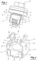
- the figure 1 shows the arrangement according to the invention 1 in its assembly position of two panels 2 and 3.
- the arrangement 1 comprises a cage 5 adapted to retain a nut 6 and to premount on the free bottom face 7 of the panel 2 of so that the nut can receive a screw 4 for fixing the second panel 3 on the first panel 2 and thus assembling the two panels.
- the cage 5 comprises a portion 9 for housing the nut 6, of generally parallelepipedal shape, adapted to the rectangular shape of the nut, and two lugs 10 for placing and locking the cage holding the The tabs are intended to extend through a recess 8 made in the panel 2 and hang on the panel behind this recess.
- the portion 9 housing the nut has the shape of a U whose base 12 serves as bottom wall and support of the nut and whose branches 13 extend substantially perpendicularly to the base 12 and constitute lateral support walls of the nut. It is trapped in the cage part 9, at the other two opposite sides of the nut, by retaining tongues 14, two of which are provided at each lateral edge of the base 12. These tabs extend perpendicularly in the direction of the tabs 10, from the base 12. This base has in its central zone a recess for passage of the screw 7 during its screwing into the nut 6.
- the lateral branches 13 of the are bent, perpendicularly, a first time inwards, to form bearing shoulders 15 during assembly of the cage on the panel 2, and a second time, to form the mounting lugs 10 whose free ends are bent outwardly to form hooking elements 16 of the cage on the rear face 26 of the panel 2, as shown in FIG. figure 3 .
- the height of the housing portion 9 of the cage is greater than the height of the nut 6, for example two or more times. Since when mounting the cage on the panel 2, the nut 6 rests on the bottom of the housing 9, as seen on the figure 2 , the intrinsic flexibility of the tabs 10 during assembly is increased by the free length of the legs 13, that is to say the branch portion which is not opposite the nut.
- each tab 10 retains at its birth a bar-shaped cross-section 20 which remains connected to the corresponding shoulder 15 but is cut along the lateral edge 21 of the recess up to the level of the fold 22.
- the transverse bar 20 opposes deformation, especially in torsion, of the part of the lugs 10, which is engaged in the passage recess 8 made in the panel 2, during the tightening of the screw and ensures the rigidity of the cage during clamping
- each lateral branch 13 of the cage carries, on its inner face, below the shoulder 15 which follows this branch, a boss 24 intended to produce a spacing of the branches when the nut 6 moves from its position resting on the base wall 12 towards the free underside of the panel when the screw engages in the nut, during the assembly of the two panels.
- the figure 1 shows the nut in its final position, at the end of the assembly, in which the upper face of the nut bears against the inner face of the shoulders 15.
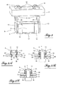
- FIGS 4A to 4C illustrate the device according to the invention in three significant phases of the assembly process of the two sheets 2 and 3.
- the Figure 4A shows the mounting of the cage enclosing the nut 6 on the first panel 2.
- the nut 6 is supported on the bottom wall 12 of the cage.
- the mounting tabs 10 whose length is greater than the thickness of the panel extend through the recess 8 of the panel.
- the flexibility of the tabs increased by the free length of the branches 13, that is to say not facing the nut, and allows manual mounting, because the tabs are sufficiently elastically deformable to approach when their engagement in the recess 8 and then move away so that the hooking elements 16 can come into engagement behind the recess, on the rear face 26 thereof.
- the length of the tabs is chosen to have a length much greater than the thickness of the thinnest panel to which the cage is applicable and so that this cage is still usable for several panels of a gradually increasing thickness.
- the Figure 4B shows the arrangement at an intermediate assembly phase.
- the second panel 3 is being fixed on the first panel 2 under the effect of the screw 4 which engages in the nut 6.
- the face 28 of the panel 3, opposite the face rear 26 of the panel 1 comes into contact with the fastening elements 16 of the mounting lugs 10.
- the head of the screw bears on the outer face 29 of the panel 3.
- the nut 6 moves from its position on the base 12 of the cage ( Figure 4A ) towards the shoulders 15 of the cage then bearing against the free lower face 7 of the first panel 2.
- the lateral branches 13 of the cage are spaced apart and thus the mounting lugs 10 moved towards the edges 30 of the recess of the panel 2 , by the engagement of the nut on the bosses 24 under the shoulders.
- the figure 4C shows the arrangement at the end of the assembly of the two panels, that is to say at the stage that also shows the figure 1 .
- the tightening of the screw 9 has the effect that the two panels are tightened against each other by crushing between them the fastening elements 16.
- the stiffening bars 20 do not deform, while the tabs 10 deform by bending inward, but without interfering with the thread of the screw.
- the bars 20 have a height which is less than the thickness of the thinnest panel for which the cage is usable.
- the cages are made, in a manner known per se, by cutting a blank of a strip and are then formed in a press by deforming the blank around the nut placed on this blank.
- a cage having a sufficient leg length to be mounted on panels whose thickness varies between 0.7 to 1.7 millimeters.
- a second cage could be usable for sheets between 1.7 and 3 millimeters thick and a third for panels with a thickness of between 3 millimeters and 4.5 millimeters.
Landscapes
- Engineering & Computer Science (AREA)
- General Engineering & Computer Science (AREA)
- Mechanical Engineering (AREA)
- Connection Of Plates (AREA)
Abstract
Description
L'invention concerne un agencement d'assemblage de deux pièces, telles que deux panneaux, du type comprenant un dispositif écrou à cage pour monter la cage retenant l'écrou sur un premier panneau, la cage comportant une partie de logement de l'écrou et des pattes à extrémités en forme d'élément d'accrochage de la cage pour assurer la retenue de l'écrou de la première face du panneau par passage à travers d'un évidement pratiqué dans le panneau et blocage de la cage par les éléments de crochet venant en prise sur la deuxième face du panneau, derrière l'évidement, et une vis de fixation du second panneau sur la deuxième face du premier panneau lorsqu'elle est vissée dans l'écrou, la tête de la vis prenant appui sur la face libre du second panneau (cf.
Des agencements de ce type, qui sont connus, présentent l'inconvénient que la longueur des pattes est adaptée à l'épaisseur du panneau sur lequel est monté la cage. Par conséquent, il faut une cage pour un groupe de panneaux dont les épaisseurs ne diffèrent que de peu. D'autre part, les pattes des cages pour des panneaux minces étant courtes, elles sont relativement rigides, si bien que les cages sont difficiles à mettre en place sur le panneau et à enlever de celui-ci, sans utilisation d'un outil approprié.Arrangements of this type, which are known, have the disadvantage that the length of the tabs is adapted to the thickness of the panel on which is mounted the cage. Therefore, it takes a cage for a group of panels whose thicknesses differ only slightly. On the other hand, the legs of the cages for thin panels being short, they are relatively rigid, so that the cages are difficult to set up on the panel and to remove from it, without the use of a suitable tool .
L'invention a pour but de pallier ces inconvénients.The invention aims to overcome these disadvantages.
Pour atteindre ce but, l'agencement selon l'invention comprend les caractéristiques de la revendication 1.To achieve this purpose, the arrangement according to the invention comprises the features of
Selon encore une caractéristique préférable l'agencement est caractérisé en ce que la partie de logement de l'écrou de la cage présente la forme d'un U dont les branches présentent une longueur supérieure à la hauteur de l'écrou de façon que, lorsque la cage est montée sur le panneau, avec l'écrou reposant sur le fond de la cage, la partie non en regard de l'écrou en prolongeant la longueur des pattes 10 augmente la déformabilité élastique de celles-ci.According to another preferable characteristic, the arrangement is characterized in that the housing portion of the nut of the cage has the shape of a U whose branches have a length greater than the height of the nut so that when the cage is mounted on the panel, with the nut resting on the bottom of the cage, the non-facing portion of the nut by extending the length of the
Selon encore une caractéristique préférable, l'agencement est caractérisé en ce qu'une même cage est utilisable pour une pluralité de panneaux d'épaisseurs différentes, les pattes présentant une longueur suffisante pour le montage sur le panneau le plus épais, et supérieure en conséquence à l'épaisseur du panneau le plus mince.According to another preferable feature, the arrangement is characterized in that one and the same cage is usable for a plurality of panels of different thicknesses, the tabs having a sufficient length for mounting on the thickest panel, and consequently greater to the thickness of the thinnest panel.
Selon encore une caractéristique préférable, l'agencement est caractérisé en ce que les pattes présentent des évidements adaptés pour empêcher que les pattes lors de l'assemblage des panneaux viennent en contact avec la vis.According to another preferred feature, the arrangement is characterized in that the lugs have recesses adapted to prevent the tabs during assembly of the panels come into contact with the screw.
Selon encore une caractéristique préférable, l'agencement est caractérisé en ce qu'une partie de chaque patte, en forme d'une languette, de la partie engagée dans l'évidement du premier panneau est conservée et constitue une barrette de rigidification latérale de la patte.According to another preferable characteristic, the arrangement is characterized in that a portion of each tab, in the form of a tongue, of the portion engaged in the recess of the first panel is retained and constitutes a lateral stiffening bar of the paw.
Selon encore une caractéristique préférable, l'agencement est caractérisé en ce qu'il comprend une cage en forme d'un U, réalisée par pliage d'un flan de départ et ayant des branches dont les parties d'extrémité sont configurées pour comporter des épaulements d'appui sur la face inférieure du premier panneau et des pattes de montage à extrémité d'accrochage, et en ce que la face interne des branches présente des bossages d'écartement des branches sous l'effet du déplacement de l'écrou dans sa position d'assemblage sous l'effet de la vis s'engageant dans l'écrou.According to another preferable feature, the arrangement is characterized in that it comprises a U-shaped cage, made by folding a starting blank and having branches whose end portions are configured to comprise support shoulders on the underside of the first panel and mounting brackets with hooking end, and in that the inner face of the branches has spacing bosses branches under the effect of the displacement of the nut in its assembly position under the effect of the screw engaging in the nut.
L'invention sera mieux comprise, et d'autres buts, caractéristiques, détails et avantages de celle-ci apparaîtront plus clairement au cours de la description explicative qui va suivre faite en référence aux dessins schématiques annexés donnés uniquement à titre d'exemple illustrant un mode de réalisation de l'invention et dans desquels :
- la
figure 1 est une vue en perspective de l'agencement de fixation selon l'invention dans sa position d'assemblage de deux panneaux ; - la
figure 2 est une vue en perspective de la cage retenant l'écrou selon l'invention ; - la
figure 3 est une vue en perspective montrant la cage de lafigure 2 dans sa position montée sur un panneau, et - les
figures 4A à 4C illustrent schématiquement l'agencement selon l'invention dans trois positions différentes d'assemblage de deux panneaux.
- the
figure 1 is a perspective view of the fastening arrangement according to the invention in its assembly position of two panels; - the
figure 2 is a perspective view of the cage holding the nut according to the invention; - the
figure 3 is a perspective view showing the cage of thefigure 2 in its mounted position on a panel, and - the
Figures 4A to 4C schematically illustrate the arrangement according to the invention in three different positions of assembly of two panels.
La
Plus précisément, la cage 5 comprend une partie 9 de logement de l'écrou 6, de forme générale parallélépipédique, adaptée à la forme rectangulaire de l'écrou, et deux pattes 10 de mise en place et de blocage de la cage retenant l'écrou sur le panneau 2. Les pattes sont destinées à s'étendre à travers un évidement de passage 8 pratiqué dans le panneau 2 et s'accrocher sur le panneau derrière cet évidement.More specifically, the
La partie 9 de logement de l'écrou présente la forme d'un U dont la base 12 sert de paroi de fond et d'appui de l'écrou et dont les branches 13 s'étendent sensiblement perpendiculairement à la base 12 et constituent des parois d'appui latérales de l'écrou. Celui-ci est emprisonné dans la partie de cage 9, aux deux autres côtés opposés de l'écrou, par des languettes de retenue 14 dont deux sont prévues au niveau de chaque bord latéral de la base 12. Ces languettes s'étendent perpendiculairement en direction des pattes 10, à partir de la base 12. Cette base présente dans sa zone centrale un évidement de passage de la vis 7 lors de son vissage dans l'écrou 6. A leurs extrémités libres, les branches latérales 13 de la cage sont recourbées, perpendiculairement, une première fois vers l'intérieur, pour former des épaulements d'appui 15 lors du montage de la cage sur le panneau 2, et une deuxième fois, pour former les pattes de montage 10 dont les extrémités libres sont recourbées vers l'extérieur pour former des éléments d'accrochage 16 de la cage sur la face arrière 26 du panneau 2, comme l'illustre la
Comme il ressort des figures, la hauteur de la partie de logement 9 de la cage, c'est-à-dire la longueur des branches 13, est supérieure à la hauteur de l'écrou 6, par exemple de deux fois ou plus. Etant donné que lors du montage de la cage sur le panneau 2, l'écrou 6 repose sur le fond du logement 9, comme on le voit sur la
D'autre part, les pattes 10 ne sont pas pleines et présentent chacune un évidement 18 dont les bords sont parallèles aux bords extérieurs des parois. Ces évidements empêchent que les pattes 10 lors du serrage de la vis se déformant par arrondissement vers l'intérieur en direction de la vis, viennent en contact avec la vis et frotte sur le filetage de celle-ci. Grâce aux évidements, on supprime ce défaut. Pour agir contre la diminution de la rigidité en torsion de la cage, qui en résulte, chaque patte 10 conserve au niveau de sa naissance une partie transversale en forme de barrette 20 qui reste reliée à l'épaulement correspondant 15 mais est découpée le long du bord latéral 21 de l'évidement jusqu'au niveau du pli 22. La barrette transversale 20 s'oppose à une déformation notamment en torsion de la partie des pattes 10, qui est engagée dans l'évidement de passage 8 pratiqué dans le panneau 2, lors du serrage de la vis et assure la rigidité de la cage lors du serrageOn the other hand, the
On constate encore, notamment en se référant à la
Les
La
La
La
Il est à noter que les barrettes 20 présentent une hauteur qui est inférieure à l'épaisseur du panneau le plus mince pour lequel la cage est utilisable.It should be noted that the
Il est encore à noter que les cages sont réalisées, de façon connue en soi, par découpe d'un flan d'un feuillard et sont ensuite formées dans une presse par déformation du flan autour de l'écrou posé sur ce flan.It should also be noted that the cages are made, in a manner known per se, by cutting a blank of a strip and are then formed in a press by deforming the blank around the nut placed on this blank.
A titre d'exemple, il est possible, conformément à l'invention, de réaliser une cage ayant une longueur de patte suffisante pour pouvoir être montée sur des panneaux dont l'épaisseur varie entre 0,7 à 1,7 millimètres. Une deuxième cage pourrait être utilisable pour des tôles entre 1,7 et 3 millimètres d'épaisseur et une troisième pour des panneaux d'une épaisseur comprise entre 3 millimètres et 4,5 millimètres.For example, it is possible, in accordance with the invention, to provide a cage having a sufficient leg length to be mounted on panels whose thickness varies between 0.7 to 1.7 millimeters. A second cage could be usable for sheets between 1.7 and 3 millimeters thick and a third for panels with a thickness of between 3 millimeters and 4.5 millimeters.
Claims (9)
- An arrangement for assembling two parts, such as panels, of the type comprising a caged nut device to mount the cage (5) holding the nut (6) on a first surface (7) of a first panel (2), the cage assuming a U shape and including a part (9) for housing the nut and lugs (10) at the ends in the shape of catching elements (16) for catching the cage on the panel, and a screw (4) for fastening the second panel (3) on the second face (26) of the first panel when it is screwed in the nut, the head of the screw bearing on the free outer surface of the second panel (3), characterized in that the lugs (10) are elastically deformable so as to allow manual mounting of the cage (5) on the first surface (7) of the first panel (2), by manually bringing the lugs closer together, between a close position for passage of the lugs through a recess (8) formed in the first panel (2) and a separated locking position by catching elements (16) on the second panel (2) surface (26), behind the recess (8) without passage of the cage through said recess (8), the lugs being configured so that their part engaged in the recess cannot be torsionally deformed inside the recess.
- The arrangement according to claim 1, characterized in that the housing part (9) of the nut (6) of the cage (5) assumes the shape of a U whereof the branches (13) have a length advantageously greater than at least twice the height of the nut so that, when the cage is mounted on the panel (2), with the nut resting on the bottom (12) of the cage, the part not opposite the nut extending the length of the lugs (10) increases the elastic deformability thereof.
- The arrangement according to one of claims 1 or 2, characterized in that a same cage (5) can be used for a plurality of panels (2) with different thicknesses, the lugs (10) having a sufficient length for mounting on the thickest panel (2), and consequently greater than the thickness of the thinnest panel.
- The arrangement according to one of claims 1 to 3, characterized in that the lugs (10) have recesses (18) adapted to prevent the lugs from coming into contact with the screw (4) during assembly of the panels.
- The arrangement according to claim 4, characterized in that a part of each lug (10), in the shape of a tab (20), engaged in the recess (8) of the first panel (2) is kept and constitutes a lateral stiffening strip of the lug.
- The arrangement according to claim 5, characterized in that the aforementioned stiffening strip (20) is cut out along the lateral edge (21) of the recess so as to oppose a deformation, in particular a rotational deformation, of the lug part (10) engaged in the passage housing (8) when the screw is tightened.
- The arrangement according to one of claims 5 or 6, characterized in that the stiffening strips (20) do not deform upon rounding of the lugs toward the inside of the passage upon tightening of the screw.
- The arrangement according to one of claims 2 to 7, characterized in that the aforementioned branches (13) of the cage (5) each have, on their inner surfaces in the part occupied by the nut (6) when the screw (4) is tightened, a boss (24) adapted to move the branches (13) apart and move the lugs (10) toward the edge (30) of the recess (8) by engaging the nut (6) on the bosses during tightening of the screw.
- The arrangement according to one of claims 1 to 3, characterized in that it comprises a U-shaped cage, made by folding a starting blank and having branches whereof the end portions are configured to include shoulders (15) bearing on the first surface (7) of the first panel (2) and mounting lugs (10) with catch ends (16), and in that the inner surface of the branches (13) has bosses (24) for spacing the branches apart under the effect of the movement of the nut (6) in its assembly position under the effect of the screw (4) engaging in the nut (6).
Applications Claiming Priority (1)
| Application Number | Priority Date | Filing Date | Title |
|---|---|---|---|
| FR0857046A FR2937387A1 (en) | 2008-10-16 | 2008-10-16 | ARRANGEMENT FOR ASSEMBLING TWO PARTS, SUCH AS TWO PANELS USING A CAGE NUT DEVICE |
Publications (2)
| Publication Number | Publication Date |
|---|---|
| EP2177775A1 EP2177775A1 (en) | 2010-04-21 |
| EP2177775B1 true EP2177775B1 (en) | 2011-12-14 |
Family
ID=40793052
Family Applications (1)
| Application Number | Title | Priority Date | Filing Date |
|---|---|---|---|
| EP09172754A Active EP2177775B1 (en) | 2008-10-16 | 2009-10-12 | Arrangement for assembling two parts such as two panels with the help of a caged nut device |
Country Status (3)
| Country | Link |
|---|---|
| EP (1) | EP2177775B1 (en) |
| AT (1) | ATE537370T1 (en) |
| FR (1) | FR2937387A1 (en) |
Families Citing this family (2)
| Publication number | Priority date | Publication date | Assignee | Title |
|---|---|---|---|---|
| DE102011009536B4 (en) | 2011-01-27 | 2013-09-19 | Norma Germany Gmbh | clamp |
| CN102979804B (en) * | 2012-11-19 | 2015-11-25 | 华为技术有限公司 | A kind of nut, column and rack |
Family Cites Families (2)
| Publication number | Priority date | Publication date | Assignee | Title |
|---|---|---|---|---|
| GB684740A (en) * | 1950-05-05 | 1952-12-24 | United Carr Fastener Corp | Improvements in retainer devices for attaching a screw fastener member to an apertured support |
| FR2487456A1 (en) * | 1980-07-24 | 1982-01-29 | Rapid Sa | Caged nut for enclosed panel - has spring steel cage and is assembled from one side panel by deflecting cage tabs |
-
2008
- 2008-10-16 FR FR0857046A patent/FR2937387A1/en active Pending
-
2009
- 2009-10-12 AT AT09172754T patent/ATE537370T1/en active
- 2009-10-12 EP EP09172754A patent/EP2177775B1/en active Active
Also Published As
| Publication number | Publication date |
|---|---|
| FR2937387A1 (en) | 2010-04-23 |
| ATE537370T1 (en) | 2011-12-15 |
| EP2177775A1 (en) | 2010-04-21 |
Similar Documents
| Publication | Publication Date | Title |
|---|---|---|
| WO2012013891A1 (en) | Clamping system for connecting and preliminarily mounting a first and a second tube | |
| EP1787878B1 (en) | Mounting device in particular for a push rod of the power brake to the brake pedal of a motor vehicle | |
| FR2907270A1 (en) | ELECTRICAL APPARATUS FOR FIXING ON A SUPPORT RAIL AND CORRESPONDING MOUNTING METHOD | |
| EP1557572A1 (en) | Clip for fixation of two pieces one another | |
| EP1760328B1 (en) | Elastic connecter for the fixation of two elements upon each other | |
| EP2177775B1 (en) | Arrangement for assembling two parts such as two panels with the help of a caged nut device | |
| EP2258955B1 (en) | Nut clamping device, suitable for placement on a support such as a plate | |
| EP3561360A1 (en) | Tightening system with folding tabs for connecting tubes | |
| EP1722111B1 (en) | Fastening device for fastening a metal profile on a support | |
| EP1352192A1 (en) | Clamping collar | |
| EP2220384B1 (en) | Spring clip for fixing two components to each other | |
| EP3658790B1 (en) | Nut cage system comprising a nut cage and a support on which the cage is intended to be mounted | |
| EP1425996B1 (en) | Tension-slider for three slats of a slatted base | |
| FR2999024A1 (en) | Electrical apparatus e.g. plug, has side extension including lower edge fixed to support, and mechanism attached to side extension and partially accommodated in inner space delimited by contour of side extension | |
| EP3910223A1 (en) | Clamping system comprising a collar and a pre-assembly clip | |
| EP3392086B1 (en) | Arrangement of a securing ring on a supporting structure such as the bank edge or a floor, in particular for loading a transport vehicle | |
| FR2681025A1 (en) | WIPER BLADE COMPRISING LONGITUDINAL STOPPING MEANS OF THE WIPER BLADE. | |
| EP2658057B1 (en) | Attachment device for mounting an electric switchgear element inside an opening made in a recessing wall and set of attachment devices | |
| EP0985834B1 (en) | Device in the form of a plate for fastening at least one element on to another one | |
| FR2945844A1 (en) | Pieces i.e. panels, assembling device, has nut including retaining tabs retained in orifice, and locking tabs locking nut in orifice by being supported against rear edges of orifices, where each retaining tab has end carrying central plate | |
| EP1498305B1 (en) | Fastening device for a rear seat cushion of an automotive vehicle. | |
| FR2677084A1 (en) | Assembly device for hollow sections | |
| EP2112386A2 (en) | Nut for an open sectional rail | |
| FR2934334A1 (en) | Movable lug fixing system for fixed slide, has spaceless maintaining unit maintaining blocking hook between slide and lug, where spaceless maintaining unit has return spring unit for returning hook in position | |
| WO2024180376A1 (en) | Set of pads for an orthonyxic device and method for setting up such a device |
Legal Events
| Date | Code | Title | Description |
|---|---|---|---|
| PUAI | Public reference made under article 153(3) epc to a published international application that has entered the european phase |
Free format text: ORIGINAL CODE: 0009012 |
|
| AK | Designated contracting states |
Kind code of ref document: A1 Designated state(s): AT BE BG CH CY CZ DE DK EE ES FI FR GB GR HR HU IE IS IT LI LT LU LV MC MK MT NL NO PL PT RO SE SI SK SM TR |
|
| 17P | Request for examination filed |
Effective date: 20101020 |
|
| RIC1 | Information provided on ipc code assigned before grant |
Ipc: F16B 37/04 20060101AFI20110504BHEP |
|
| GRAP | Despatch of communication of intention to grant a patent |
Free format text: ORIGINAL CODE: EPIDOSNIGR1 |
|
| GRAS | Grant fee paid |
Free format text: ORIGINAL CODE: EPIDOSNIGR3 |
|
| GRAA | (expected) grant |
Free format text: ORIGINAL CODE: 0009210 |
|
| AK | Designated contracting states |
Kind code of ref document: B1 Designated state(s): AT BE BG CH CY CZ DE DK EE ES FI FR GB GR HR HU IE IS IT LI LT LU LV MC MK MT NL NO PL PT RO SE SI SK SM TR |
|
| REG | Reference to a national code |
Ref country code: GB Ref legal event code: FG4D Free format text: NOT ENGLISH |
|
| REG | Reference to a national code |
Ref country code: CH Ref legal event code: EP |
|
| REG | Reference to a national code |
Ref country code: IE Ref legal event code: FG4D |
|
| REG | Reference to a national code |
Ref country code: DE Ref legal event code: R096 Ref document number: 602009004161 Country of ref document: DE Effective date: 20120216 |
|
| REG | Reference to a national code |
Ref country code: NL Ref legal event code: VDEP Effective date: 20111214 |
|
| PG25 | Lapsed in a contracting state [announced via postgrant information from national office to epo] |
Ref country code: NO Free format text: LAPSE BECAUSE OF FAILURE TO SUBMIT A TRANSLATION OF THE DESCRIPTION OR TO PAY THE FEE WITHIN THE PRESCRIBED TIME-LIMIT Effective date: 20120314 Ref country code: LT Free format text: LAPSE BECAUSE OF FAILURE TO SUBMIT A TRANSLATION OF THE DESCRIPTION OR TO PAY THE FEE WITHIN THE PRESCRIBED TIME-LIMIT Effective date: 20111214 |
|
| LTIE | Lt: invalidation of european patent or patent extension |
Effective date: 20111214 |
|
| PG25 | Lapsed in a contracting state [announced via postgrant information from national office to epo] |
Ref country code: SI Free format text: LAPSE BECAUSE OF FAILURE TO SUBMIT A TRANSLATION OF THE DESCRIPTION OR TO PAY THE FEE WITHIN THE PRESCRIBED TIME-LIMIT Effective date: 20111214 Ref country code: LV Free format text: LAPSE BECAUSE OF FAILURE TO SUBMIT A TRANSLATION OF THE DESCRIPTION OR TO PAY THE FEE WITHIN THE PRESCRIBED TIME-LIMIT Effective date: 20111214 Ref country code: GR Free format text: LAPSE BECAUSE OF FAILURE TO SUBMIT A TRANSLATION OF THE DESCRIPTION OR TO PAY THE FEE WITHIN THE PRESCRIBED TIME-LIMIT Effective date: 20120315 Ref country code: HR Free format text: LAPSE BECAUSE OF FAILURE TO SUBMIT A TRANSLATION OF THE DESCRIPTION OR TO PAY THE FEE WITHIN THE PRESCRIBED TIME-LIMIT Effective date: 20111214 Ref country code: SE Free format text: LAPSE BECAUSE OF FAILURE TO SUBMIT A TRANSLATION OF THE DESCRIPTION OR TO PAY THE FEE WITHIN THE PRESCRIBED TIME-LIMIT Effective date: 20111214 Ref country code: NL Free format text: LAPSE BECAUSE OF FAILURE TO SUBMIT A TRANSLATION OF THE DESCRIPTION OR TO PAY THE FEE WITHIN THE PRESCRIBED TIME-LIMIT Effective date: 20111214 |
|
| PG25 | Lapsed in a contracting state [announced via postgrant information from national office to epo] |
Ref country code: CY Free format text: LAPSE BECAUSE OF FAILURE TO SUBMIT A TRANSLATION OF THE DESCRIPTION OR TO PAY THE FEE WITHIN THE PRESCRIBED TIME-LIMIT Effective date: 20111214 |
|
| REG | Reference to a national code |
Ref country code: IE Ref legal event code: FD4D |
|
| PG25 | Lapsed in a contracting state [announced via postgrant information from national office to epo] |
Ref country code: EE Free format text: LAPSE BECAUSE OF FAILURE TO SUBMIT A TRANSLATION OF THE DESCRIPTION OR TO PAY THE FEE WITHIN THE PRESCRIBED TIME-LIMIT Effective date: 20111214 Ref country code: IS Free format text: LAPSE BECAUSE OF FAILURE TO SUBMIT A TRANSLATION OF THE DESCRIPTION OR TO PAY THE FEE WITHIN THE PRESCRIBED TIME-LIMIT Effective date: 20120414 Ref country code: CZ Free format text: LAPSE BECAUSE OF FAILURE TO SUBMIT A TRANSLATION OF THE DESCRIPTION OR TO PAY THE FEE WITHIN THE PRESCRIBED TIME-LIMIT Effective date: 20111214 Ref country code: IE Free format text: LAPSE BECAUSE OF FAILURE TO SUBMIT A TRANSLATION OF THE DESCRIPTION OR TO PAY THE FEE WITHIN THE PRESCRIBED TIME-LIMIT Effective date: 20111214 Ref country code: SK Free format text: LAPSE BECAUSE OF FAILURE TO SUBMIT A TRANSLATION OF THE DESCRIPTION OR TO PAY THE FEE WITHIN THE PRESCRIBED TIME-LIMIT Effective date: 20111214 Ref country code: BG Free format text: LAPSE BECAUSE OF FAILURE TO SUBMIT A TRANSLATION OF THE DESCRIPTION OR TO PAY THE FEE WITHIN THE PRESCRIBED TIME-LIMIT Effective date: 20120314 |
|
| PG25 | Lapsed in a contracting state [announced via postgrant information from national office to epo] |
Ref country code: RO Free format text: LAPSE BECAUSE OF FAILURE TO SUBMIT A TRANSLATION OF THE DESCRIPTION OR TO PAY THE FEE WITHIN THE PRESCRIBED TIME-LIMIT Effective date: 20111214 Ref country code: PL Free format text: LAPSE BECAUSE OF FAILURE TO SUBMIT A TRANSLATION OF THE DESCRIPTION OR TO PAY THE FEE WITHIN THE PRESCRIBED TIME-LIMIT Effective date: 20111214 Ref country code: PT Free format text: LAPSE BECAUSE OF FAILURE TO SUBMIT A TRANSLATION OF THE DESCRIPTION OR TO PAY THE FEE WITHIN THE PRESCRIBED TIME-LIMIT Effective date: 20120416 |
|
| REG | Reference to a national code |
Ref country code: AT Ref legal event code: MK05 Ref document number: 537370 Country of ref document: AT Kind code of ref document: T Effective date: 20111214 |
|
| PLBE | No opposition filed within time limit |
Free format text: ORIGINAL CODE: 0009261 |
|
| STAA | Information on the status of an ep patent application or granted ep patent |
Free format text: STATUS: NO OPPOSITION FILED WITHIN TIME LIMIT |
|
| PG25 | Lapsed in a contracting state [announced via postgrant information from national office to epo] |
Ref country code: DK Free format text: LAPSE BECAUSE OF FAILURE TO SUBMIT A TRANSLATION OF THE DESCRIPTION OR TO PAY THE FEE WITHIN THE PRESCRIBED TIME-LIMIT Effective date: 20111214 |
|
| 26N | No opposition filed |
Effective date: 20120917 |
|
| PG25 | Lapsed in a contracting state [announced via postgrant information from national office to epo] |
Ref country code: IT Free format text: LAPSE BECAUSE OF FAILURE TO SUBMIT A TRANSLATION OF THE DESCRIPTION OR TO PAY THE FEE WITHIN THE PRESCRIBED TIME-LIMIT Effective date: 20111214 |
|
| REG | Reference to a national code |
Ref country code: DE Ref legal event code: R097 Ref document number: 602009004161 Country of ref document: DE Effective date: 20120917 |
|
| PG25 | Lapsed in a contracting state [announced via postgrant information from national office to epo] |
Ref country code: AT Free format text: LAPSE BECAUSE OF FAILURE TO SUBMIT A TRANSLATION OF THE DESCRIPTION OR TO PAY THE FEE WITHIN THE PRESCRIBED TIME-LIMIT Effective date: 20111214 |
|
| BERE | Be: lapsed |
Owner name: LISI AUTOMOTIVE RAPID Effective date: 20121031 |
|
| PG25 | Lapsed in a contracting state [announced via postgrant information from national office to epo] |
Ref country code: ES Free format text: LAPSE BECAUSE OF FAILURE TO SUBMIT A TRANSLATION OF THE DESCRIPTION OR TO PAY THE FEE WITHIN THE PRESCRIBED TIME-LIMIT Effective date: 20120325 |
|
| PG25 | Lapsed in a contracting state [announced via postgrant information from national office to epo] |
Ref country code: MC Free format text: LAPSE BECAUSE OF NON-PAYMENT OF DUE FEES Effective date: 20121031 |
|
| PG25 | Lapsed in a contracting state [announced via postgrant information from national office to epo] |
Ref country code: FI Free format text: LAPSE BECAUSE OF FAILURE TO SUBMIT A TRANSLATION OF THE DESCRIPTION OR TO PAY THE FEE WITHIN THE PRESCRIBED TIME-LIMIT Effective date: 20111214 |
|
| PG25 | Lapsed in a contracting state [announced via postgrant information from national office to epo] |
Ref country code: BE Free format text: LAPSE BECAUSE OF NON-PAYMENT OF DUE FEES Effective date: 20121031 |
|
| PG25 | Lapsed in a contracting state [announced via postgrant information from national office to epo] |
Ref country code: MT Free format text: LAPSE BECAUSE OF FAILURE TO SUBMIT A TRANSLATION OF THE DESCRIPTION OR TO PAY THE FEE WITHIN THE PRESCRIBED TIME-LIMIT Effective date: 20111214 |
|
| PG25 | Lapsed in a contracting state [announced via postgrant information from national office to epo] |
Ref country code: TR Free format text: LAPSE BECAUSE OF FAILURE TO SUBMIT A TRANSLATION OF THE DESCRIPTION OR TO PAY THE FEE WITHIN THE PRESCRIBED TIME-LIMIT Effective date: 20111214 |
|
| PG25 | Lapsed in a contracting state [announced via postgrant information from national office to epo] |
Ref country code: LU Free format text: LAPSE BECAUSE OF NON-PAYMENT OF DUE FEES Effective date: 20121012 Ref country code: SM Free format text: LAPSE BECAUSE OF FAILURE TO SUBMIT A TRANSLATION OF THE DESCRIPTION OR TO PAY THE FEE WITHIN THE PRESCRIBED TIME-LIMIT Effective date: 20111214 |
|
| REG | Reference to a national code |
Ref country code: CH Ref legal event code: PL |
|
| GBPC | Gb: european patent ceased through non-payment of renewal fee |
Effective date: 20131012 |
|
| PG25 | Lapsed in a contracting state [announced via postgrant information from national office to epo] |
Ref country code: LI Free format text: LAPSE BECAUSE OF NON-PAYMENT OF DUE FEES Effective date: 20131031 Ref country code: CH Free format text: LAPSE BECAUSE OF NON-PAYMENT OF DUE FEES Effective date: 20131031 Ref country code: GB Free format text: LAPSE BECAUSE OF NON-PAYMENT OF DUE FEES Effective date: 20131012 Ref country code: HU Free format text: LAPSE BECAUSE OF FAILURE TO SUBMIT A TRANSLATION OF THE DESCRIPTION OR TO PAY THE FEE WITHIN THE PRESCRIBED TIME-LIMIT Effective date: 20091012 |
|
| PG25 | Lapsed in a contracting state [announced via postgrant information from national office to epo] |
Ref country code: MK Free format text: LAPSE BECAUSE OF FAILURE TO SUBMIT A TRANSLATION OF THE DESCRIPTION OR TO PAY THE FEE WITHIN THE PRESCRIBED TIME-LIMIT Effective date: 20111214 |
|
| REG | Reference to a national code |
Ref country code: FR Ref legal event code: PLFP Year of fee payment: 7 |
|
| REG | Reference to a national code |
Ref country code: FR Ref legal event code: PLFP Year of fee payment: 8 |
|
| REG | Reference to a national code |
Ref country code: FR Ref legal event code: PLFP Year of fee payment: 9 |
|
| REG | Reference to a national code |
Ref country code: FR Ref legal event code: PLFP Year of fee payment: 10 |
|
| PGFP | Annual fee paid to national office [announced via postgrant information from national office to epo] |
Ref country code: FR Payment date: 20231010 Year of fee payment: 15 Ref country code: DE Payment date: 20231030 Year of fee payment: 15 |