EP1482184B1 - Federnder Verbinder zum Aufeinanderbefestigen zweier Werkstücke - Google Patents
Federnder Verbinder zum Aufeinanderbefestigen zweier Werkstücke Download PDFInfo
- Publication number
- EP1482184B1 EP1482184B1 EP04291331A EP04291331A EP1482184B1 EP 1482184 B1 EP1482184 B1 EP 1482184B1 EP 04291331 A EP04291331 A EP 04291331A EP 04291331 A EP04291331 A EP 04291331A EP 1482184 B1 EP1482184 B1 EP 1482184B1
- Authority
- EP
- European Patent Office
- Prior art keywords
- clip
- fastener
- tab
- clip according
- gripping
- Prior art date
- Legal status (The legal status is an assumption and is not a legal conclusion. Google has not performed a legal analysis and makes no representation as to the accuracy of the status listed.)
- Active
Links
- 239000002184 metal Substances 0.000 claims 1
- 235000002790 Monstera deliciosa Nutrition 0.000 description 1
- 240000000987 Monstera deliciosa Species 0.000 description 1
- 241001080024 Telles Species 0.000 description 1
- 230000000295 complement effect Effects 0.000 description 1
Images
Classifications
-
- F—MECHANICAL ENGINEERING; LIGHTING; HEATING; WEAPONS; BLASTING
- F16—ENGINEERING ELEMENTS AND UNITS; GENERAL MEASURES FOR PRODUCING AND MAINTAINING EFFECTIVE FUNCTIONING OF MACHINES OR INSTALLATIONS; THERMAL INSULATION IN GENERAL
- F16B—DEVICES FOR FASTENING OR SECURING CONSTRUCTIONAL ELEMENTS OR MACHINE PARTS TOGETHER, e.g. NAILS, BOLTS, CIRCLIPS, CLAMPS, CLIPS OR WEDGES; JOINTS OR JOINTING
- F16B5/00—Joining sheets or plates, e.g. panels, to one another or to strips or bars parallel to them
- F16B5/06—Joining sheets or plates, e.g. panels, to one another or to strips or bars parallel to them by means of clamps or clips
- F16B5/0607—Joining sheets or plates, e.g. panels, to one another or to strips or bars parallel to them by means of clamps or clips joining sheets or plates to each other
- F16B5/0621—Joining sheets or plates, e.g. panels, to one another or to strips or bars parallel to them by means of clamps or clips joining sheets or plates to each other in parallel relationship
- F16B5/0635—Joining sheets or plates, e.g. panels, to one another or to strips or bars parallel to them by means of clamps or clips joining sheets or plates to each other in parallel relationship fastened over the edges of the sheets or plates
-
- F—MECHANICAL ENGINEERING; LIGHTING; HEATING; WEAPONS; BLASTING
- F16—ENGINEERING ELEMENTS AND UNITS; GENERAL MEASURES FOR PRODUCING AND MAINTAINING EFFECTIVE FUNCTIONING OF MACHINES OR INSTALLATIONS; THERMAL INSULATION IN GENERAL
- F16B—DEVICES FOR FASTENING OR SECURING CONSTRUCTIONAL ELEMENTS OR MACHINE PARTS TOGETHER, e.g. NAILS, BOLTS, CIRCLIPS, CLAMPS, CLIPS OR WEDGES; JOINTS OR JOINTING
- F16B2/00—Friction-grip releasable fastenings
- F16B2/20—Clips, i.e. with gripping action effected solely by the inherent resistance to deformation of the material of the fastening
- F16B2/22—Clips, i.e. with gripping action effected solely by the inherent resistance to deformation of the material of the fastening of resilient material, e.g. rubbery material
- F16B2/24—Clips, i.e. with gripping action effected solely by the inherent resistance to deformation of the material of the fastening of resilient material, e.g. rubbery material of metal
- F16B2/241—Clips, i.e. with gripping action effected solely by the inherent resistance to deformation of the material of the fastening of resilient material, e.g. rubbery material of metal of sheet metal
-
- F—MECHANICAL ENGINEERING; LIGHTING; HEATING; WEAPONS; BLASTING
- F16—ENGINEERING ELEMENTS AND UNITS; GENERAL MEASURES FOR PRODUCING AND MAINTAINING EFFECTIVE FUNCTIONING OF MACHINES OR INSTALLATIONS; THERMAL INSULATION IN GENERAL
- F16B—DEVICES FOR FASTENING OR SECURING CONSTRUCTIONAL ELEMENTS OR MACHINE PARTS TOGETHER, e.g. NAILS, BOLTS, CIRCLIPS, CLAMPS, CLIPS OR WEDGES; JOINTS OR JOINTING
- F16B5/00—Joining sheets or plates, e.g. panels, to one another or to strips or bars parallel to them
- F16B5/06—Joining sheets or plates, e.g. panels, to one another or to strips or bars parallel to them by means of clamps or clips
- F16B5/0607—Joining sheets or plates, e.g. panels, to one another or to strips or bars parallel to them by means of clamps or clips joining sheets or plates to each other
- F16B5/0614—Joining sheets or plates, e.g. panels, to one another or to strips or bars parallel to them by means of clamps or clips joining sheets or plates to each other in angled relationship
-
- Y—GENERAL TAGGING OF NEW TECHNOLOGICAL DEVELOPMENTS; GENERAL TAGGING OF CROSS-SECTIONAL TECHNOLOGIES SPANNING OVER SEVERAL SECTIONS OF THE IPC; TECHNICAL SUBJECTS COVERED BY FORMER USPC CROSS-REFERENCE ART COLLECTIONS [XRACs] AND DIGESTS
- Y10—TECHNICAL SUBJECTS COVERED BY FORMER USPC
- Y10T—TECHNICAL SUBJECTS COVERED BY FORMER US CLASSIFICATION
- Y10T24/00—Buckles, buttons, clasps, etc.
- Y10T24/30—Trim molding fastener
- Y10T24/304—Resilient metal type
- Y10T24/307—Sheet metal formed
Definitions
- the present invention relates to an elastic fastener for fixing two pieces to one another.
- lateral wings of the fastener are then provided with means forming an outer lug comprising means in the form of an elastic hook crossing a hard point, hooking the fastener on the edges of a light, for example a first piece. and means forming an inner lug provided with attachment means of the second part in order to ensure the attachment of this second part to the first part.
- the means forming the inner lug of the fastener extend from the intermediate portion thereof, over a portion of the height of the external lug means and define a receiving passage of the second piece.
- the fasteners of this type have a certain number of drawbacks, in particular with regard to the difficulty of introducing the second part into the passage defined by the means forming the inner lug of the fastener and the level of reliability of the fastener. fixation.
- fasteners can also be a source of vibration and therefore of noise.
- the object of the invention is therefore to solve these problems.
- the subject of the invention is an elastic fastener for fastening two parts to one another having the general shape of a V comprising an intermediate portion from which lateral wings provided with means forming an outer lug comprising means in the form of an elastic hook with hard point crossing, hooking of the fastener on the edges of a lumen of a first piece and means forming an inner lug provided with fastening means of the second piece, in order to fix this second piece on the first, characterized in that the means forming an inner lug comprise portions folded towards the inside of the fastener in the direction of the intermediate portion thereof, in that the attachment means of the second piece are provided on these folded portions of the inner tab means and in that the folding areas thereof are provided at the hook-shaped means of the outer tab means.
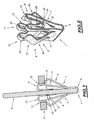
- FIGS. 1 and 2 show an elastic fastener which is designated by the general reference 1 and which makes it possible to fasten two parts to one another, these parts being formed for example by pieces of equipment of a motor vehicle.
- the first piece such as for example the piece 2 comprises a light designated by the general reference 4 in which is engaged the fastener 1.
- the second piece for example 3, is in turn hooked on the fastener 1.
- this elastic fastener has the general shape of a V having an intermediate portion designated by the general reference 5 from which extend the lateral wings designated by the general references 6 and 7 in these figures.
- lateral wings 6 and 7 of the fastener 1 are provided with means forming an outer tab, designated by the general references 8 and 9 in these figures and means forming an inner tab designated by the general references 10 and 11.
- the means forming the external tab of the fastener comprise, as can be seen more clearly in FIG. 2, a central external lug on each side of the fastener, respectively 8a and 9a, provided, for example, near its free end. , means in the form of elastic hook hard point crossing, designated by the general references 12 and 13 in these figures, to ensure the elastic attachment of the fastener on the edges of the light 4 of the first part 2.
- the means forming an inner lug designated by the general references 10 and 11 comprise in turn on each side of the fastener, two inner lugs respectively 14, 15 and 16, 17, disposed on either side of each outer lug 8a and 9a, respectively.
- these inner tabs comprise portions folded towards the inside of the fastener in the direction of the intermediate portion 5 thereof, these portions being for example in the form of bearing plates designated by the general references 18 and 19 in these figures, interconnecting the corresponding tabs on each side of the fastener.
- These support plates are provided with attachment means of the second part 3, these attachment means being for example formed by harpoons such as the harpoon 20 formed on one of the edges of the support plate 18 of connecting the inner tabs 14 and 15.
- folding zones of these internal tabs such as for example the zone designated by the general reference 21 in this figure, for the inner tab 14, are provided at the hook-shaped means 12, 13 of the outer tabs.
- this fastener can be made in one piece by cutting and deformation, for example a sheet blank.
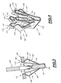
- One of the pieces is designated by the general reference 102 in these figures, while the other piece is designated by the general reference 103.
- the first piece such as for example the piece 102, comprises a light designated by the general reference 104, in which the clip 101 is engaged.
- the second piece for example 103, is hooked on the clip 101.
- this elastic fastener has the general shape of a V having an intermediate portion designated by the general reference 105 from which extend the lateral wings designated by the general references 106 and 107 in these figures.
- These lateral wings 106 and 107 of the fastener 101 are provided with means forming an outer tab, designated by the general references 108 and 109 in these figures and means forming an inner tab designated by the general references 110 and 111.
- the means forming the outer tab of the fastener comprise, as can be seen more clearly in FIG. 2, a central external tab on each side of the fastener, respectively 108a and 109a, provided, for example, near its free end. , means in the form of elastic hook to hard point crossing, designated by the general references 112 and 113 in these figures, to ensure the elastic attachment of the fastener on the edges of the light 104 of the first piece 102.
- the means forming an inner lug designated by the general references 110 and 111 comprise in turn on each side of the fastener, two inner lugs respectively 114, 115 and 116, 117, disposed on either side of each outer lug 108a and 109a, respectively.
- these inner tabs comprise inwardly folded portions of the fastener in the direction of the intermediate portion 105 thereof, these portions ending for example in the form of designated bearing plates. by the general references 118 and 119 in these figures, interconnecting the ends of the corresponding tabs on each side of the fastener.
- the front edges of these support plates form in fact hooking means of the second piece 103 insofar as these support plates are adapted to abut against abutment means complementary to this piece 103.
- the part 103 has a slot 120, against an edge of which abut the plates 118 and 119 of the fastener to ensure the locking in position of this clip and the room 103.
- the inner tabs may include hooking means of the second piece having different shapes from those illustrated.
- stop means of this piece different from an edge of a light thereof can also be envisaged.
- abutment means formed by raised parts such as for example a shoulder of this part, can also be envisaged.
- the folding zones of these internal tabs such as for example the zone designated by the general reference 121 in these figures, for the inner tab 114, are provided at the level of the hook-shaped means 112, 113, tabs external.
- this fastener can also be made in one piece by cutting and deformation, for example a sheet blank.
Landscapes
- Engineering & Computer Science (AREA)
- General Engineering & Computer Science (AREA)
- Mechanical Engineering (AREA)
- Clamps And Clips (AREA)
- Insertion Pins And Rivets (AREA)
- Table Equipment (AREA)
- Details Of Rigid Or Semi-Rigid Containers (AREA)
- Packages (AREA)
- Details Of Connecting Devices For Male And Female Coupling (AREA)
Claims (10)
- Federndes Verbindungsstück zur Befestigung von zwei Teilen aufeinander, welches die allgemeine Form eines V aufweist, mit einem Zwischenbereich (5; 105), von dem aus sich Seitenflügel (6, 7, 106, 107) erstrecken, die mit Außenanhängsel bildenden Mitteln (8, 9; 108, 109) versehen sind, welche Mittel in Form eines elastischen Hakens (12, 13; 112, 113) zum Überwinden einer harten Stelle und zum Einhaken des Verbindungsstücks (1; 101) an den Kanten eines Langlochs (4; 104) eines ersten Teils (2; 202) aufweisen, und mit Innenanhängsel bildenden Mitteln (10, 11; 110, 111), die mit Mitteln zum Einhaken (20; 118, 119) des zweiten Teils (3; 103) versehen sind, um dieses zweite Teil (3; 103) auf dem ersten (2; 202) zu befestigen, dadurch gekennzeichnet, dass die Innenanhängsel bildenden Mittel (10, 11; 110, 111) Bereiche (18, 19; 118, 119) aufweisen, die zum Inneren des Verbindungsstücks hin in Richtung dessen Zwischenbereichs (5; 505) übergeschlagen sind, dass die Einhakmittel (20; 118, 119) für das zweite Teil an diesen übergeschlagenen Bereichen der Innenanhängsel bildenden Mittel vorgesehen sind, und dass deren Umschlagbereiche (21; 121) auf der Höhe der hakenförmigen Mittel (12, 13; 112, 113) der Außenanhängsel bildenden Mittel (8, 9; 108, 109) vorgesehen sind.
- Verbindungsstück gemäß Anspruch 1, dadurch gekennzeichnet, dass jeder Seitenflügel (6, 7; 106, 107) des V-förmigen Verbindungsstücks (1; 101) ein mittleres Außenanhängsel (8a, 9a; 108a, 109a) aufweist, beidseits dessen ein seitliches Innenanhängsel (14, 15, 16, 17; 114, 115, 116, 117) vorgesehen ist.
- Verbindungsstück gemäß irgendeinem der Ansprüche 1 oder 2, dadurch gekennzeichnet, dass die Enden der seitlichen Innenanhängsel (14, 15, 16, 17) auf jeder Seite des Verbindungsstücks durch eine Auflageplatte (18, 19) verbunden sind, an deren Kanten die Einhakmittel (20) für das zweite Teil ausgebildet sind.
- Verbindungsstück gemäß Anspruch 3, dadurch gekennzeichnet, dass sich die Einhakmittel in Form von Gabelankern darstellen.
- Federndes Verbindungsstück gemäß Anspruch 1 oder 2, dadurch gekennzeichnet, dass die Einhakmittel (118, 119) für das zweite Teil von den Enden der übergeschlagenen Bereiche der Innenanhängsel bildenden Mittel gebildet und dafür eingerichtet sind in Auflage gegen Anschlagseinrichtungen (120) dieses zweiten Teils (103) zu gelangen.
- Verbindungsstück gemäß Anspruch 5, dadurch gekennzeichnet, dass die Enden der seitlichen Innenanhängsel (114, 115, 116, 117) auf jeder Seite des Verbindungsstücks durch eine Auflageplatte (118, 119) verbunden sind, deren Kanten die Einhakmittel für das zweite Teil bilden.
- Verbindungsstück gemäß irgendeinem der Ansprüche 5 oder 6, dadurch gekennzeichnet, dass die Anschlagsmittel des zweiten Teils (103) von dessen erhaben ausgebildeten Bereichen gebildet sind.
- Verbindungsstück gemäß Anspruch 7, dadurch gekennzeichnet, dass die Anschlagsmittel des zweiten Teils von einer Kante eines Langlochs (120) in diesem gebildet sind.
- Verbindungsstück gemäß Anspruch 7, dadurch gekennzeichnet, dass die Anschlagsmittel des zweiten Teils von einem Ansatz dieses Teils gebildet sind.
- Verbindungsstück gemäß irgendeinem der vorherigen Ansprüche, dadurch gekennzeichnet, dass es aus einem einzigen Stück anhand eines Blechplättchens durch dessen Zuschnitt und Verformung hergestellt ist.
Applications Claiming Priority (4)
| Application Number | Priority Date | Filing Date | Title |
|---|---|---|---|
| FR0306531A FR2855568B1 (fr) | 2003-05-28 | 2003-05-28 | Attache elastique pour la fixation de deux pieces l'une sur l'autre. |
| FR0306531 | 2003-05-28 | ||
| FR4000556 | 2004-01-21 | ||
| FR0400556A FR2865248B1 (fr) | 2004-01-21 | 2004-01-21 | Attache elastique pour la fixation de deux pieces l'une sur l'autre. |
Publications (3)
| Publication Number | Publication Date |
|---|---|
| EP1482184A2 EP1482184A2 (de) | 2004-12-01 |
| EP1482184A3 EP1482184A3 (de) | 2006-03-22 |
| EP1482184B1 true EP1482184B1 (de) | 2007-07-04 |
Family
ID=33133112
Family Applications (1)
| Application Number | Title | Priority Date | Filing Date |
|---|---|---|---|
| EP04291331A Active EP1482184B1 (de) | 2003-05-28 | 2004-05-26 | Federnder Verbinder zum Aufeinanderbefestigen zweier Werkstücke |
Country Status (7)
| Country | Link |
|---|---|
| US (1) | US7051408B2 (de) |
| EP (1) | EP1482184B1 (de) |
| AR (1) | AR044573A1 (de) |
| AT (1) | ATE366372T1 (de) |
| BR (1) | BRPI0402107B1 (de) |
| DE (1) | DE602004007326T2 (de) |
| ES (1) | ES2290644T3 (de) |
Families Citing this family (30)
| Publication number | Priority date | Publication date | Assignee | Title |
|---|---|---|---|---|
| US11577666B2 (en) * | 2012-05-21 | 2023-02-14 | Termax Llc | Arrowhead fastener clip with barbs |
| US8128145B2 (en) * | 2005-02-09 | 2012-03-06 | Termax Corporation | Tethered fastener apparatus and method |
| US9919674B2 (en) * | 2012-02-14 | 2018-03-20 | Termax Llc | Tethered fastener apparatus and method |
| FR2915539B1 (fr) * | 2007-04-26 | 2009-07-24 | Attax Sarl | Systeme de fixation de deux pieces l'une sur l'autre |
| FR2924187B1 (fr) * | 2007-11-26 | 2011-04-15 | Attax | Attache elastique pour la fixation de deux pieces l'une sur l'autre |
| CN102348900B (zh) | 2009-03-11 | 2013-07-17 | 伊利诺斯工具制品有限公司 | 紧固装置 |
| ES2383871B1 (es) * | 2010-02-16 | 2013-05-07 | Illinois Tool Works Inc. | Clip rápido de fijación. |
| DE102011114030B4 (de) * | 2011-09-08 | 2019-03-28 | Audi Ag | Federbefestigungsclip |
| CN104246242B (zh) * | 2012-04-02 | 2016-05-04 | 百乐仕株式会社 | 夹子以及夹子装置 |
| KR101730945B1 (ko) * | 2012-12-28 | 2017-04-27 | 요코하마 고무 가부시키가이샤 | 공기입 타이어 |
| CN104870208B (zh) * | 2012-12-28 | 2017-03-08 | 横滨橡胶株式会社 | 充气轮胎 |
| US9657759B2 (en) | 2014-09-10 | 2017-05-23 | Newfrey Llc | U-based fastener with improved rib attachment |
| US9649993B1 (en) * | 2015-08-20 | 2017-05-16 | Termax Corporation | One step assembly fastener clip |
| US10006479B2 (en) * | 2015-08-20 | 2018-06-26 | Termax Llc | Fastener clip assembly with funnel guide |
| US10340166B2 (en) * | 2015-11-22 | 2019-07-02 | George Xinsheng Guo | Substrates handling in a deposition system |
| US10384758B2 (en) * | 2016-01-26 | 2019-08-20 | The Boeing Company | Sandwich panel assembly and method |
| CN108884849B (zh) * | 2016-03-22 | 2021-02-12 | 伊利诺斯工具制品有限公司 | 紧固夹 |
| DE102016012955A1 (de) | 2016-10-29 | 2018-05-03 | Audi Ag | Federbefestigungsclip |
| CN111051710B (zh) | 2017-07-11 | 2022-03-08 | 伊利诺斯工具制品有限公司 | 边缘保护器 |
| US10704577B2 (en) | 2017-10-18 | 2020-07-07 | Newfrey Llc | U-base fastener with folded barb |
| US10894516B2 (en) | 2017-10-18 | 2021-01-19 | Newfrey Llc | U-base fastener with folded barb and multiple spring arms |
| US10973321B2 (en) | 2018-09-04 | 2021-04-13 | Steelcase Inc. | Workspace system and components and method for the use thereof |
| FR3087859B1 (fr) * | 2018-10-31 | 2020-10-16 | Faurecia Interieur Ind | Attache et ensemble de fixation comprenant une telle attache |
| DE102018127519A1 (de) * | 2018-11-05 | 2020-05-07 | Illinois Tool Works Inc. | Befestigungsclip zur Befestigung eines Anbauteils an einer Trägerkante |
| US11149774B2 (en) | 2019-10-03 | 2021-10-19 | Newfrey Llc | Bathtub fastener assembly |
| US10968931B1 (en) | 2019-10-17 | 2021-04-06 | Newfrey Llc | Dual component sealing fastener and coupling assembly including same |
| CN114930037A (zh) | 2020-01-17 | 2022-08-19 | 伊利诺斯工具制品有限公司 | 金属保持夹 |
| USD934063S1 (en) | 2020-01-20 | 2021-10-26 | Illinois Tool Works Inc. | Fastening clip |
| US11744391B2 (en) * | 2020-04-21 | 2023-09-05 | Concept Plastics Limited | Hook for hanging basket |
| US11746812B2 (en) | 2021-05-12 | 2023-09-05 | Newfrey Llc | Dual component sealing fastener and coupling assembly including same |
Family Cites Families (12)
| Publication number | Priority date | Publication date | Assignee | Title |
|---|---|---|---|---|
| US4402118A (en) * | 1981-09-28 | 1983-09-06 | Usm Corporation | Clip for securing a panel to a support |
| DE3245056A1 (de) * | 1982-12-06 | 1984-06-07 | USM Corp., Farmington, Conn. | Elastische klemme |
| DE19702429A1 (de) * | 1997-01-24 | 1998-07-30 | Raymond A & Cie | Klammersystem zur Befestigung eines Anbauteils an einem Trägerteil |
| JP3463272B2 (ja) | 1997-07-01 | 2003-11-05 | 本田技研工業株式会社 | 部品取付用クリップ |
| US6101686A (en) * | 1998-03-17 | 2000-08-15 | Daimlerchrysler Corporation | Interior trim spring clip |
| US6279207B1 (en) * | 1999-02-01 | 2001-08-28 | Wtpa, Incorporated | Fasteners with increased holding power |
| US6353981B1 (en) * | 1999-02-25 | 2002-03-12 | Termax Corporation | Multi-engagement spring fastener |
| US6141837A (en) * | 1999-02-26 | 2000-11-07 | Wisniewski; David M. | EDIAS clip for securing an interior molding to a vehicle frame |
| US7120971B2 (en) * | 2001-03-02 | 2006-10-17 | Newfrey Llc | Low insertion effort u-base retainer |
| US6718599B2 (en) * | 2001-06-25 | 2004-04-13 | Termax Corporation | Spring fastener with ergonomically balanced removal to insertion force ratio |
| US6691380B2 (en) * | 2001-07-31 | 2004-02-17 | Eustathios Vassiliou Revocable Trust | Fasteners of increased holding power |
| JP2005527752A (ja) | 2002-05-28 | 2005-09-15 | ニューフレイ リミテッド ライアビリティ カンパニー | 弾性クリップ式ファスナ及びその製造方法 |
-
2004
- 2004-05-26 DE DE602004007326T patent/DE602004007326T2/de active Active
- 2004-05-26 AT AT04291331T patent/ATE366372T1/de not_active IP Right Cessation
- 2004-05-26 ES ES04291331T patent/ES2290644T3/es active Active
- 2004-05-26 EP EP04291331A patent/EP1482184B1/de active Active
- 2004-05-26 BR BRPI0402107-0A patent/BRPI0402107B1/pt not_active IP Right Cessation
- 2004-05-27 US US10/854,760 patent/US7051408B2/en active Active
- 2004-05-28 AR ARP040101859A patent/AR044573A1/es not_active Application Discontinuation
Also Published As
| Publication number | Publication date |
|---|---|
| DE602004007326T2 (de) | 2008-03-06 |
| EP1482184A2 (de) | 2004-12-01 |
| DE602004007326D1 (de) | 2007-08-16 |
| ES2290644T3 (es) | 2008-02-16 |
| US20050000063A1 (en) | 2005-01-06 |
| BRPI0402107A (pt) | 2005-05-17 |
| ATE366372T1 (de) | 2007-07-15 |
| EP1482184A3 (de) | 2006-03-22 |
| US7051408B2 (en) | 2006-05-30 |
| AR044573A1 (es) | 2005-09-21 |
| BRPI0402107B1 (pt) | 2015-06-30 |
Similar Documents
| Publication | Publication Date | Title |
|---|---|---|
| EP1482184B1 (de) | Federnder Verbinder zum Aufeinanderbefestigen zweier Werkstücke | |
| EP1985871B1 (de) | Befestigungssystem von zwei Teilen aufeinander | |
| EP1557572B1 (de) | Klipp zur gegenseitigen Befestigung von zwei Teilen | |
| EP1760328B1 (de) | Elastisches Verbindungselement zur Befestigung von zwei Teilen aufeinander | |
| EP3561360B1 (de) | Spannsystem mit herunterklappbaren spannbacken für den anschluss von rohren | |
| EP2220384B1 (de) | Federklemme zum aneinanderbefestigen von zwei komponenten | |
| EP1728687B1 (de) | Anordnung zur Montage einer Zierleiste an einem Kraftfahrzeug Karosserieteil | |
| EP1722111B1 (de) | Befestigungselement zur Befestigung eines Metallprofils auf einem Träger | |
| FR3049533A1 (fr) | Dispositif de maintien d'au moins un objet dans un espace interieur de vehicule automobile | |
| EP1249653B1 (de) | Kabelrinnenelement | |
| FR2865248A1 (fr) | Attache elastique pour la fixation de deux pieces l'une sur l'autre. | |
| EP2867098B1 (de) | Halterung zum fügen eines stossfängerhaut an eines fahrzeugbauteil | |
| EP0569297A1 (de) | Halterung für mehrere Leitungen, Kabel oder ähnliches | |
| EP2006553A1 (de) | Anordnung zum Befestigen eines Teils auf einem anderen | |
| EP3442852B1 (de) | Anordnung einer abschirmung und eines karosserieelements eines kraftfahrzeugs, insbesondere eines karosserieelements aus blech | |
| EP2177775B1 (de) | Anlage zum Zusammenbauen von zwei Teilen, wie beispielsweise zwei Platten, mittels einer Schraubvorrichtung mit Verankerungsmutter | |
| FR2794501A1 (fr) | Ecrou comportant des moyens de fixation sur un support | |
| FR2855568A1 (fr) | Attache elastique pour la fixation de deux pieces l'une sur l'autre. | |
| EP0169747A1 (de) | Stossdämpfer für Fahrzeug | |
| EP2755841A2 (de) | Kühlungsanordnung für ein kraftfahrzeug | |
| FR2899655A1 (fr) | Attache elastique pour la fixation de deux pieces. | |
| FR2899656A1 (fr) | Attache elastique de fixation de deux pieces l'une sur l'autre. | |
| EP0820915A1 (de) | Befestigungseinrichtung einer Fahrzeuglenkradnabe auf einem Lenksäulenende | |
| EP0318371B1 (de) | In eine Verbindungsfuge einsetzbare elastische Klammer für die automatische und lösbare Befestigung von verschiedenen Gegenständen, insbesondere Fugenleisten | |
| EP0685655A1 (de) | Elastische Befestigungsklammer |
Legal Events
| Date | Code | Title | Description |
|---|---|---|---|
| PUAI | Public reference made under article 153(3) epc to a published international application that has entered the european phase |
Free format text: ORIGINAL CODE: 0009012 |
|
| AK | Designated contracting states |
Kind code of ref document: A2 Designated state(s): AT BE BG CH CY CZ DE DK EE ES FI FR GB GR HU IE IT LI LU MC NL PL PT RO SE SI SK TR |
|
| AX | Request for extension of the european patent |
Extension state: AL HR LT LV MK |
|
| PUAL | Search report despatched |
Free format text: ORIGINAL CODE: 0009013 |
|
| AK | Designated contracting states |
Kind code of ref document: A3 Designated state(s): AT BE BG CH CY CZ DE DK EE ES FI FR GB GR HU IE IT LI LU MC NL PL PT RO SE SI SK TR |
|
| AX | Request for extension of the european patent |
Extension state: AL HR LT LV MK |
|
| 17P | Request for examination filed |
Effective date: 20060914 |
|
| GRAP | Despatch of communication of intention to grant a patent |
Free format text: ORIGINAL CODE: EPIDOSNIGR1 |
|
| AKX | Designation fees paid |
Designated state(s): AT BE BG CH CY CZ DE DK EE ES FI FR GB GR HU IE IT LI LU MC NL PL PT RO SE SI SK TR |
|
| GRAS | Grant fee paid |
Free format text: ORIGINAL CODE: EPIDOSNIGR3 |
|
| GRAA | (expected) grant |
Free format text: ORIGINAL CODE: 0009210 |
|
| AK | Designated contracting states |
Kind code of ref document: B1 Designated state(s): AT BE BG CH CY CZ DE DK EE ES FI FR GB GR HU IE IT LI LU MC NL PL PT RO SE SI SK TR |
|
| REG | Reference to a national code |
Ref country code: GB Ref legal event code: FG4D Free format text: NOT ENGLISH |
|
| REG | Reference to a national code |
Ref country code: CH Ref legal event code: EP |
|
| REG | Reference to a national code |
Ref country code: IE Ref legal event code: FG4D Free format text: LANGUAGE OF EP DOCUMENT: FRENCH |
|
| REF | Corresponds to: |
Ref document number: 602004007326 Country of ref document: DE Date of ref document: 20070816 Kind code of ref document: P |
|
| GBT | Gb: translation of ep patent filed (gb section 77(6)(a)/1977) |
Effective date: 20071001 |
|
| NLV1 | Nl: lapsed or annulled due to failure to fulfill the requirements of art. 29p and 29m of the patents act | ||
| PG25 | Lapsed in a contracting state [announced via postgrant information from national office to epo] |
Ref country code: FI Free format text: LAPSE BECAUSE OF FAILURE TO SUBMIT A TRANSLATION OF THE DESCRIPTION OR TO PAY THE FEE WITHIN THE PRESCRIBED TIME-LIMIT Effective date: 20070704 Ref country code: SI Free format text: LAPSE BECAUSE OF FAILURE TO SUBMIT A TRANSLATION OF THE DESCRIPTION OR TO PAY THE FEE WITHIN THE PRESCRIBED TIME-LIMIT Effective date: 20070704 Ref country code: PT Free format text: LAPSE BECAUSE OF FAILURE TO SUBMIT A TRANSLATION OF THE DESCRIPTION OR TO PAY THE FEE WITHIN THE PRESCRIBED TIME-LIMIT Effective date: 20071204 Ref country code: NL Free format text: LAPSE BECAUSE OF FAILURE TO SUBMIT A TRANSLATION OF THE DESCRIPTION OR TO PAY THE FEE WITHIN THE PRESCRIBED TIME-LIMIT Effective date: 20070704 Ref country code: BG Free format text: LAPSE BECAUSE OF FAILURE TO SUBMIT A TRANSLATION OF THE DESCRIPTION OR TO PAY THE FEE WITHIN THE PRESCRIBED TIME-LIMIT Effective date: 20071004 |
|
| REG | Reference to a national code |
Ref country code: ES Ref legal event code: FG2A Ref document number: 2290644 Country of ref document: ES Kind code of ref document: T3 |
|
| PG25 | Lapsed in a contracting state [announced via postgrant information from national office to epo] |
Ref country code: AT Free format text: LAPSE BECAUSE OF FAILURE TO SUBMIT A TRANSLATION OF THE DESCRIPTION OR TO PAY THE FEE WITHIN THE PRESCRIBED TIME-LIMIT Effective date: 20070704 Ref country code: PL Free format text: LAPSE BECAUSE OF FAILURE TO SUBMIT A TRANSLATION OF THE DESCRIPTION OR TO PAY THE FEE WITHIN THE PRESCRIBED TIME-LIMIT Effective date: 20070704 |
|
| PG25 | Lapsed in a contracting state [announced via postgrant information from national office to epo] |
Ref country code: GR Free format text: LAPSE BECAUSE OF FAILURE TO SUBMIT A TRANSLATION OF THE DESCRIPTION OR TO PAY THE FEE WITHIN THE PRESCRIBED TIME-LIMIT Effective date: 20071005 Ref country code: DK Free format text: LAPSE BECAUSE OF FAILURE TO SUBMIT A TRANSLATION OF THE DESCRIPTION OR TO PAY THE FEE WITHIN THE PRESCRIBED TIME-LIMIT Effective date: 20070704 |
|
| PLBE | No opposition filed within time limit |
Free format text: ORIGINAL CODE: 0009261 |
|
| STAA | Information on the status of an ep patent application or granted ep patent |
Free format text: STATUS: NO OPPOSITION FILED WITHIN TIME LIMIT |
|
| PG25 | Lapsed in a contracting state [announced via postgrant information from national office to epo] |
Ref country code: SK Free format text: LAPSE BECAUSE OF FAILURE TO SUBMIT A TRANSLATION OF THE DESCRIPTION OR TO PAY THE FEE WITHIN THE PRESCRIBED TIME-LIMIT Effective date: 20070704 Ref country code: CZ Free format text: LAPSE BECAUSE OF FAILURE TO SUBMIT A TRANSLATION OF THE DESCRIPTION OR TO PAY THE FEE WITHIN THE PRESCRIBED TIME-LIMIT Effective date: 20070704 |
|
| 26N | No opposition filed |
Effective date: 20080407 |
|
| PG25 | Lapsed in a contracting state [announced via postgrant information from national office to epo] |
Ref country code: SE Free format text: LAPSE BECAUSE OF FAILURE TO SUBMIT A TRANSLATION OF THE DESCRIPTION OR TO PAY THE FEE WITHIN THE PRESCRIBED TIME-LIMIT Effective date: 20071004 Ref country code: RO Free format text: LAPSE BECAUSE OF FAILURE TO SUBMIT A TRANSLATION OF THE DESCRIPTION OR TO PAY THE FEE WITHIN THE PRESCRIBED TIME-LIMIT Effective date: 20070704 |
|
| PG25 | Lapsed in a contracting state [announced via postgrant information from national office to epo] |
Ref country code: EE Free format text: LAPSE BECAUSE OF FAILURE TO SUBMIT A TRANSLATION OF THE DESCRIPTION OR TO PAY THE FEE WITHIN THE PRESCRIBED TIME-LIMIT Effective date: 20070704 |
|
| PG25 | Lapsed in a contracting state [announced via postgrant information from national office to epo] |
Ref country code: CY Free format text: LAPSE BECAUSE OF FAILURE TO SUBMIT A TRANSLATION OF THE DESCRIPTION OR TO PAY THE FEE WITHIN THE PRESCRIBED TIME-LIMIT Effective date: 20070704 |
|
| PG25 | Lapsed in a contracting state [announced via postgrant information from national office to epo] |
Ref country code: HU Free format text: LAPSE BECAUSE OF FAILURE TO SUBMIT A TRANSLATION OF THE DESCRIPTION OR TO PAY THE FEE WITHIN THE PRESCRIBED TIME-LIMIT Effective date: 20080105 |
|
| PG25 | Lapsed in a contracting state [announced via postgrant information from national office to epo] |
Ref country code: TR Free format text: LAPSE BECAUSE OF FAILURE TO SUBMIT A TRANSLATION OF THE DESCRIPTION OR TO PAY THE FEE WITHIN THE PRESCRIBED TIME-LIMIT Effective date: 20070704 |
|
| REG | Reference to a national code |
Ref country code: FR Ref legal event code: PLFP Year of fee payment: 13 |
|
| REG | Reference to a national code |
Ref country code: FR Ref legal event code: PLFP Year of fee payment: 14 |
|
| PGFP | Annual fee paid to national office [announced via postgrant information from national office to epo] |
Ref country code: IE Payment date: 20170502 Year of fee payment: 14 Ref country code: MC Payment date: 20170419 Year of fee payment: 14 |
|
| PGFP | Annual fee paid to national office [announced via postgrant information from national office to epo] |
Ref country code: BE Payment date: 20170531 Year of fee payment: 14 Ref country code: LU Payment date: 20170414 Year of fee payment: 14 |
|
| REG | Reference to a national code |
Ref country code: FR Ref legal event code: PLFP Year of fee payment: 15 |
|
| REG | Reference to a national code |
Ref country code: CH Ref legal event code: PL |
|
| REG | Reference to a national code |
Ref country code: BE Ref legal event code: MM Effective date: 20180531 |
|
| PG25 | Lapsed in a contracting state [announced via postgrant information from national office to epo] |
Ref country code: MC Free format text: LAPSE BECAUSE OF NON-PAYMENT OF DUE FEES Effective date: 20180601 |
|
| REG | Reference to a national code |
Ref country code: IE Ref legal event code: MM4A |
|
| PG25 | Lapsed in a contracting state [announced via postgrant information from national office to epo] |
Ref country code: LI Free format text: LAPSE BECAUSE OF NON-PAYMENT OF DUE FEES Effective date: 20180531 Ref country code: CH Free format text: LAPSE BECAUSE OF NON-PAYMENT OF DUE FEES Effective date: 20180531 |
|
| PG25 | Lapsed in a contracting state [announced via postgrant information from national office to epo] |
Ref country code: LU Free format text: LAPSE BECAUSE OF NON-PAYMENT OF DUE FEES Effective date: 20180526 |
|
| PG25 | Lapsed in a contracting state [announced via postgrant information from national office to epo] |
Ref country code: IE Free format text: LAPSE BECAUSE OF NON-PAYMENT OF DUE FEES Effective date: 20180526 |
|
| PG25 | Lapsed in a contracting state [announced via postgrant information from national office to epo] |
Ref country code: BE Free format text: LAPSE BECAUSE OF NON-PAYMENT OF DUE FEES Effective date: 20180531 |
|
| REG | Reference to a national code |
Ref country code: FR Ref legal event code: PLFP Year of fee payment: 20 |
|
| PGFP | Annual fee paid to national office [announced via postgrant information from national office to epo] |
Ref country code: IT Payment date: 20230517 Year of fee payment: 20 Ref country code: FR Payment date: 20230412 Year of fee payment: 20 Ref country code: ES Payment date: 20230607 Year of fee payment: 20 Ref country code: DE Payment date: 20230510 Year of fee payment: 20 |
|
| PGFP | Annual fee paid to national office [announced via postgrant information from national office to epo] |
Ref country code: GB Payment date: 20230519 Year of fee payment: 20 |