EP1479954B1 - Öldynamisches Druck- und Schneidwerkzeug - Google Patents
Öldynamisches Druck- und Schneidwerkzeug Download PDFInfo
- Publication number
- EP1479954B1 EP1479954B1 EP04010652A EP04010652A EP1479954B1 EP 1479954 B1 EP1479954 B1 EP 1479954B1 EP 04010652 A EP04010652 A EP 04010652A EP 04010652 A EP04010652 A EP 04010652A EP 1479954 B1 EP1479954 B1 EP 1479954B1
- Authority
- EP
- European Patent Office
- Prior art keywords
- handle
- oil
- inner grip
- hydraulic
- pivotable
- Prior art date
- Legal status (The legal status is an assumption and is not a legal conclusion. Google has not performed a legal analysis and makes no representation as to the accuracy of the status listed.)
- Expired - Lifetime
Links
- 238000005520 cutting process Methods 0.000 title claims description 13
- 239000000463 material Substances 0.000 claims description 2
- 230000037431 insertion Effects 0.000 claims 1
- 238000003780 insertion Methods 0.000 claims 1
- 238000006073 displacement reaction Methods 0.000 abstract description 13
- 230000007246 mechanism Effects 0.000 description 9
- 239000000725 suspension Substances 0.000 description 8
- 238000012423 maintenance Methods 0.000 description 5
- 239000012811 non-conductive material Substances 0.000 description 5
- 238000005086 pumping Methods 0.000 description 4
- 230000000903 blocking effect Effects 0.000 description 3
- 230000006835 compression Effects 0.000 description 3
- 238000007906 compression Methods 0.000 description 3
- RYGMFSIKBFXOCR-UHFFFAOYSA-N Copper Chemical compound [Cu] RYGMFSIKBFXOCR-UHFFFAOYSA-N 0.000 description 1
- 229910052782 aluminium Inorganic materials 0.000 description 1
- XAGFODPZIPBFFR-UHFFFAOYSA-N aluminium Chemical compound [Al] XAGFODPZIPBFFR-UHFFFAOYSA-N 0.000 description 1
- 238000011109 contamination Methods 0.000 description 1
- 229910052802 copper Inorganic materials 0.000 description 1
- 239000010949 copper Substances 0.000 description 1
- 229910052751 metal Inorganic materials 0.000 description 1
- 230000000750 progressive effect Effects 0.000 description 1
- 230000003014 reinforcing effect Effects 0.000 description 1
- 230000000717 retained effect Effects 0.000 description 1
Images

Classifications
-
- B—PERFORMING OPERATIONS; TRANSPORTING
- B23—MACHINE TOOLS; METAL-WORKING NOT OTHERWISE PROVIDED FOR
- B23D—PLANING; SLOTTING; SHEARING; BROACHING; SAWING; FILING; SCRAPING; LIKE OPERATIONS FOR WORKING METAL BY REMOVING MATERIAL, NOT OTHERWISE PROVIDED FOR
- B23D29/00—Hand-held metal-shearing or metal-cutting devices
- B23D29/002—Hand-held metal-shearing or metal-cutting devices for cutting wire or the like
-
- B—PERFORMING OPERATIONS; TRANSPORTING
- B23—MACHINE TOOLS; METAL-WORKING NOT OTHERWISE PROVIDED FOR
- B23D—PLANING; SLOTTING; SHEARING; BROACHING; SAWING; FILING; SCRAPING; LIKE OPERATIONS FOR WORKING METAL BY REMOVING MATERIAL, NOT OTHERWISE PROVIDED FOR
- B23D15/00—Shearing machines or shearing devices cutting by blades which move parallel to themselves
- B23D15/12—Shearing machines or shearing devices cutting by blades which move parallel to themselves characterised by drives or gearings therefor
- B23D15/14—Shearing machines or shearing devices cutting by blades which move parallel to themselves characterised by drives or gearings therefor actuated by fluid or gas pressure
-
- B—PERFORMING OPERATIONS; TRANSPORTING
- B25—HAND TOOLS; PORTABLE POWER-DRIVEN TOOLS; MANIPULATORS
- B25B—TOOLS OR BENCH DEVICES NOT OTHERWISE PROVIDED FOR, FOR FASTENING, CONNECTING, DISENGAGING OR HOLDING
- B25B27/00—Hand tools, specially adapted for fitting together or separating parts or objects whether or not involving some deformation, not otherwise provided for
- B25B27/14—Hand tools, specially adapted for fitting together or separating parts or objects whether or not involving some deformation, not otherwise provided for for assembling objects other than by press fit or detaching same
- B25B27/146—Clip clamping hand tools
-
- F—MECHANICAL ENGINEERING; LIGHTING; HEATING; WEAPONS; BLASTING
- F16—ENGINEERING ELEMENTS AND UNITS; GENERAL MEASURES FOR PRODUCING AND MAINTAINING EFFECTIVE FUNCTIONING OF MACHINES OR INSTALLATIONS; THERMAL INSULATION IN GENERAL
- F16K—VALVES; TAPS; COCKS; ACTUATING-FLOATS; DEVICES FOR VENTING OR AERATING
- F16K15/00—Check valves
- F16K15/18—Check valves with actuating mechanism; Combined check valves and actuated valves
- F16K15/182—Check valves with actuating mechanism; Combined check valves and actuated valves with actuating mechanism
- F16K15/1823—Check valves with actuating mechanism; Combined check valves and actuated valves with actuating mechanism for ball check valves
-
- H—ELECTRICITY
- H01—ELECTRIC ELEMENTS
- H01R—ELECTRICALLY-CONDUCTIVE CONNECTIONS; STRUCTURAL ASSOCIATIONS OF A PLURALITY OF MUTUALLY-INSULATED ELECTRICAL CONNECTING ELEMENTS; COUPLING DEVICES; CURRENT COLLECTORS
- H01R43/00—Apparatus or processes specially adapted for manufacturing, assembling, maintaining, or repairing of line connectors or current collectors or for joining electric conductors
- H01R43/04—Apparatus or processes specially adapted for manufacturing, assembling, maintaining, or repairing of line connectors or current collectors or for joining electric conductors for forming connections by deformation, e.g. crimping tool
- H01R43/042—Hand tools for crimping
- H01R43/0427—Hand tools for crimping fluid actuated hand crimping tools
Definitions
- the known oleodynamic tools consist essentially of a pump body which is fixedly connected to a handle, from a second handle for the actuation of the pump which is pivotally mounted on the same pump body and a front approach to the pump body for the use of replaceable printing or cutting heads.
- the tools must be provided with a drain valve to allow, as a result of the execution of a pressure or cutting operation, the opening of the tool and further comprise a locking mechanism to prevent the spreading of the movable handle by the action of acting on the pump piston return spring.
- the blocking of the pivotable handle in the closed position takes place on the known tools by means of a small belt which is attached to the end of one of the handles and can be attached with the handles closed at the end of the other handle, whereby the spreading of the handles is prevented; also a lever or handle operated suspension element which is provided on the handle can prevent spreading.
- the invention has as its object to provide an oil dynamic tool of the type mentioned above which a comfortable operation of the drain valve in any position of the pivoting handle and the locking of the closed position of the pivoting handle, without the operation allows specific locking mechanisms, which further can be actuated with only one hand to the rapid adjustment movement of the tools to achieve the workpiece with maintenance and repair friendliness and optimal protection against unwanted electrical contacts is offered.
- the pivoting handle whether it is the operation of the drain valve, as well as the blocking of the closed position of the handle is assigned;
- the invention proposes the attachment of shells of non-conductive material, which are easily removable in the case of maintenance and / or repair and, in the case of damage, interchangeable with the strictest safety standards.
- the pivotable handle is rotatably mounted on the body of the oil pump according to its longitudinal axis wherein an axial displacement is generated by the rotation, wherein a direction of rotation is used to act on the drain valve and the other opposite direction of rotation is used to act on a Einhnatureorgan.
- the locking of the handle in the closed position is done by turning the handle in the opposite direction whereby a suspension element, after taking the closed position of the handle, is brought into the locked position.
- rotatable about its longitudinal axis storage of the handle on the receiving element is provided, at the end of the handle a rotary and displacement element is provided which is in screw connection with the receiving element, by rotating the said rotation - And displacement element is thus an axial displacement of the rotary and Moving element reaches even which is coaxially attached to the end of the handle.
- the front end of said rotary and translating element according to the invention is suitable for axial feed, as a result of rotation of the handle e.g. to the right to act on mechanical elements which are in contact with each other or are connected to each other and are loaded by at least one compression spring, wherein said spring is loaded with pressure and the drain valve is opened.
- the mounted at the end of the handle rotary and displacement element which has a threaded portion acts, by means of the two ends of the diameter of this element projecting cross pin and due to rotation in the opposite direction and thus due to displacement (retraction) on a suspension element whose end, in the closed position the handle engages in a recess on the pump housing to close the closed position of the handle close to the, with the pump housing firmly connected handle.
- the handles are preferably made of non-conductive material, the region of the end portions near the pump body is in any case according to the invention provided with a non-conductive connection and reinforcing sleeve, wherein the non-conductive sleeve on the pivotable handle for the Attachment of an inner handle is used which can be easily grasped with one hand together with the corresponding portion of the immovable handle to fast pumping movements for the purpose of a rapid approach of the tools to reach the connecting parts.
- the shape of this handle may be variously, bow-shaped or annular and although closed or open, be integral with the non-conductive sleeve or attached to this, or even directly on the handle.
- the handle has the shape of an open strap or ring
- the connection to the handle or to the sleeve consists of only one connecting leg.
- the invention further does not exclude that the inner handle extends over a part or the entire length of the handle or that this handle is made of flexible material or is a belt or a cord.
- the pump body can be covered by two lateral shells, the edges of which overlap one another with a width defined by the safety standards, and are retained in the assembled position on the face side and on the back by a ring of non-conductive material.
- the front ring also forms a collar which covers the approach area of the oil-dynamic pressure or cutting tool heads while the rear ring holds the assembled, the front portion of the non-conductive cover of the immovable handle cross-shells firmly.
- the two attached laterally to the pump body shells according to the invention also form part of the non-conductive cover of the storage area of the pivotable handle by these form the shape of a spherical cap which is determined by the position of the bearing pin of the pivoting handle.
- This portion of the insulating cover is partially covered by a shell which is attached to the front end of the non-conductive sleeve of the pivotable handle.
- This shell is on the side, coaxial with the axis of rotation of the pivotable handle, from the side of the pump body mounted non-conductive shells, protruding pins, snapped and held by pins which protrude from the non-conductive sleeve of the pivoting handle near the storage area, whereby a complete articulated cover of the entire storage area is achieved.
- the attachment of the non-conductive shells by snapping and by mutual intervention according to the invention allow quick and easy assembly and disassembly and thus easy replacement, and facilitate the maintenance and repair of the tool.
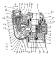
- the Fig. 1 shows a side view of the invention ildynamic pressure and cutting tool with closed handles.
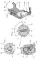
- the Fig. 2 shows the view from the left of the in Fig. 1 illustrated tool.
- the Fig. 3 shows the cross section through the pump housing according to a sectional plane through the axes of the handles, by the mounting of the pivotable handle, by the actuating mechanism of the drain valve and by the locking mechanism of the pivotable handle.
- the Fig. 4 is a sectional view according to the in Fig. 3 shown section plane IV-IV which passes through the suspension element of the pivotable handle in the closed position.
- the Fig. 5 is a sectional view according to the in Fig. 3 shown section plane VV which passes through the actuating mechanism of the suspension element of the pivotable handle in the closed position.
- the Fig. 6 is a sectional view according to the in Fig. 3 shown section plane VI-VI which extends through the mechanism for the definition of the different operating positions of the pivotable handle.
- the Fig. 7 shows a sectional view of the detail of the joint of the non-conductive cover which is attached to the tool body in the region between the two handles in a spread position.
- the oleodynamic pressure and cutting tool consists essentially of a body 2 which is formed by the housing 11 for a hydraulic pump and the corresponding valves 10; from lines for the flow of oil, from actuators, from a handle 3 which is fixedly connected to the housing 11 and a handle 3a which pivotally mounted on the housing 3 3d 6 is.
- the housing 11 is provided on the front side with a projection for the use of various rotatable 1a oil-dynamic printing or cutting heads 1.
- the pivotable handle 3a is fixed by means of transverse pin 4f to a tubular extension 4a of a rotary and displacement element 4 which is rotatably mounted on a bearing element 5 which in turn is mounted pivotably 3d by means of transverse pin 6 on the housing 11 of the pump.
- the same element 4 is provided with a bolt with roller 3c which acts on pivoting 3d on a sliding 12a plunger 12 which in turn acts on the equipped with return spring 13a piston 13 of the pump.
- the rotating and displacing element 4 has a bolt-shaped projection 4d with a conical end 4d at the end and is rotatably mounted in a receptacle 5a on the element 5.
- the bolt-shaped projection 4c is continued in a threaded part 4b on which a larger diameter part with transverse bore connects in which two balls 19 are received which are pressed by an interposed spring 20 to the outside, said balls 19 snap into corresponding spherical cap-shaped seats or grooves which in the tubular end portion 5b are provided for receiving the bearing element 5.
- the spherical cap-shaped or groove-shaped seats define three positions of the rotation 3r of the pivoting handle 3a with respect to the bearing member 5: a middle position P for pumping, a position R for operating the drain valve 10 and a position B for locking the pivotal handle 3a in closed position Position.
- the invention proposes the use of handles 3, 3a exclusively of non-conductive material and the complete lining of the housing 11 of the pump, together with the mounting of the pivotable handle 3a and all mechanisms for the actuation of the drain valve and for the lock of the handle 3a in the closed position, by means of laterally easily replaceable plastic covers, in full compliance with the applicable safety standards, before.
- On the housing 11, according to the invention according to the direction of the axis of rotation 6 of the pivoting handle 3a, two lateral shells 14, 14a attached, these cover themselves along the connection area and are frontally by placing a ring 15 which also the approach of the attached interchangeable printing or cutting tool heads 1 covering and a rear ring 16 attached from non-conductive material.
- the shells 14, 14a form in the region of the pivot bearing 6 of the pivotable handle 3a a ball tip 14c which is partially covered by a shell 17 which is snapped at the front end of the non-conductive sleeve 18a of the handle 3a and held by the sleeve projecting from this pin 18b which engages in corresponding holes on the shell 17.
- the shell 17 has further in, corresponding to the axis of the bearing 6 of the handle 3a Area, lateral holes in which pins 14 b engage which, always in the axis of the storage 6 corresponding area, laterally project from the side shells 14 and 14 a.
- the shell 17 in the region of the projection 14c of the lateral shells 14, 14a has a region which covers the projection 14c and that the projection 14c and also the covering region of the shell 17 have a curvature centered on the axis of rotation of the bearing 6, becomes a articulated connection between the, attached to the housing 11, shells 14, 14a which form the projection 14c and, attached to the pivotable handle 3a, shell 17 is formed.
- the invention does not exclude that the articulated guidance of the non-conductive shell 17 on the ball-shaped projection 14c, 14d by means of circular arc-shaped grooves whose center is located on the axis of rotation of the bearing 6 and in which corresponding webs or projections, takes place.
- an insulating cover in the region of the joint between the two handle levers 3, 3a, attached to the handle 3a non-conductive sleeve 18a is provided with arcuate parallel grooves 18c within which laterally a curved Element 17a is slidably inserted which is suitable to guarantee the metallic elements in the interior of the spherical cap-shaped projection 14c, 14d of the two lateral shells 14, 14a, in any position of the pivotable handle 3a, always the cover according to safety regulations.
Landscapes
- Engineering & Computer Science (AREA)
- Mechanical Engineering (AREA)
- General Engineering & Computer Science (AREA)
- Manufacturing & Machinery (AREA)
- Jigs For Machine Tools (AREA)
- Earth Drilling (AREA)
- Shearing Machines (AREA)
- Lubricants (AREA)
- Press Drives And Press Lines (AREA)
- Details Of Reciprocating Pumps (AREA)
Description
- Es sind öldynamische Handwerkzeuge bekannt welche in der Anlagentechnik für das Zusammendrücken von Kabelschuhen und Kabelverbindungen oder für das Durchtrennen von Kupfer- oder Aluminiumkabeln eingesetzt werden.
- Die bekannten öldynamischen Werkzeuge bestehen wesentlich aus einem Pumpenkörper welcher fest mit einem Handgriff verbunden ist, aus einem zweiten Handgriff für die Betätigung der Pumpe welcher schwenkbar am selben Pumpenkörper gelagert ist und aus einem vorderen Ansatz am Pumpenkörper für den Einsatz von austauschbaren Druck- oder Schneidköpfen. Die Werkzeuge müssen mit einem Ablassventil versehen sein um, infolge der Ausführung eines Druck- oder Schneidvorganges, die Öffnung des Werkzeuges zu ermöglichen und weiters einen Sperrmechanismus aufweisen um das Spreizen des beweglichen Handgriffes durch Wirkung der auf den Pumpenkolben wirkenden Rückholfeder zu verhindern.
- An den bekannten öldynamischen Werkzeugen erfolgt die Betätigung des Ablassventils über einen kleinen am schwenkbaren Handgriff oder am Pumpenkörper vorgesehenen Hebel, dieser wirkt auf ein Anschlagelement welches bei vollständigem Schließen des Hebels das Ablassventil betätigt. Dieses System birgt den Nachteil, dass um das Ablassventil zu betätigen eine weitere Betätigung des Handgriffes nötig ist, was eine weitere unerwünschte Kompression verursacht. Es ist auch eine Betätigung des Ablassventils durch Drehen des mit Öltank ausgestatteten und am Pumpkörper angelenkten Handgriffes bekannt. Diese Lösung bringt eine umständliche Handhabung mit sich weil über den betreffenden Handgriff das gesamte Gewicht des Werkzeuges getragen wird, weiters ist die Betätigung, im Falle eines hohen Arbeitsdruckes, nicht bequem weshalb dieses System nicht für Werkzeuge nutzbar ist welche z.B. einen Druck von ca. 550 bar überschreiten; dieser Betätigungsmechanismus ist weiters der Verschmutzung und erheblicher Abnützung ausgesetzt.
- Aus der
EP 1270959 A2 ist ein öldynamisches Werkzeug der eingangs beschriebenen Art bekannt an dessen schwenkbarem Handgriff ein schwenkbar gelagerter innerer Griff vorgesehen ist mittels welchem, zwecks Steuerung eines Ablassventiles, ein bewegliches Auslöseelement verstellt wird. Dieser besagte bewegliche Griff ist nicht für die Betätigung des Handgriffes mittels einer einzigen Hand geeignet. - Das Blockieren des schwenkbaren Handgriffes in geschlossener Stellung erfolgt an den bekannten Werkzeugen mittels eines kleinen Riemens welcher am Ende eines der Handgriffe befestigt ist und bei geschlossenen Handgriffen am Ende des anderen Handgriffes befestigt werden kann, wodurch das Spreizen der Handgriffe verhindert wird; auch ein durch Hebel oder Griff betätigtes Einhängelement welches am Handgriff vorgesehen ist kann das Spreizen verhindern.
- Es ist weiters bekannt den schwenkbaren Handgriff im Bereich nahe der Schwenklagerung gekröpft auszuführen so dass sich dieser erste Abschnitt, in Bezug auf den entsprechenden zweiten Handgriff, näher an diesem erstreckt so dass in diesem Bereich beide Handgriffe mit einer einzigen Hand gehalten und betätigt werden können. Diese Lösung welche es der Bedienungsperson ermöglicht die Pumpe mit einer Hand durch kleine schnelle Hubbewegungen zu betätigen solange, bis zum Anstehen des Werkzeuges an die zu bearbeitenden Teilen, der Druck gering ist, um so die zweite Hand für das Positionieren frei zu halten, hat sich nicht als sehr praktisch erwiesen weil sie der Hand nicht genügend Bewegungsfreiheit gewährt da die Durchmesser der beiden Handgriffe nicht genügend Freiraum lassen um einen brauchbaren Hub durch die selbe Hand welche beide Griffe umschließt auszuführen. Weiters bieten die öldynamischen Werkzeuge, in der gegen ungewollte elektrische Kontakte isolierten Ausführung, nicht einen einfachen Austausch der nicht leitenden Elemente und machen somit die Wartung und die eventuellen Reparaturarbeiten zeitaufwändig und umständlich.
- Die Erfindung stellt sich die Aufgabe ein öldynamisches Werkzeug der oben erwähnten Art zu schaffen welches eine bequeme Betätigung des Ablassventils in jeglicher Stellung des schwenkbaren Handgriffes und das Sperren der geschlossenen Stellung des schwenkbaren Handgriffes, ohne die Betätigung spezifischer Sperrmechanismen ermöglicht, welches weiters mit nur einer Hand betätigbar ist um die schnelle Anstellbewegung der Werkzeuge an das Werkstück zu erreichen wobei Wartungs- und Reparaturfreundlichkeit und ein optimaler Schutz gegen ungewollte elektrische Kontakte geboten wird.
- Diese Aufgabe wird erfindungsgemäß dadurch gelöst, dass dem schwenkbaren Handgriff, sei es die Betätigung des Ablassventils, als auch die Sperrung der Schließstellung des Handgriffes zugeteilt wird; was hingegen den Schutz gegen ungewollte elektrische Kontakte betrifft, schlägt die Erfindung die Anbringung von Schalen aus nicht leitendem Werkstoff vor welche im Falle der Wartung und/oder Reparatur leicht abnehmbar und, im Falle von Beschädigung, austauschbar sind wobei die strengsten Sicherheitsnormen eingehalten werden.
- Erfindungsgemäß ist der schwenkbare Handgriff am Körper der Ölpumpe gemäß seiner Längsachse drehbar gelagert wobei durch die Drehung eine axiale Verschiebung erzeugt wird, wobei eine Drehrichtung genutzt wird um auf das Ablassventil zu wirken und die andere entgegengesetzte Drehrichtung genutzt wird um auf ein Einhängorgan zu wirken. Auf diese Art ist es möglich, mit dem Handgriff in jeglicher Pumpstellung, auf das Ablassventil zu wirken ohne dabei das aufgesetzte Druck- oder Schneidwerkzeug weiter zu betätigen.
- Das Sperren des Handgriffes in Schließstellung hingegen erfolgt durch Drehen des Handgriffes in die Gegenrichtung wodurch ein Einhängelement, nach Einnahme der Schließstellung des Handgriffes, in Einraststellung gebracht wird.
- Um die obgenannten Steuerbewegungen (Drehen, Verschieben) zu erreichen wird erfindungsgemäß eine nach seiner Längsachse drehbare Lagerung des Handriffes am Aufnahmeelement vorgesehen, wobei am Ende des Handgriffes ein Dreh- und Verschiebungselement vorgesehen wird welches mit dem Aufnahmeelement in Schraubverbindung steht, durch Drehen des genannten Dreh- und Verschiebungselementes wird also eine axiale Verschiebung des Dreh- und Verschiebungselementes selbst erreicht welches koaxial am Ende des Handgriffes befestigt ist.
- Das vordere Ende des genannten erfindungsgemäßen Dreh- und Verschiebungselementes ist geeignet um durch axialen Vorschub, infolge Drehung des Handgriffes z.B. nach rechts, auf mechanische Elemente zu wirken welche unter sich in Berührung sind oder unter sich verbunden sind und von mindestens einer Druckfeder belastet sind, wobei die genannte Feder mit Druck belastet wird und das Ablassventil geöffnet wird. Das am Ende des Handgriffes angebrachte Dreh- und Verschiebungselement welches einen Gewindebereich aufweist wirkt, mittels den beiden Enden des über den Durchmesser dieses Elementes vorstehenden Querstiftes und infolge Drehung in Gegenrichtung und somit infolge Verschiebung (Rückziehen), an einem Einhängelement dessen Ende, bei geschlossener Stellung des Handgriffes, in eine Ausnehmung am Pumpengehäuse eingreift um die Schließstellung des Handgriffes nahe am, mit dem Pumpgehäuse fest verbundenen Handgriff, zu sperren. Natürlich erfolgt die Freigabe dieser Schließposition durch Drehen des schwenkbaren Handgriffes in die Gegenrichtung. Um die Positionen der Betätigung des Ablassventiles, der Sperrung der Schließposition des schwenkbaren Handgriffes und der Pumpposition zu definieren, wirkt in einem Sitz der Drehlagerung des schwenkbaren Handgriffes ein Mechanismus welcher am Dreh- und Verschiebungselement vorgesehen ist mittels einer Kugel welche, unter Wirkung einer Feder, bei den einzelnen Drehpositionen des Handgriffes in kuppenförmige oder rillenförmige Sitze am Lagerelement schnappt welche der Position der einzelnen entsprechenden Betätigungsphasen (Öffnen des Ablassventils, Pumpen, Sperren des schwenkbaren Handgriffes) entsprechen.
- Um eine hohe Sicherheit gegen ungewollte elektrische Kontakte zu erreichen sind die Handgriffe vorzugsweise aus nicht leitendem Werkstoff hergestellt, Der Bereich der Endabschnitte nahe dem Pumpenkörper ist jedenfalls erfindungsgemäß mit einer nicht leitenden Verbindungs- und Verstärkungshülse versehen, wobei die nicht leitende Hülse am schwenkbaren Handgriff für die Anbringung eines inneren Griffes genutzt wird welcher leicht mit einer Hand zusammen mit dem entsprechenden Bereich des unbeweglichen Handgriffes umgriffen werden kann um schnelle Pumpbewegungen zwecks einer schnellen Annäherung der Werkzeuge an die Verbindungsteile zu erreichen. Die Form dieses Griffes kann verschiedenartig sein, bügelförmig oder ringförmig und zwar geschlossen oder offen, einstückig mit der nicht leitenden Hülse sein oder an dieser, oder auch direkt am Handgriff, angebracht sein. Hat der Griff die Form eines offnen Bügels oder Ringes so besteht die Verbindung zum Handgriff oder zur Hülse aus nur einem Verbindungsschenkel. Die Erfindung schließt weiters nicht aus, dass sich der innere Griff über einen Teil oder über die gesamte Länge des Handgriffes erstreckt oder dass dieser Griff aus flexiblem Werkstoff ist oder ein Riemen oder eine Schnur ist.
- Erfindungsgemäß kann der Pumpenkörper von zwei seitlichen Schalen, deren Ränder sich um eine von den Sicherheitsnormen festgelegte Breite übergreifen, abgedeckt sein und stirnseitig sowie rückseitig von einem Ring aus nicht leitendem Werkstoff in zusammengesteckter Position festgehalten werden. Der stirnseitige Ring bildet gleichzeitig auch einen Kragen welcher den Ansatzbereich der öl-dynamischen Druck- oder Schneidwerkzeugköpfe abdeckt während der hintere Ring die zusammengefügten, den vorderen Bereich der nicht leitenden Abdeckung des unbeweglichen Handgriffes, übergreifenden Schalen, festhält. Die beiden seitlich an den Pumpkörper angebrachten Schalen bilden erfindungsgemäß auch einen Teil der nicht leitenden Abdeckung des Lagerbereiches des schwenkbaren Handgriffes indem diese die Form einer Kugelkappe bilden welche von der Position des Lagerbolzens des schwenkbaren Handgriffes bestimmt wird. Dieser Bereich der isolierenden Abdeckung ist teilweise von einer Schale überdeckt welche am vorderen Ende der nicht leitenden Hülse des schwenkbaren Handgriffes angebracht ist. Diese Schale ist an seitlich, koaxial zur Drehachse des schwenkbaren Handgriffes, von den seitlich am Pumpkörper angebrachten nicht leitenden Schalen, vorstehenden Zapfen, aufgeschnappt und durch Zapfen gehalten welche von der nicht leitenden Hülse des schwenkbaren Handgriffes nahe dessen Lagerbereich abstehen, wodurch eine vollständige gelenkige Abdeckung des gesamten Lagerbereiches erreicht wird. Die Befestigung der nicht leitenden Schalen durch Aufschnappen und durch gegenseitiges Eingreifen ermöglichen erfindungsgemäß eine schnelle und leichte Montage und Demontage und somit einen leichten Austausch, bzw. erleichtern die Wartung und Reparatur am Werkzeug.
- Die Erfindung wird anschließend anhand eines, in den Zeichnungen schematisch dargestellten, vorzuziehenden Ausführungsbeispieles eines erfindungsgemäßen öldynamischen Druck- und Schneidwerkzeuges näher erklärt, dabei erfüllen die Zeichnungen rein erklärenden, nicht begrenzenden, Zweck.
- Die
Fig. 1 zeigt eine Seitenansicht des erfindungsgemäßen öldynamischen Druck- und Schneidwerkzeuges mit geschlossenen Handgriffen. - Die
Fig. 2 zeigt die Ansicht von links des inFig. 1 dargestellten Werkzeuges. - Die
Fig. 3 zeigt den Querschnitt durch das Pumpgehäuse gemäß einer Schnittebene durch die Achsen der Handgriffe, durch die Lagerung des schwenkbaren Handgriffes, durch den Betätigungsmechanismus des Ablassventils und durch den Sperrmechanismus des schwenkbaren Handgriffes. - Die
Fig. 4 ist eine Schnittdarstellung gemäß der inFig. 3 gezeigten Schnittebene IV-IV welche durch das Einhängelement des schwenkbaren Handgriffes in geschlossener Stellung verläuft. - Die
Fig. 5 ist eine Schnittdarstellung gemäß der inFig. 3 gezeigten Schnittebene V-V welche durch den Betätigungsmechanismus des Einhängelementes des schwenkbaren Handgriffes in geschlossener Stellung verläuft. - Die
Fig. 6 ist eine Schnittdarstellung gemäß der inFig. 3 gezeigten Schnittebene VI-VI welche sich durch den Mechanismus für die Definierung der unterschiedlichen Betätigungspositionen des schwenkbaren Handgriffes erstreckt. - Die
Fig. 7 zeigt in Schnittdarstellung das Detail des Gelenkes der nicht leitenden Abdeckung welche am Werkzeugkörper im Bereich zwischen den beiden Handgriffen in gespreizter Stellung angebracht ist. - Das öldynamische Druck- und Schneidwerkzeug besteht wesentlich aus einem Körper 2 welcher vom Gehäuse 11 für eine Hydraulikpumpe und die entsprechenden Ventile 10 gebildet ist; aus Leitungen für den Durchfluss des Öls, aus Betätigungsorganen, aus einem Handgriff 3 welcher fest mit dem Gehäuse 11 verbunden ist und aus einem Handgriff 3a welcher schwenkbar 3d am Gehäuse 11 gelagert 6 ist. Das Gehäuse 11 ist stirnseitig mit einem Ansatz für den Einsatz verschiedener drehbarer 1a öldynamischer Druck- oder Schneidköpfe 1 versehen.
- Erfindungsgemäß ist der schwenkbare Handgriff 3a mittels Querstift 4f an einem rohrförmigen Ansatz 4a eines Dreh- und Verschiebungselementes 4 befestigt welches drehbar 3r an einem Lagerelement 5 gelagert ist das seinerseits schwenkbar 3d mittels Querbolzen 6 am Gehäuse 11 der Pumpe gelagert ist. Das selbe Element 4 ist mit einem Bolzen mit Rolle 3c versehen welche beim Schwenken 3d auf einen gleitenden 12a Stößel 12 wirkt welcher seinerseits auf den mit Rückholfeder 13a ausgestatteten Kolben 13 der Pumpe wirkt.
- Das Dreh- und Verschiebungselement 4 weist stirnseitig einen bolzenförmigen Ansatz 4d mit konischem Ende 4d auf und ist drehbar 3r in einer Aufnahme 5a am Element 5 gelagert. Der bolzenförmige Ansatz 4c setzt sich in einem Gewindeteil 4b fort an welchen ein Teil mit größerem Durchmesser mit Querbohrung anschließt in welcher zwei Kugeln 19 aufgenommen sind welche durch eine zwischengelegte Feder 20 nach außen gedrückt werden, besagte Kugeln 19 rasten in entsprechende kugelkappenförmige Sitze oder Rillen welche im rohrförmigen Endbereich 5b für die Aufnahme des Lagerelementes 5 vorgesehen sind. Die kugelkappenförmige oder rillenförmigen Sitze definieren drei Positionen der Drehung 3r des schwenkbaren Handgriffes 3a gegenüber dem Lagerelement 5: eine mittlere Position P für das Pumpen, eine Position R für das Betätigen des Ablassventiles 10 und eine Position B für das Sperren des schwenkbaren Handgriffes 3a in geschlossener Stellung.
- Nachdem der Gewindeabschnitt 4b mit einer entsprechenden Gewindebuchse 5c zusammenwirkt welche am Lagerelement 5 befestigt ist, wird erreicht, dass durch die Drehung 3r des schwenkbaren Handgriffes 3a, zusammen mit dem an diesem befestigten Dreh- / Verschiebungselement 4, dieses eine axiale Verschiebung 4e und zwar einen Vorschub infolge Drehung 3r nach rechts und einen Rückzug infolge Drehung 3r nach links, ausführt.
- Durch die Drehung 3r von 90° des schwenkbaren Handgriffes 3a nach rechts, von der Position P in die Position R, welche durch die Kugeln 19 und den entsprechenden Sitzen definiert sind, wird das Vorschieben des konischen Endes 4d erreicht welches durch Druck auf das durch die Bolzen 6 und 7 geführte, abgerundete obere Ende des Gleitelementes 4d das progressive Verschieben 8a bewirkt wobei, unter Komprimieren der Feder, auf das obere Ende des Stößels 9 gedrückt wird und dieser nach unten verschoben 9a wird, wobei mit dessen unterem konischen Ende auf das konische Ende eines zweiten Stößels 10a, welcher zum ersten um ca. 90° versetzt ist, gedrückt wird und durch axiales Verschieben die Kugel 10 aus dem Sitz 10b hebt, wodurch der Durchfluss (Ablass) des unter Druck stehenden Öles frei wird.
- Durch Verdrehen 3r des schwenkbaren Handgriffes 3a von der Position P nach links, oder von der Position R in Richtung Position B wird die Mitnahme des Einhängelementes 21 über die vorstehenden Enden eines Dornes 4g bewirkt welcher quer am bolzenförmigen Abschnitt 4c angebracht ist, wobei diese Enden an stirnseitige Vorsprünge der Lagerbuchse 21a des Einhängelementes 21 anschlagen welches drehbar am bolzenförmigen Abschnitt 4c aufgesteckt ist und mit der entgegengesetzten Stirnseite gegen die Lagerung 5a am Lagerelement 5 aufliegt. Das Einhängende des Einhängelementes 21 dringt also, bei geschlossener Stellung des schwenkbaren Handgriffes 3a, in die entsprechende Ausnehmung 11 a ein welche an einer vom Gehäuse 11 der Pumpe vorstehenden Wand vorgesehen ist, wodurch das Sperren des Handgriffes 3a in geschlossener Stellung erfolgt. Natürlich erfolgt die Entriegelung der genannten Position durch Drehen 3r des Handgriffes 3a nach rechts von der Position B in die Position P, wobei letzterer Position jene ist in welcher die Schwenkbewegung 3d für die Betätigung des Kolbens 13 der Pumpe durchführbar ist.
- Um einen Schutz gegen ungewollte elektrische Kontakte zu erreichen schlägt die Erfindung die Verwendung von Handgriffen 3, 3a ausschließlich aus nicht leitendem Werkstoff und die vollständige Verkleidung des Gehäuses 11 der Pumpe, zusammen mit der Lagerung des schwenkbaren Handgriffes 3a und aller Mechanismen für die Betätigung des Ablassventiles und für die Sperre des Handgriffes 3a in geschlossener Stellung, mittels seitlicher leicht austauschbarer Abdeckschalen aus Kunststoff, unter reichlicher Einhaltung der geltenden Sicherheitsnormen, vor. Am Gehäuse 11 sind erfindungsgemäß, entsprechend der Richtung der Drehachse 6 des schwenkbaren Handgriffes 3a, zwei seitliche Schalen 14, 14a angebracht, diese überdecken sich entlang dem Verbindungsbereich und sind stirnseitig durch Aufsetzen eines Ringes 15 welcher auch den Ansatz der angebrachten austauschbaren Druck- oder Schneidwerkzeugköpfe 1 abdeckt und eines hinteren Ringes 16 aus nicht leitendem Werkstoff befestigt. Die Schalen 14, 14a bilden im Bereich der Schwenklagerung 6 des schwenkbaren Handgriffes 3a einen Kugelkuppenansatz 14c welcher teilweise von einer Schale 17 überdeckt wird welche am vorderen Ende der nicht leitenden Hülse 18a des Handgriffes 3a aufgeschnappt ist und von den aus dieser Hülse vorstehenden Zapfen 18b gehalten wird welche in entsprechende Bohrungen an der Schale 17 eingreifen. Die Schale 17 weist weiters im, der Achse der Lagerung 6 des Handgriffes 3a entsprechenden Bereich, seitliche Bohrungen auf in welche Zapfen 14b eingreifen welche, immer im der Achse der Lagerung 6 entsprechenden Bereich, seitlich aus den seitlichen Schalen 14 und 14a abstehen. Dadurch dass die Schale 17 im Bereich des Ansatzes 14c der seitlichen Schalen 14, 14a einen Bereich aufweist welcher den Ansatz 14c abdeckt und dass der Ansatz 14c und auch der Abdeckbereich der Schale 17 eine Wölbung mit Zentrum auf der Drehachse der Lagerung 6 aufweisen, wird eine gelenkige Verbindung zwischen den, am Gehäuse 11 befestigten, Schalen 14, 14a welche den Ansatz 14c bilden und der, am schwenkbaren Handgriff 3a befestigten, Schale 17 gebildet. Die Erfindung schließt nicht aus, dass die gelenkige Führung der nicht leitenden Schale 17 am kugelkuppenförmigen Ansatz 14c, 14d mittels kreisbogenförmiger Rillen deren Zentrum auf der Drehachse der Lagerung 6 liegt und in welchen entsprechende Stege oder Vorsprünge eingreifen, erfolgt. Um bei jeglichem Winkel 3d der Schwenkung des schwenkbaren Handgriffes 3a eine isolierende Abdeckung auch im Bereich des Gelenkes zwischen den beiden Griffhebeln 3, 3a zu sichern, ist die am Handgriff 3a angebrachte nicht leitende Hülse 18a mit kreisbogenförmigen parallelen Rillen 18c versehen innerhalb welcher seitlich ein gewölbtes Element 17a verschiebbar eingesetzt ist welches geeignet ist die metallischen Elemente im Innern des kugelkappenförmigen Ansatzes 14c, 14d der beiden seitlichen Schalen 14, 14a, bei jeder beliebigen Position des schwenkbaren Handgriffes 3a, immer die Abdeckung gemäß den Sicherheitsvorschriften, zu garantieren.
- Es ist klar, dass sämtliche nicht leitende Schalen, zwecks Austausch oder zwecks Wartung und/oder Reparatur an den mechanischen und öldynamischen Teilen des Werkzeuges, einfach und leicht montierbar und demontierbar sind.
Claims (5)
- Öldynamisches Druck und Schneidwerkzeug, mit einem unbeweglich am Körper (2) des Gehäuses (11) einer Hydraulikpumpe, samt den entsprechenden Ventilen und Durchlässen für das Öl, verbundenem Handgriff (3), mit einem stirnseitigen, mit Ablassventil (10) versehenem, Ansatz (11b) für den Einsatz austauschbarer öldynamischer Druck- oder Schneidwerkzeugköpfe (1) und mit einem am genannten Gehäuse (11) schwenkbar gelagerten Handgriff (3a) an welchem ein innerer Griff schwenkbar gelagert ist, dadurch gekennzeichnet, dass der innere Griff (3b) welcher am schwenkbaren Handgriff (3a) im Bereich nahe dem Körper (2) des Werkzeuges vorgesehen ist, mit dem Handgriff (3a) oder mit einer daran befestigten nicht leitenden Hülse (18a) einstückig ist und dass dieser innere Griff (3b) die Form eines Bügels oder eines Ringes mit zwei oder nur einem Verbindungsschenkel(n) zum Handgriff (3a) hat.
- Öldynamisches Werkzeug gemäß Schutzanspruch 1, dadurch gekennzeichnet, dass der innere Griff (3b) mit seinen beiden Verbindungsschenkeln oder mit nur einem Verbindungsschenkel direkt am Handgriff (3a) oder an einer daran angebrachten Hülse (18a) befestigt ist.
- Öldynamisches Werkzeug gemäß Schutzanspruch 1, dadurch gekennzeichnet dass der innere Griff (3b) die Form eines offenen Bügels oder Ringes hat wobei er über nur einen Verbindungsschenkel mit dem Handgriff (3a) oder mit der daran angebrachten Hülse (18a) verbunden ist.
- Öldynamisches Werkzeug gemäß Schutzanspruch 1, dadurch gekennzeichnet, dass der innere Griff (3b) aus einem flexiblen Werkstoff besteht, ein Riemenstück oder ein Schnurstück ist.
- Öldynamisches Werkzeug gemäß Schutzanspruch 1, dadurch gekennzeichnet, dass der innere Griff (3b) sich über einen Teil oder über die gesamte Länge des Handgriffes (3a) erstreckt.
Applications Claiming Priority (2)
| Application Number | Priority Date | Filing Date | Title |
|---|---|---|---|
| IT000028A ITBZ20030028A1 (it) | 2003-05-19 | 2003-05-19 | Utensile oleodinamico per la compressione ed il taglio. |
| ITBZ20030028 | 2003-05-19 |
Publications (3)
| Publication Number | Publication Date |
|---|---|
| EP1479954A2 EP1479954A2 (de) | 2004-11-24 |
| EP1479954A3 EP1479954A3 (de) | 2005-03-02 |
| EP1479954B1 true EP1479954B1 (de) | 2010-07-14 |
Family
ID=33042683
Family Applications (1)
| Application Number | Title | Priority Date | Filing Date |
|---|---|---|---|
| EP04010652A Expired - Lifetime EP1479954B1 (de) | 2003-05-19 | 2004-05-05 | Öldynamisches Druck- und Schneidwerkzeug |
Country Status (4)
| Country | Link |
|---|---|
| EP (1) | EP1479954B1 (de) |
| AT (1) | ATE474168T1 (de) |
| DE (1) | DE502004011381D1 (de) |
| IT (1) | ITBZ20030028A1 (de) |
Families Citing this family (1)
| Publication number | Priority date | Publication date | Assignee | Title |
|---|---|---|---|---|
| US7216523B2 (en) * | 2004-07-02 | 2007-05-15 | Gustav Klauke Gmbh | Pair of pressing jaws for hydraulic or electric pressing tools, and insulating covering for a pressing jaw |
Family Cites Families (14)
| Publication number | Priority date | Publication date | Assignee | Title |
|---|---|---|---|---|
| US2821877A (en) * | 1956-02-02 | 1958-02-04 | Greenlee Bros & Co | Portable hydraulic press tool |
| US2968202A (en) * | 1958-04-11 | 1961-01-17 | Amp Inc | Hydraulic crimping tool for crimping t-tap connectors |
| GB1185871A (en) * | 1967-01-18 | 1970-03-25 | Lake & Elliot Ltd | Improved Hydraulic Lifting Jack |
| US3822966A (en) * | 1972-10-26 | 1974-07-09 | Owatonna Tool Co | Hydraulic pump |
| US4151720A (en) * | 1977-12-08 | 1979-05-01 | Vanderstappen Albert W | Manually operable hydraulic actuator |
| US4136549A (en) * | 1978-01-16 | 1979-01-30 | Burndy Corporation | Electrical cable connector tool |
| JPS6233024A (ja) * | 1985-08-05 | 1987-02-13 | Izumi Seiki Seisakusho:Kk | 油圧式締付け具 |
| DE8536425U1 (de) * | 1985-12-23 | 1986-08-07 | Fa. Hermann und Karl Birkenfeld, 5630 Remscheid | Griff für Sicherheitsbandeisenschneider |
| US4893530A (en) * | 1987-03-19 | 1990-01-16 | Warheit William A | Plier-type tool |
| US4947672A (en) * | 1989-04-03 | 1990-08-14 | Burndy Corporation | Hydraulic compression tool having an improved relief and release valve |
| JP3177828B2 (ja) * | 1997-03-07 | 2001-06-18 | 株式会社泉精器製作所 | 油圧工具の圧縮ヘッド部 |
| GB2351254B (en) * | 2000-02-28 | 2001-10-03 | Wu Chin Sung | Shears |
| EP1372915A1 (de) * | 2001-03-28 | 2004-01-02 | Felo-Werkzeugfabrik Holland-Letz Gmbh | Zangen- oder scherenartiges werkzeug und verfahren zum aufbringen von griffhülsen aus kunststoff auf dessen stahl-griffschenkel |
| US6564610B2 (en) * | 2001-06-18 | 2003-05-20 | Fci Usa, Inc. | Hydraulic tool having mechanical actuator with internal bypass valve |
-
2003
- 2003-05-19 IT IT000028A patent/ITBZ20030028A1/it unknown
-
2004
- 2004-05-05 DE DE502004011381T patent/DE502004011381D1/de not_active Expired - Lifetime
- 2004-05-05 AT AT04010652T patent/ATE474168T1/de active
- 2004-05-05 EP EP04010652A patent/EP1479954B1/de not_active Expired - Lifetime
Also Published As
| Publication number | Publication date |
|---|---|
| EP1479954A2 (de) | 2004-11-24 |
| DE502004011381D1 (de) | 2010-08-26 |
| ITBZ20030028A1 (it) | 2004-11-20 |
| EP1479954A3 (de) | 2005-03-02 |
| ATE474168T1 (de) | 2010-07-15 |
Similar Documents
| Publication | Publication Date | Title |
|---|---|---|
| DE19546328B4 (de) | Handwerkzeugmaschine mit einem drehbaren Handgriff | |
| EP3426872B1 (de) | Stellantrieb zum antrieb eines bewegbar gelagerten möbelteils | |
| DE3617424C2 (de) | ||
| DE10022373B4 (de) | Verriegelungs- und Betätigungseinheit für seitliche Auslegerverriegelung | |
| EP2272437B1 (de) | Chirurgisches Spreizinstrument | |
| EP1025325B1 (de) | Verschlussvorrichtung mit einem schlüsselbetätigbaren schliesszylinder, der zugleich als druckhandhabe zum betätigen von schlossgliedern dient | |
| DE1630683B2 (de) | Betätigungsvorrichtung fur die Fahrtrichtung und Fahrgeschwindigkeit des Antriebs eines Fahrzeugs | |
| DE19956703B4 (de) | Hydraulisches Lochstanzwerkzeug | |
| EP1479954B1 (de) | Öldynamisches Druck- und Schneidwerkzeug | |
| DE69800825T2 (de) | Rohrschmiedegerät mit hydraulischem Antrieb | |
| EP3342536B1 (de) | Elektrohandwerkzeugmaschine | |
| DE1299968B (de) | Vorrichtung zum Umwandeln einer hin- und hergehenden Bewegung in eine Schwenkbewegung | |
| DE2136636A1 (de) | Einstecktuerschloss | |
| DE69003357T2 (de) | Motorisiertes Scharnier, zu öffnen, zu verschliessen, zu verriegeln und zu entriegeln. | |
| DE19747043C2 (de) | Endoskopisches Instrument | |
| DE10151870A1 (de) | Vorrichtung zur Betätigung eines Verschlusses von Türen oder Klappen, insbesondere an Fahrzeugen | |
| EP3299545B1 (de) | Federpaket mit pleuelansteuerung | |
| DE4413560C2 (de) | Hydraulik-Steuervorrichtung für Rettungsgeräte | |
| EP1454872A1 (de) | Transportsicherung | |
| EP1303679B1 (de) | Rammbohrgerät | |
| DE29816178U1 (de) | Verdrehsicherungseinrichtung | |
| EP4209685A1 (de) | Verriegelungsvorrichtung | |
| EP0928664A2 (de) | Als Handspanner ausgebildete Kniehebelspannvorrichtung | |
| DE3243211A1 (de) | Lenkrolle mit einer feststellvorrichtung zum blockieren der dreh- und schwenkbeweglichkeit des laufrades | |
| DE19935939C2 (de) | Zusatzhandgriff für Elektrowerkzeugmaschinen mit einer Sprüheinrichtung |
Legal Events
| Date | Code | Title | Description |
|---|---|---|---|
| PUAI | Public reference made under article 153(3) epc to a published international application that has entered the european phase |
Free format text: ORIGINAL CODE: 0009012 |
|
| AK | Designated contracting states |
Kind code of ref document: A2 Designated state(s): AT BE BG CH CY CZ DE DK EE ES FI FR GB GR HU IE IT LI LU MC NL PL PT RO SE SI SK TR |
|
| AX | Request for extension of the european patent |
Extension state: AL HR LT LV MK |
|
| PUAL | Search report despatched |
Free format text: ORIGINAL CODE: 0009013 |
|
| AK | Designated contracting states |
Kind code of ref document: A3 Designated state(s): AT BE BG CH CY CZ DE DK EE ES FI FR GB GR HU IE IT LI LU MC NL PL PT RO SE SI SK TR |
|
| AX | Request for extension of the european patent |
Extension state: AL HR LT LV MK |
|
| 17P | Request for examination filed |
Effective date: 20050825 |
|
| AKX | Designation fees paid |
Designated state(s): AT BE BG CH CY CZ DE DK EE ES FI FR GB GR HU IE IT LI LU MC NL PL PT RO SE SI SK TR |
|
| 17Q | First examination report despatched |
Effective date: 20070820 |
|
| GRAP | Despatch of communication of intention to grant a patent |
Free format text: ORIGINAL CODE: EPIDOSNIGR1 |
|
| RAP1 | Party data changed (applicant data changed or rights of an application transferred) |
Owner name: INTERCABLE SRL |
|
| GRAS | Grant fee paid |
Free format text: ORIGINAL CODE: EPIDOSNIGR3 |
|
| GRAA | (expected) grant |
Free format text: ORIGINAL CODE: 0009210 |
|
| AK | Designated contracting states |
Kind code of ref document: B1 Designated state(s): AT BE BG CH CY CZ DE DK EE ES FI FR GB GR HU IE IT LI LU MC NL PL PT RO SE SI SK TR |
|
| REG | Reference to a national code |
Ref country code: GB Ref legal event code: FG4D Free format text: NOT ENGLISH |
|
| REG | Reference to a national code |
Ref country code: CH Ref legal event code: EP |
|
| REG | Reference to a national code |
Ref country code: IE Ref legal event code: FG4D |
|
| REF | Corresponds to: |
Ref document number: 502004011381 Country of ref document: DE Date of ref document: 20100826 Kind code of ref document: P |
|
| REG | Reference to a national code |
Ref country code: NL Ref legal event code: VDEP Effective date: 20100714 |
|
| PG25 | Lapsed in a contracting state [announced via postgrant information from national office to epo] |
Ref country code: NL Free format text: LAPSE BECAUSE OF FAILURE TO SUBMIT A TRANSLATION OF THE DESCRIPTION OR TO PAY THE FEE WITHIN THE PRESCRIBED TIME-LIMIT Effective date: 20100714 Ref country code: FI Free format text: LAPSE BECAUSE OF FAILURE TO SUBMIT A TRANSLATION OF THE DESCRIPTION OR TO PAY THE FEE WITHIN THE PRESCRIBED TIME-LIMIT Effective date: 20100714 |
|
| REG | Reference to a national code |
Ref country code: IE Ref legal event code: FD4D |
|
| PG25 | Lapsed in a contracting state [announced via postgrant information from national office to epo] |
Ref country code: PT Free format text: LAPSE BECAUSE OF FAILURE TO SUBMIT A TRANSLATION OF THE DESCRIPTION OR TO PAY THE FEE WITHIN THE PRESCRIBED TIME-LIMIT Effective date: 20101115 Ref country code: BG Free format text: LAPSE BECAUSE OF FAILURE TO SUBMIT A TRANSLATION OF THE DESCRIPTION OR TO PAY THE FEE WITHIN THE PRESCRIBED TIME-LIMIT Effective date: 20101014 Ref country code: SI Free format text: LAPSE BECAUSE OF FAILURE TO SUBMIT A TRANSLATION OF THE DESCRIPTION OR TO PAY THE FEE WITHIN THE PRESCRIBED TIME-LIMIT Effective date: 20100714 Ref country code: PL Free format text: LAPSE BECAUSE OF FAILURE TO SUBMIT A TRANSLATION OF THE DESCRIPTION OR TO PAY THE FEE WITHIN THE PRESCRIBED TIME-LIMIT Effective date: 20100714 Ref country code: CY Free format text: LAPSE BECAUSE OF FAILURE TO SUBMIT A TRANSLATION OF THE DESCRIPTION OR TO PAY THE FEE WITHIN THE PRESCRIBED TIME-LIMIT Effective date: 20100714 |
|
| PG25 | Lapsed in a contracting state [announced via postgrant information from national office to epo] |
Ref country code: SE Free format text: LAPSE BECAUSE OF FAILURE TO SUBMIT A TRANSLATION OF THE DESCRIPTION OR TO PAY THE FEE WITHIN THE PRESCRIBED TIME-LIMIT Effective date: 20100714 Ref country code: GR Free format text: LAPSE BECAUSE OF FAILURE TO SUBMIT A TRANSLATION OF THE DESCRIPTION OR TO PAY THE FEE WITHIN THE PRESCRIBED TIME-LIMIT Effective date: 20101015 |
|
| PG25 | Lapsed in a contracting state [announced via postgrant information from national office to epo] |
Ref country code: DK Free format text: LAPSE BECAUSE OF FAILURE TO SUBMIT A TRANSLATION OF THE DESCRIPTION OR TO PAY THE FEE WITHIN THE PRESCRIBED TIME-LIMIT Effective date: 20100714 Ref country code: IE Free format text: LAPSE BECAUSE OF FAILURE TO SUBMIT A TRANSLATION OF THE DESCRIPTION OR TO PAY THE FEE WITHIN THE PRESCRIBED TIME-LIMIT Effective date: 20100714 |
|
| PLBE | No opposition filed within time limit |
Free format text: ORIGINAL CODE: 0009261 |
|
| STAA | Information on the status of an ep patent application or granted ep patent |
Free format text: STATUS: NO OPPOSITION FILED WITHIN TIME LIMIT |
|
| PG25 | Lapsed in a contracting state [announced via postgrant information from national office to epo] |
Ref country code: RO Free format text: LAPSE BECAUSE OF FAILURE TO SUBMIT A TRANSLATION OF THE DESCRIPTION OR TO PAY THE FEE WITHIN THE PRESCRIBED TIME-LIMIT Effective date: 20100714 Ref country code: SK Free format text: LAPSE BECAUSE OF FAILURE TO SUBMIT A TRANSLATION OF THE DESCRIPTION OR TO PAY THE FEE WITHIN THE PRESCRIBED TIME-LIMIT Effective date: 20100714 Ref country code: CZ Free format text: LAPSE BECAUSE OF FAILURE TO SUBMIT A TRANSLATION OF THE DESCRIPTION OR TO PAY THE FEE WITHIN THE PRESCRIBED TIME-LIMIT Effective date: 20100714 Ref country code: EE Free format text: LAPSE BECAUSE OF FAILURE TO SUBMIT A TRANSLATION OF THE DESCRIPTION OR TO PAY THE FEE WITHIN THE PRESCRIBED TIME-LIMIT Effective date: 20100714 |
|
| 26N | No opposition filed |
Effective date: 20110415 |
|
| PG25 | Lapsed in a contracting state [announced via postgrant information from national office to epo] |
Ref country code: ES Free format text: LAPSE BECAUSE OF FAILURE TO SUBMIT A TRANSLATION OF THE DESCRIPTION OR TO PAY THE FEE WITHIN THE PRESCRIBED TIME-LIMIT Effective date: 20101025 |
|
| REG | Reference to a national code |
Ref country code: DE Ref legal event code: R097 Ref document number: 502004011381 Country of ref document: DE Effective date: 20110415 |
|
| BERE | Be: lapsed |
Owner name: INTERCABLE SRL Effective date: 20110531 |
|
| PG25 | Lapsed in a contracting state [announced via postgrant information from national office to epo] |
Ref country code: MC Free format text: LAPSE BECAUSE OF NON-PAYMENT OF DUE FEES Effective date: 20110531 |
|
| REG | Reference to a national code |
Ref country code: CH Ref legal event code: PL |
|
| PG25 | Lapsed in a contracting state [announced via postgrant information from national office to epo] |
Ref country code: LI Free format text: LAPSE BECAUSE OF NON-PAYMENT OF DUE FEES Effective date: 20110531 Ref country code: CH Free format text: LAPSE BECAUSE OF NON-PAYMENT OF DUE FEES Effective date: 20110531 |
|
| PG25 | Lapsed in a contracting state [announced via postgrant information from national office to epo] |
Ref country code: BE Free format text: LAPSE BECAUSE OF NON-PAYMENT OF DUE FEES Effective date: 20110531 |
|
| REG | Reference to a national code |
Ref country code: AT Ref legal event code: MM01 Ref document number: 474168 Country of ref document: AT Kind code of ref document: T Effective date: 20110505 |
|
| PG25 | Lapsed in a contracting state [announced via postgrant information from national office to epo] |
Ref country code: AT Free format text: LAPSE BECAUSE OF NON-PAYMENT OF DUE FEES Effective date: 20110505 |
|
| PG25 | Lapsed in a contracting state [announced via postgrant information from national office to epo] |
Ref country code: LU Free format text: LAPSE BECAUSE OF NON-PAYMENT OF DUE FEES Effective date: 20110505 |
|
| PG25 | Lapsed in a contracting state [announced via postgrant information from national office to epo] |
Ref country code: TR Free format text: LAPSE BECAUSE OF FAILURE TO SUBMIT A TRANSLATION OF THE DESCRIPTION OR TO PAY THE FEE WITHIN THE PRESCRIBED TIME-LIMIT Effective date: 20100714 |
|
| PG25 | Lapsed in a contracting state [announced via postgrant information from national office to epo] |
Ref country code: HU Free format text: LAPSE BECAUSE OF FAILURE TO SUBMIT A TRANSLATION OF THE DESCRIPTION OR TO PAY THE FEE WITHIN THE PRESCRIBED TIME-LIMIT Effective date: 20100714 |
|
| REG | Reference to a national code |
Ref country code: FR Ref legal event code: PLFP Year of fee payment: 12 |
|
| REG | Reference to a national code |
Ref country code: FR Ref legal event code: PLFP Year of fee payment: 13 |
|
| REG | Reference to a national code |
Ref country code: FR Ref legal event code: PLFP Year of fee payment: 14 |
|
| REG | Reference to a national code |
Ref country code: FR Ref legal event code: PLFP Year of fee payment: 15 |
|
| PGFP | Annual fee paid to national office [announced via postgrant information from national office to epo] |
Ref country code: IT Payment date: 20230525 Year of fee payment: 20 Ref country code: FR Payment date: 20230531 Year of fee payment: 20 Ref country code: DE Payment date: 20230524 Year of fee payment: 20 |
|
| PGFP | Annual fee paid to national office [announced via postgrant information from national office to epo] |
Ref country code: GB Payment date: 20230518 Year of fee payment: 20 |
|
| REG | Reference to a national code |
Ref country code: DE Ref legal event code: R071 Ref document number: 502004011381 Country of ref document: DE |
|
| REG | Reference to a national code |
Ref country code: GB Ref legal event code: PE20 Expiry date: 20240504 |
|
| PG25 | Lapsed in a contracting state [announced via postgrant information from national office to epo] |
Ref country code: GB Free format text: LAPSE BECAUSE OF EXPIRATION OF PROTECTION Effective date: 20240504 |
|
| PG25 | Lapsed in a contracting state [announced via postgrant information from national office to epo] |
Ref country code: GB Free format text: LAPSE BECAUSE OF EXPIRATION OF PROTECTION Effective date: 20240504 |