EP1479910B1 - Sensormembran - Google Patents
Sensormembran Download PDFInfo
- Publication number
- EP1479910B1 EP1479910B1 EP04101686A EP04101686A EP1479910B1 EP 1479910 B1 EP1479910 B1 EP 1479910B1 EP 04101686 A EP04101686 A EP 04101686A EP 04101686 A EP04101686 A EP 04101686A EP 1479910 B1 EP1479910 B1 EP 1479910B1
- Authority
- EP
- European Patent Office
- Prior art keywords
- diaphragm
- membrane
- layer
- sensor
- conductive
- Prior art date
- Legal status (The legal status is an assumption and is not a legal conclusion. Google has not performed a legal analysis and makes no representation as to the accuracy of the status listed.)
- Expired - Lifetime
Links
Images

Classifications
-
- F—MECHANICAL ENGINEERING; LIGHTING; HEATING; WEAPONS; BLASTING
- F04—POSITIVE - DISPLACEMENT MACHINES FOR LIQUIDS; PUMPS FOR LIQUIDS OR ELASTIC FLUIDS
- F04B—POSITIVE-DISPLACEMENT MACHINES FOR LIQUIDS; PUMPS
- F04B43/00—Machines, pumps, or pumping installations having flexible working members
- F04B43/0009—Special features
- F04B43/0054—Special features particularities of the flexible members
-
- F—MECHANICAL ENGINEERING; LIGHTING; HEATING; WEAPONS; BLASTING
- F04—POSITIVE - DISPLACEMENT MACHINES FOR LIQUIDS; PUMPS FOR LIQUIDS OR ELASTIC FLUIDS
- F04B—POSITIVE-DISPLACEMENT MACHINES FOR LIQUIDS; PUMPS
- F04B43/00—Machines, pumps, or pumping installations having flexible working members
- F04B43/0009—Special features
- F04B43/0081—Special features systems, control, safety measures
- F04B43/009—Special features systems, control, safety measures leakage control; pump systems with two flexible members; between the actuating element and the pumped fluid
-
- F—MECHANICAL ENGINEERING; LIGHTING; HEATING; WEAPONS; BLASTING
- F05—INDEXING SCHEMES RELATING TO ENGINES OR PUMPS IN VARIOUS SUBCLASSES OF CLASSES F01-F04
- F05C—INDEXING SCHEME RELATING TO MATERIALS, MATERIAL PROPERTIES OR MATERIAL CHARACTERISTICS FOR MACHINES, ENGINES OR PUMPS OTHER THAN NON-POSITIVE-DISPLACEMENT MACHINES OR ENGINES
- F05C2225/00—Synthetic polymers, e.g. plastics; Rubber
- F05C2225/04—PTFE [PolyTetraFluorEthylene]
Definitions
- the present invention relates to a sensor membrane with a plurality of sandwiched membrane layers arranged, which makes it possible to determine a rupture of the delivery membrane during operation or at a standstill.
- Diaphragm pumps have been known in the prior art in which a flexible diaphragm which seals a pump volume is rapidly reciprocated to produce a fluid, i. a liquid or gas to be sucked through an intake valve and exhausted in the next cycle through an exhaust valve.
- a fluid i. a liquid or gas to be sucked through an intake valve and exhausted in the next cycle through an exhaust valve.
- Such diaphragm pumps are often used for dosing chemicals in process engineering processes.
- the membranes must be inert to harsh chemicals, e.g. Acids, be. Therefore, the delivery membrane is usually made of the PTFE available under the brand Teflon (polytetrafluoroethylene).
- Teflon polytetrafluoroethylene
- sensor membranes which generate an electrical warning signal when tearing the delivery membrane.
- the publication EP 0 715 690 B1 shows a conveyor membrane, in which in the PTFE layer, a wire loop is poured, which covers the largest possible area of the membrane. If the membrane tears or breaks, the wire of the loop also breaks and the electrical contact is interrupted. The interruption of the contact is detected by a corresponding evaluation and triggered an alarm signal.
- a disadvantage here proves that the wires due to which, that they must be designed very thin, can already tear off by the mechanical stress during walking of the membrane, although no cracks have occurred in the PTFE material of the delivery membrane.
- the pamphlets US 4,569,634 and WO 95/27194 show conveyor membranes, in which the membrane has a conductive membrane layer below the actual conveyor membrane, or the delivery membrane is traversed by a conductive membrane layer.
- the conductive membrane layer is connected to the one terminal of a resistance measuring device.
- the second terminal of the resistance measuring device is connected to the body of the pump volume or with an electrode mounted therein. If cracks or breaks now occur in the delivery membrane, the liquid closes the contact between the body and the conductive membrane layer in the membrane, and a warning signal is issued.
- a disadvantage of these sensor membranes proves that the body of the pumping volume must consist of a conductive material, or a conductive electrode must be mounted in the pump volume. This limits the scope of a pump with such a membrane to liquids that do not attack the metals, since the pumping volume can not be fully occupied with a chemically inert plastic.
- a sensor membrane which has two conductive layers within the membrane, which are isolated by a further non-conductive layer against each other. There are all three layers of rubber, which is mixed for the conductive layers with carbon. If the delivery membrane arranged above the rubber layers now breaks, the liquid or gas to be pumped comes into contact with the first conductive layer. If this first conductive layer and also the underlying insulating rubber layer breaks, then the liquid shorts the two conductive layers and a warning signal is output.
- a major disadvantage of this embodiment of a sensor membrane is that fractures in the delivery membrane are detected only when the lying below the conveyor membrane conductive and insulating membrane layers are broken out of rubber. A membrane rupture is therefore only displayed at a very advanced time of damage. Especially in the case of very aggressive liquids, liquid may have already entered the drive unit of the pump at this time.
- the present invention has the object to provide a sensor membrane available that solves the aforementioned problems.
- the sensor membrane according to the invention comprises a plurality of sandwiched membrane layers comprising a conveyor membrane, arranged underneath a first electrically conductive membrane layer, an underlying disposed electrically insulating membrane layer and a second disposed underneath electrically conductive membrane layer, wherein the first and second conductive membrane layers through the electrical insulating membrane layer are separated from each other and electrically insulated and the second electrically conductive membrane layer has portions which pass through openings in the electrically insulating membrane layer and through openings in the first electrically conductive membrane layer and the electrically insulating membrane layer has portions passing through openings in the first conductive Pass through membrane layer.
- the inventive solution of the task is particularly advantageous because a break in the delivery membrane is detected as soon as liquid has passed through the delivery membrane and has penetrated to the level of the first conductive membrane layer. Up to this level, i. above the first conductive membrane layer, the material of the second membrane layer extending through the openings also extends. In the normal state, i. intact condition, however, the materials of the first and second conductive membrane layers are electrically isolated from each other by the material of the insulating membrane layer which also passes through the openings in the first conductive membrane layer. Only when the liquid penetrates and wetting takes place in the region of the passage openings with liquid, there is the formation of a measurable electrically conductive connection between the first conductive membrane layer and the second conductive membrane layer on the liquid. On the other hand, it is not necessary to break up the membrane layers lying below the delivery membrane in order to trigger the signal.
- the delivery membrane is made of a flexible chemically inert plastic, preferably polytetrafluoroethylene (PTFE).
- PTFE polytetrafluoroethylene
- the electrically conductive and electrically insulating diaphragm layers are made of rubber, preferably a plastic-fiber-reinforced EPDM (ethylene-propylene terpolymer).
- a plastic-fiber-reinforced EPDM ethylene-propylene terpolymer
- Such a rubber has the advantage that it is highly flexible, pressure resistant and very durable. This applies precisely to the flexing movements occurring in the membranes in membrane pumps. When the rubber is mixed with an appropriate amount of carbon particles, it becomes conductive, with the positive properties of the rubber being fully or at least sufficiently preserved.
- the passages of the second electrically conductive layer through the first electrically conductive membrane layer and the insulating membrane layer are arranged in the vicinity of the diaphragm regions in the gewalkten membrane regions. These are mainly in the area around the clamping area of the membrane and in the areas surrounding the membrane core. These are particularly stressed during the lifting movements of the membrane. Therefore, cracks and cracks in the delivery membrane first occur at these points, so that it is expected that this Make first liquid on the lying under the conveyor diaphragm membrane layers. If the passages are arranged in this area, an alarm signal is triggered immediately when the liquid passes through.
- the membrane is substantially circular disk-shaped. Due to the symmetry then the loads occur through the walking movements evenly distributed over the circumference of the membrane. It is advantageous if the membrane layers have substantially the same diameter. This prevents, for example, liquid from passing into the region of the pump drive when tearing of the delivery membrane to the underlying membrane layers.
- An embodiment of the invention is particularly preferred in which the passages through the first electrically conductive membrane layer have a circular, oval or square shape, with circular penetrations being particularly preferred for stability reasons.
- at least some of the passages are kidney-shaped openings arranged around the center of the membrane.
- many possible contact bridges which can detect a rupture of the delivery membrane can be arranged on the circumference of the membrane. Due to the circular disk shape of the membrane, it is advantageous if the passages are arranged symmetrically around the center of the membrane. In addition, it may be advantageous if a penetration in the center of the membrane is arranged. In this way, all areas of the delivery membrane that are particularly stressed by walking can be monitored for cracks and breaks.
- the passages may be in the form of concentric circles around the center of the membrane. This makes it possible to monitor the tightness of the delivery membrane over the entire circumference in the region of maximum stress.
- the delivery membrane has one or more sealing beads arranged concentrically around the center of the membrane. These are arranged in the region of the clamping region of the membrane, so that they form an effective seal between the delivery membrane and the pump volume limiting housing here. Since the delivery membrane does not need to be further sealed, it can be easily replaced without the need for additional sealant.
- the membrane has a membrane core made of plastic or metal or combinations thereof, which is arranged below the second conductive membrane layer symmetrically to the center of the membrane. This forms the mechanical connection between the individual membrane layers and the mechanism driving the membrane.
- a further insulating membrane layer is arranged below the second conductive membrane layer, i. between this and the membrane core. This establishes electrical insulation between the second conductive membrane layer and the membrane core. It can also be positively connected to the membrane core, so that it transmits the movement of the core directly to the membrane.
- the individual layers of the membrane are inseparably connected to each other, for example by vulcanization or gluing.
- the lifting movement is optimally transferred to all layers and especially to the delivery membrane.
- an embodiment of the invention in which the two electrically conductive diaphragm layers are connected to the two terminals of a resistance, current or voltage measuring device.
- a bridging of the insulation between the two electrically conductive membrane layers by the liquid to be pumped can be easily detected by means of a change in the resistance and possibly output an alarm signal.
- the conductive membrane layers are preferably, as stated above, made of rubber, which are admixed with carbon particles for the conductivity.
- the conductivity of these mixtures is not comparable to that of metallic conductors, but a few orders of magnitude lower.
- the resistors to be measured at contact closure between the first and second conductive membrane layer are therefore usually in the megaohm range. It is expedient if the conductive membrane layers are contacted by means of metallic contact pins from the opposite side of the liquid to be pumped from.
- the first conductive membrane layer contacting pin passes through the second electrically conductive membrane layer and the electrically insulating membrane layer, wherein it is in the region of the second electrically conductive membrane layer by material of the insulating membrane layer opposite the second electrically conductive membrane layer or another insulating material is isolated.
- Such a design makes it possible to easily replace the membrane, since can apply a simple plug-in connection on the contact pins, which connects the membrane with the corresponding measuring electronics.
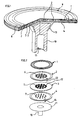
- FIG. 1 clearly shows the schematic structure of a preferred embodiment of the sensor membrane according to the invention.
- the delivery membrane 1 forms the uppermost layer of the sensor membrane. It consists in the embodiment shown of PTFE.
- two sealing beads 8 can be seen, which protrude from the conveying membrane 1.
- the two sealing beads 8 are located in the so-called clamping region 9 of the membrane. This area is clamped under pressure in the clamping bracket of the diaphragm pump provided for this purpose.
- the sealing beads 8 seal the membrane against its holder, so that no liquid can escape from the working space.
- Below the conveying membrane 1, the first conductive membrane layer 2 is arranged below the conveying membrane 1.
- the first conductive membrane layer 2 forms a continuous body, which is manufactured as a part. This can be seen particularly clearly in the exploded view in FIG. Herein, the individual layers of the sensor membrane according to the invention are shown prior to assembly.
- the first conductive membrane layer 2 has openings 6. Below the first conductive membrane layer 2, the insulating membrane layer 3, also made of rubber with plastic fibers, arranged. This has areas 12 which extend beyond the plane formed by the membrane layer 3 upwards and reach through the openings 6 of the first conductive membrane layer 2.
- the second electrically conductive membrane layer 4 is arranged below the insulating membrane layer 3. This has areas 7, which protrude from the plane formed by the membrane layer 4 and through the openings 5 in the insulating membrane layer 3 in the openings 6 of the first conductive Engage membrane layer 2. They are surrounded by the likewise engaging in the openings 6 of the first conductive membrane layer 2 areas 12 of the insulating membrane layer 3 and thus electrically isolated from the first conductive membrane layer 2.
- Figure 3 shows an alternative embodiment to the membrane of Figures 1 and 2 with a slightly different number and arrangement of the through openings. Otherwise, the structure is the same, which is why the same parts are designated by the same reference numerals.
- the individual layers of the membrane are joined together by vulcanization or gluing, so that they form a unit mechanically.
- a membrane core 10 is arranged made of metal or plastic. This consists essentially of a cylindrical rod having a receptacle 15 at the lower end, in which engages the connecting rod of the drive unit.
- the membrane core 10 transmits the translational movement of the drive unit to the layers of the sensor membrane located above the membrane core 10.
- the lowermost insulating membrane layer 11 is designed so that it engages positively in the head 16 of the membrane core 10.
- the translational movement of the membrane core 10 in both the lifting and in the suction direction is transferred to the membrane layers (1, 2, 3, 4, 11) arranged above the core 10. This can also be seen particularly clearly in FIG.
- the electrical contacting of the electrically conductive membrane layers 2, 4 takes place with the aid of metal pins 13 and 14, which pass through the lowermost insulating membrane layer 11 into the corresponding electrically conductive membrane layers. It is important to ensure that the pin 13, which contacts the first electrically conductive membrane layer 2 by means of the material of the insulating membrane layer 3 or with another material with respect to the second electrically conductive membrane layer 4 is isolated.
- the pins 13 and 14 are connected to the two terminals of a resistance measuring device.
- the electrical resistance between the two electrically conductive membranes 2, 4 is measured. If the delivery membrane 1 is intact, i. if it has no continuous cracks or breaks, the surface of the membrane layers located below the delivery membrane 1 will not be wetted by the liquid and the resistance between the first and second electrically conductive layers (2, 4) is extremely large. In case of damage, i.
- the liquid to be conveyed passes through the conveying membrane 1 and wets the surface of the membrane layers underlying the conveying membrane 1, so that the electrical resistance between the first 2 and second 2 electrically conductive membrane layer becomes smaller , eg in the range of 50 M ⁇ and less.
- Such a decrease in the electrical resistance can be detected by the resistance measuring device and triggers when falling below a previously set threshold, an alarm.
- the sensor membrane can be replaced immediately after the occurrence of the leak alarm or after a predetermined time interval.
- the replacement of the membrane is due to the design of their mechanical and electrical connections conceivable simple and executable semi-skilled workers.
- the edge regions of the membrane are clamped in a holder provided for this purpose and are automatically sealed due to the provided sealing beads 8 after clamping.
- the electrical connection to the pins 13 and 14 by means of a standardized connector element.
Landscapes
- Engineering & Computer Science (AREA)
- Mechanical Engineering (AREA)
- General Engineering & Computer Science (AREA)
- Reciprocating Pumps (AREA)
- Investigating Or Analyzing Materials By The Use Of Electric Means (AREA)
- Measuring Fluid Pressure (AREA)
- Investigating Or Analyzing Materials By The Use Of Fluid Adsorption Or Reactions (AREA)
- Diaphragms And Bellows (AREA)
- Laminated Bodies (AREA)
- Separation Using Semi-Permeable Membranes (AREA)
Priority Applications (2)
| Application Number | Priority Date | Filing Date | Title |
|---|---|---|---|
| SI200430443T SI1479910T1 (sl) | 2003-05-20 | 2004-04-22 | Senzorska membrana |
| PL04101686T PL1479910T3 (pl) | 2003-05-20 | 2004-04-22 | Membrana czujnikowa |
Applications Claiming Priority (2)
| Application Number | Priority Date | Filing Date | Title |
|---|---|---|---|
| DE10323059A DE10323059A1 (de) | 2003-05-20 | 2003-05-20 | Sensormembran |
| DE10323059 | 2003-05-20 |
Publications (3)
| Publication Number | Publication Date |
|---|---|
| EP1479910A2 EP1479910A2 (de) | 2004-11-24 |
| EP1479910A3 EP1479910A3 (de) | 2005-09-21 |
| EP1479910B1 true EP1479910B1 (de) | 2007-09-05 |
Family
ID=33039255
Family Applications (1)
| Application Number | Title | Priority Date | Filing Date |
|---|---|---|---|
| EP04101686A Expired - Lifetime EP1479910B1 (de) | 2003-05-20 | 2004-04-22 | Sensormembran |
Country Status (9)
| Country | Link |
|---|---|
| US (1) | US6935180B2 (pl) |
| EP (1) | EP1479910B1 (pl) |
| JP (1) | JP4666340B2 (pl) |
| AT (1) | ATE372461T1 (pl) |
| DE (2) | DE10323059A1 (pl) |
| DK (1) | DK1479910T3 (pl) |
| ES (1) | ES2290626T3 (pl) |
| PL (1) | PL1479910T3 (pl) |
| SI (1) | SI1479910T1 (pl) |
Cited By (2)
| Publication number | Priority date | Publication date | Assignee | Title |
|---|---|---|---|---|
| EP3025077B1 (de) | 2013-07-22 | 2017-09-06 | GEMÜ Gebr. Müller Apparatebau GmbH & Co. Kommanditgesellschaft | Membran und verfahren zu deren herstellung |
| EP3604876B1 (de) | 2018-08-03 | 2021-03-10 | SISTO Armaturen S.A. | Membrandiagnose über luftschnittstelle |
Families Citing this family (16)
| Publication number | Priority date | Publication date | Assignee | Title |
|---|---|---|---|---|
| US6941853B2 (en) * | 2003-12-02 | 2005-09-13 | Wanner Engineering, Inc. | Pump diaphragm rupture detection |
| GB2433298A (en) * | 2005-12-13 | 2007-06-20 | Joseph Anthony Griffiths | Diaphragm with rupture detection |
| US20080003120A1 (en) * | 2006-06-30 | 2008-01-03 | Meza Humberto V | Pump apparatus and method |
| DE102009023012A1 (de) * | 2009-05-28 | 2010-12-16 | G.S. Anderson Gmbh | Membranventil-Membran |
| GB201015586D0 (en) | 2010-09-17 | 2010-10-27 | Qinetiq Ltd | Leakage censor |
| JP6271871B2 (ja) * | 2013-06-04 | 2018-01-31 | 株式会社フジキン | ダイヤフラム弁 |
| US10330094B2 (en) | 2013-08-26 | 2019-06-25 | Blue-White Industries, Ltd. | Sealing diaphragm and methods of manufacturing said diaphragm |
| WO2017125349A1 (en) * | 2016-01-21 | 2017-07-27 | Tetra Laval Holdings & Finance S.A. | Membrane pump with leakage detection |
| DE102016001806B4 (de) * | 2016-02-17 | 2022-10-13 | Timmer Gmbh | Membranpumpe, Membran für eine Membranpumpe und Verfahren zum Nachweis einer defekten Membran einer Membranpumpe |
| CH712963A1 (de) * | 2016-09-29 | 2018-03-29 | Daetwyler Schweiz Ag | Pumpenmembran für eine Membranpumpe zur Förderung eines Fluides. |
| CN106841327A (zh) * | 2017-04-06 | 2017-06-13 | 重庆华伟沃电科技有限公司 | 一种带破损检测传感器的窨井盖 |
| EP3415759B1 (de) | 2017-06-13 | 2020-12-02 | SISTO Armaturen S.A. | Membran mit leitfähigen strukturen |
| DE102019109283A1 (de) * | 2019-04-09 | 2020-10-15 | Prominent Gmbh | Membranbruchüberwachung |
| TWI864482B (zh) * | 2022-11-10 | 2024-12-01 | 茂特隆股份有限公司 | 壓力感測膜片 |
| DE102023132946A1 (de) * | 2023-11-27 | 2025-05-28 | Prominent Gmbh | Membranbruchmeldeeinrichtung |
| DE102024210443A1 (de) * | 2024-10-30 | 2026-04-30 | Robert Bosch Gesellschaft mit beschränkter Haftung | Membran für Membranpumpe |
Family Cites Families (17)
| Publication number | Priority date | Publication date | Assignee | Title |
|---|---|---|---|---|
| JPS5153402Y2 (pl) * | 1971-07-28 | 1976-12-21 | ||
| US4177680A (en) * | 1977-10-14 | 1979-12-11 | Bunker Ramo Corporation | Dual pressure sensor |
| US4569634A (en) * | 1984-09-27 | 1986-02-11 | Mantell Myron E | Failure sensing diaphragm for a diaphragm pump |
| JPS6282286A (ja) * | 1985-10-04 | 1987-04-15 | Nikkiso Co Ltd | ダイアフラムポンプ用ダイアフラム |
| US4781535A (en) * | 1987-11-13 | 1988-11-01 | Pulsafeeder, Inc. | Apparatus and method for sensing diaphragm failures in reciprocating pumps |
| JPH0285193A (ja) * | 1988-09-22 | 1990-03-26 | Mitsubishi Kasei Corp | 非導電性材料ライニング金属製機器 |
| JPH0337503A (ja) * | 1989-07-03 | 1991-02-18 | Kayaba Ind Co Ltd | 歪ゲージ |
| DE4018464A1 (de) * | 1990-06-08 | 1991-12-12 | Ott Kg Lewa | Membran fuer eine hydraulisch angetriebene membranpumpe |
| AU5352594A (en) * | 1993-08-23 | 1995-03-21 | W.L. Gore & Associates, Inc. | Pre-failure warning pump diaphragm |
| IT1273394B (it) | 1994-03-31 | 1997-07-08 | Tetra Brik Res Dev Spa | Dispositivo per la rilevazione di una perdita |
| SE506558C2 (sv) * | 1994-04-14 | 1998-01-12 | Cecap Ab | Givarelement för tryckgivare |
| US5560279A (en) * | 1995-03-16 | 1996-10-01 | W. L. Gore & Associates, Inc. | Pre-failure sensing diaphragm |
| DE19750131C2 (de) * | 1997-11-13 | 2002-06-13 | Infineon Technologies Ag | Mikromechanische Differenzdrucksensorvorrichtung |
| DE19829084B4 (de) * | 1998-06-30 | 2005-01-13 | Prominent Dosiertechnik Gmbh | Membranpumpe |
| DE19925508A1 (de) * | 1999-06-04 | 2000-12-21 | Freudenberg Carl Fa | Einrichtung zur Erkennung von Undichtheiten an Membranen |
| JP2001041838A (ja) * | 1999-08-03 | 2001-02-16 | Yamatake Corp | 圧力センサおよびその製造方法 |
| EP1156214A1 (de) * | 2000-05-18 | 2001-11-21 | Firma Carl Freudenberg | Einrichtung zur Erfassung von Pumpenbetriebsparametern einer Membranfördereinheit |
-
2003
- 2003-05-20 DE DE10323059A patent/DE10323059A1/de not_active Withdrawn
-
2004
- 2004-04-22 PL PL04101686T patent/PL1479910T3/pl unknown
- 2004-04-22 AT AT04101686T patent/ATE372461T1/de active
- 2004-04-22 SI SI200430443T patent/SI1479910T1/sl unknown
- 2004-04-22 DE DE502004004843T patent/DE502004004843D1/de not_active Expired - Lifetime
- 2004-04-22 DK DK04101686T patent/DK1479910T3/da active
- 2004-04-22 EP EP04101686A patent/EP1479910B1/de not_active Expired - Lifetime
- 2004-04-22 ES ES04101686T patent/ES2290626T3/es not_active Expired - Lifetime
- 2004-05-17 JP JP2004146008A patent/JP4666340B2/ja not_active Expired - Fee Related
- 2004-05-19 US US10/848,807 patent/US6935180B2/en not_active Expired - Lifetime
Cited By (4)
| Publication number | Priority date | Publication date | Assignee | Title |
|---|---|---|---|---|
| EP3025077B1 (de) | 2013-07-22 | 2017-09-06 | GEMÜ Gebr. Müller Apparatebau GmbH & Co. Kommanditgesellschaft | Membran und verfahren zu deren herstellung |
| EP3025077B2 (de) † | 2013-07-22 | 2020-09-30 | GEMÜ Gebr. Müller Apparatebau GmbH & Co. Kommanditgesellschaft | Membran und verfahren zu deren herstellung |
| EP3604876B1 (de) | 2018-08-03 | 2021-03-10 | SISTO Armaturen S.A. | Membrandiagnose über luftschnittstelle |
| EP3604876B2 (de) † | 2018-08-03 | 2024-04-03 | SISTO Armaturen S.A. | Membrandiagnose über luftschnittstelle |
Also Published As
| Publication number | Publication date |
|---|---|
| EP1479910A2 (de) | 2004-11-24 |
| JP4666340B2 (ja) | 2011-04-06 |
| PL1479910T3 (pl) | 2008-01-31 |
| ATE372461T1 (de) | 2007-09-15 |
| EP1479910A3 (de) | 2005-09-21 |
| JP2004347115A (ja) | 2004-12-09 |
| US20040261536A1 (en) | 2004-12-30 |
| DK1479910T3 (da) | 2008-04-21 |
| DE10323059A1 (de) | 2004-12-09 |
| DE502004004843D1 (de) | 2007-10-18 |
| US6935180B2 (en) | 2005-08-30 |
| ES2290626T3 (es) | 2008-02-16 |
| SI1479910T1 (sl) | 2007-12-31 |
Similar Documents
| Publication | Publication Date | Title |
|---|---|---|
| EP1479910B1 (de) | Sensormembran | |
| DE69313670T2 (de) | Störungsvoraussage bei einem pumpmembran | |
| DE19926372C2 (de) | Einrichtung zur Erkennung von Undichtheiten an Membranen | |
| CH616269A5 (pl) | ||
| WO2014095419A1 (de) | VORRICHTUNG ZUR BESTIMMUNG ODER ÜBERWACHUNG EINER PROZESSGRÖßE EINES MEDIUMS IN EINER ROHRLEITUNG | |
| WO2016016172A1 (de) | Wasserabscheideelement mit wasserdetektionselektroden | |
| DE102016217166B4 (de) | Gassensor | |
| WO2001088375A1 (de) | Einrichtung zur überwachung der unversehrtheit einer membran | |
| EP1164292A1 (de) | Einrichtung zur Erkennung von Undichtheiten an Membranen | |
| EP3299807A1 (de) | Vorrichtung für den nachweis von organischen verbindungen | |
| DE102019109283A1 (de) | Membranbruchüberwachung | |
| DE102010035696A1 (de) | Elektrisch leitende Verbindung und Verbundglasscheibe damit | |
| DE4027027C2 (de) | Verfahren zur Erkennung einer Bruchstelle in einer Membran und Membranfördereinheit | |
| DE19829084B4 (de) | Membranpumpe | |
| DE3150435C2 (pl) | ||
| DE2624129A1 (de) | Membranpumpe | |
| DE69937251T2 (de) | Vorrichtung zur messung eines mediums unter druck | |
| DE102007049526A1 (de) | Vorrichtung zur Bestimmung und/oder Überwachung einer Prozessgröße | |
| EP2546524B1 (de) | Magnetgekoppelte Kreiselpumpe mit Spalttopfüberwachung | |
| WO2001088376A1 (de) | Verfahren und einrichtung zur erfassung von pumpenbetriebsparametern einer membranfördereinheit | |
| DE20206914U1 (de) | Membran für Ventile, Pumpen u.dgl. | |
| DE818060C (de) | Geraet zum Abschalten einer elektrischen stromverbrauchenden Einrichtung in Abhaengigkeit vom Stand des Spiegels einer Fluessigkeit | |
| WO2024023354A1 (de) | Vorrichtung für eine armatur der prozessfluidtechnik | |
| DE19961210A1 (de) | Messfühler zur Lebensmittelkontrolle | |
| AT393903B (de) | Heizblock |
Legal Events
| Date | Code | Title | Description |
|---|---|---|---|
| PUAI | Public reference made under article 153(3) epc to a published international application that has entered the european phase |
Free format text: ORIGINAL CODE: 0009012 |
|
| AK | Designated contracting states |
Kind code of ref document: A2 Designated state(s): AT BE BG CH CY CZ DE DK EE ES FI FR GB GR HU IE IT LI LU MC NL PL PT RO SE SI SK TR |
|
| AX | Request for extension of the european patent |
Extension state: AL HR LT LV MK |
|
| PUAL | Search report despatched |
Free format text: ORIGINAL CODE: 0009013 |
|
| AK | Designated contracting states |
Kind code of ref document: A3 Designated state(s): AT BE BG CH CY CZ DE DK EE ES FI FR GB GR HU IE IT LI LU MC NL PL PT RO SE SI SK TR |
|
| AX | Request for extension of the european patent |
Extension state: AL HR LT LV MK |
|
| 17P | Request for examination filed |
Effective date: 20060301 |
|
| AKX | Designation fees paid |
Designated state(s): AT BE BG CH CY CZ DE DK EE ES FI FR GB GR HU IE IT LI LU MC NL PL PT RO SE SI SK TR |
|
| GRAP | Despatch of communication of intention to grant a patent |
Free format text: ORIGINAL CODE: EPIDOSNIGR1 |
|
| GRAS | Grant fee paid |
Free format text: ORIGINAL CODE: EPIDOSNIGR3 |
|
| GRAA | (expected) grant |
Free format text: ORIGINAL CODE: 0009210 |
|
| AK | Designated contracting states |
Kind code of ref document: B1 Designated state(s): AT BE BG CH CY CZ DE DK EE ES FI FR GB GR HU IE IT LI LU MC NL PL PT RO SE SI SK TR |
|
| REG | Reference to a national code |
Ref country code: GB Ref legal event code: FG4D Free format text: NOT ENGLISH |
|
| REG | Reference to a national code |
Ref country code: CH Ref legal event code: EP |
|
| REF | Corresponds to: |
Ref document number: 502004004843 Country of ref document: DE Date of ref document: 20071018 Kind code of ref document: P |
|
| REG | Reference to a national code |
Ref country code: CH Ref legal event code: NV Representative=s name: ISLER & PEDRAZZINI AG |
|
| REG | Reference to a national code |
Ref country code: IE Ref legal event code: FG4D Free format text: LANGUAGE OF EP DOCUMENT: GERMAN |
|
| GBT | Gb: translation of ep patent filed (gb section 77(6)(a)/1977) |
Effective date: 20071012 |
|
| REG | Reference to a national code |
Ref country code: SE Ref legal event code: TRGR |
|
| REG | Reference to a national code |
Ref country code: RO Ref legal event code: EPE |
|
| ET | Fr: translation filed | ||
| PG25 | Lapsed in a contracting state [announced via postgrant information from national office to epo] |
Ref country code: FI Free format text: LAPSE BECAUSE OF FAILURE TO SUBMIT A TRANSLATION OF THE DESCRIPTION OR TO PAY THE FEE WITHIN THE PRESCRIBED TIME-LIMIT Effective date: 20070905 |
|
| REG | Reference to a national code |
Ref country code: PL Ref legal event code: T3 |
|
| REG | Reference to a national code |
Ref country code: ES Ref legal event code: FG2A Ref document number: 2290626 Country of ref document: ES Kind code of ref document: T3 |
|
| REG | Reference to a national code |
Ref country code: IE Ref legal event code: FD4D |
|
| REG | Reference to a national code |
Ref country code: DK Ref legal event code: T3 |
|
| PG25 | Lapsed in a contracting state [announced via postgrant information from national office to epo] |
Ref country code: GR Free format text: LAPSE BECAUSE OF FAILURE TO SUBMIT A TRANSLATION OF THE DESCRIPTION OR TO PAY THE FEE WITHIN THE PRESCRIBED TIME-LIMIT Effective date: 20071206 |
|
| PG25 | Lapsed in a contracting state [announced via postgrant information from national office to epo] |
Ref country code: IE Free format text: LAPSE BECAUSE OF FAILURE TO SUBMIT A TRANSLATION OF THE DESCRIPTION OR TO PAY THE FEE WITHIN THE PRESCRIBED TIME-LIMIT Effective date: 20070905 Ref country code: PT Free format text: LAPSE BECAUSE OF FAILURE TO SUBMIT A TRANSLATION OF THE DESCRIPTION OR TO PAY THE FEE WITHIN THE PRESCRIBED TIME-LIMIT Effective date: 20080206 |
|
| REG | Reference to a national code |
Ref country code: HU Ref legal event code: AG4A Ref document number: E002822 Country of ref document: HU |
|
| PLBE | No opposition filed within time limit |
Free format text: ORIGINAL CODE: 0009261 |
|
| STAA | Information on the status of an ep patent application or granted ep patent |
Free format text: STATUS: NO OPPOSITION FILED WITHIN TIME LIMIT |
|
| 26N | No opposition filed |
Effective date: 20080606 |
|
| PG25 | Lapsed in a contracting state [announced via postgrant information from national office to epo] |
Ref country code: MC Free format text: LAPSE BECAUSE OF NON-PAYMENT OF DUE FEES Effective date: 20080430 |
|
| PG25 | Lapsed in a contracting state [announced via postgrant information from national office to epo] |
Ref country code: EE Free format text: LAPSE BECAUSE OF FAILURE TO SUBMIT A TRANSLATION OF THE DESCRIPTION OR TO PAY THE FEE WITHIN THE PRESCRIBED TIME-LIMIT Effective date: 20070905 |
|
| PG25 | Lapsed in a contracting state [announced via postgrant information from national office to epo] |
Ref country code: CY Free format text: LAPSE BECAUSE OF FAILURE TO SUBMIT A TRANSLATION OF THE DESCRIPTION OR TO PAY THE FEE WITHIN THE PRESCRIBED TIME-LIMIT Effective date: 20070905 |
|
| PG25 | Lapsed in a contracting state [announced via postgrant information from national office to epo] |
Ref country code: BG Free format text: LAPSE BECAUSE OF FAILURE TO SUBMIT A TRANSLATION OF THE DESCRIPTION OR TO PAY THE FEE WITHIN THE PRESCRIBED TIME-LIMIT Effective date: 20071205 |
|
| PG25 | Lapsed in a contracting state [announced via postgrant information from national office to epo] |
Ref country code: LU Free format text: LAPSE BECAUSE OF NON-PAYMENT OF DUE FEES Effective date: 20080422 |
|
| PG25 | Lapsed in a contracting state [announced via postgrant information from national office to epo] |
Ref country code: TR Free format text: LAPSE BECAUSE OF FAILURE TO SUBMIT A TRANSLATION OF THE DESCRIPTION OR TO PAY THE FEE WITHIN THE PRESCRIBED TIME-LIMIT Effective date: 20070905 |
|
| PGFP | Annual fee paid to national office [announced via postgrant information from national office to epo] |
Ref country code: RO Payment date: 20140324 Year of fee payment: 11 |
|
| PGFP | Annual fee paid to national office [announced via postgrant information from national office to epo] |
Ref country code: PL Payment date: 20140326 Year of fee payment: 11 |
|
| REG | Reference to a national code |
Ref country code: DE Ref legal event code: R082 Ref document number: 502004004843 Country of ref document: DE Representative=s name: WSL PATENTANWAELTE PARTNERSCHAFT MBB, DE |
|
| REG | Reference to a national code |
Ref country code: DE Ref legal event code: R082 Ref document number: 502004004843 Country of ref document: DE Representative=s name: WSL PATENTANWAELTE PARTNERSCHAFT MBB, DE Effective date: 20140613 Ref country code: DE Ref legal event code: R081 Ref document number: 502004004843 Country of ref document: DE Owner name: PROMINENT GMBH, DE Free format text: FORMER OWNER: PROMINENT DOSIERTECHNIK GMBH, 69123 HEIDELBERG, DE Effective date: 20140613 |
|
| PGFP | Annual fee paid to national office [announced via postgrant information from national office to epo] |
Ref country code: GB Payment date: 20140422 Year of fee payment: 11 |
|
| PGFP | Annual fee paid to national office [announced via postgrant information from national office to epo] |
Ref country code: SE Payment date: 20140418 Year of fee payment: 11 Ref country code: CZ Payment date: 20140416 Year of fee payment: 11 Ref country code: SI Payment date: 20140328 Year of fee payment: 11 Ref country code: NL Payment date: 20140418 Year of fee payment: 11 Ref country code: AT Payment date: 20140411 Year of fee payment: 11 Ref country code: SK Payment date: 20140417 Year of fee payment: 11 Ref country code: IT Payment date: 20140422 Year of fee payment: 11 Ref country code: ES Payment date: 20140428 Year of fee payment: 11 Ref country code: CH Payment date: 20140418 Year of fee payment: 11 Ref country code: FR Payment date: 20140422 Year of fee payment: 11 |
|
| PGFP | Annual fee paid to national office [announced via postgrant information from national office to epo] |
Ref country code: HU Payment date: 20140422 Year of fee payment: 11 Ref country code: BE Payment date: 20140418 Year of fee payment: 11 Ref country code: DK Payment date: 20140422 Year of fee payment: 11 |
|
| REG | Reference to a national code |
Ref country code: DK Ref legal event code: EBP Effective date: 20150430 |
|
| REG | Reference to a national code |
Ref country code: CH Ref legal event code: PL |
|
| REG | Reference to a national code |
Ref country code: SE Ref legal event code: EUG Ref country code: AT Ref legal event code: MM01 Ref document number: 372461 Country of ref document: AT Kind code of ref document: T Effective date: 20150422 |
|
| GBPC | Gb: european patent ceased through non-payment of renewal fee |
Effective date: 20150422 |
|
| REG | Reference to a national code |
Ref country code: NL Ref legal event code: MM Effective date: 20150501 |
|
| REG | Reference to a national code |
Ref country code: SK Ref legal event code: MM4A Ref document number: E 2990 Country of ref document: SK Effective date: 20150422 |
|
| PG25 | Lapsed in a contracting state [announced via postgrant information from national office to epo] |
Ref country code: CH Free format text: LAPSE BECAUSE OF NON-PAYMENT OF DUE FEES Effective date: 20150430 Ref country code: LI Free format text: LAPSE BECAUSE OF NON-PAYMENT OF DUE FEES Effective date: 20150430 Ref country code: GB Free format text: LAPSE BECAUSE OF NON-PAYMENT OF DUE FEES Effective date: 20150422 Ref country code: IT Free format text: LAPSE BECAUSE OF NON-PAYMENT OF DUE FEES Effective date: 20150422 |
|
| REG | Reference to a national code |
Ref country code: FR Ref legal event code: ST Effective date: 20151231 Ref country code: SI Ref legal event code: KO00 Effective date: 20151216 |
|
| PG25 | Lapsed in a contracting state [announced via postgrant information from national office to epo] |
Ref country code: SI Free format text: LAPSE BECAUSE OF NON-PAYMENT OF DUE FEES Effective date: 20150423 Ref country code: AT Free format text: LAPSE BECAUSE OF NON-PAYMENT OF DUE FEES Effective date: 20150422 Ref country code: SE Free format text: LAPSE BECAUSE OF NON-PAYMENT OF DUE FEES Effective date: 20150423 Ref country code: CZ Free format text: LAPSE BECAUSE OF NON-PAYMENT OF DUE FEES Effective date: 20150422 Ref country code: HU Free format text: LAPSE BECAUSE OF NON-PAYMENT OF DUE FEES Effective date: 20150423 Ref country code: SK Free format text: LAPSE BECAUSE OF NON-PAYMENT OF DUE FEES Effective date: 20150422 Ref country code: RO Free format text: LAPSE BECAUSE OF NON-PAYMENT OF DUE FEES Effective date: 20150422 Ref country code: FR Free format text: LAPSE BECAUSE OF NON-PAYMENT OF DUE FEES Effective date: 20150430 |
|
| PG25 | Lapsed in a contracting state [announced via postgrant information from national office to epo] |
Ref country code: NL Free format text: LAPSE BECAUSE OF NON-PAYMENT OF DUE FEES Effective date: 20150501 |
|
| PG25 | Lapsed in a contracting state [announced via postgrant information from national office to epo] |
Ref country code: DK Free format text: LAPSE BECAUSE OF NON-PAYMENT OF DUE FEES Effective date: 20150430 |
|
| REG | Reference to a national code |
Ref country code: ES Ref legal event code: FD2A Effective date: 20160526 |
|
| PG25 | Lapsed in a contracting state [announced via postgrant information from national office to epo] |
Ref country code: ES Free format text: LAPSE BECAUSE OF NON-PAYMENT OF DUE FEES Effective date: 20150423 |
|
| PG25 | Lapsed in a contracting state [announced via postgrant information from national office to epo] |
Ref country code: PL Free format text: LAPSE BECAUSE OF NON-PAYMENT OF DUE FEES Effective date: 20150422 |
|
| PG25 | Lapsed in a contracting state [announced via postgrant information from national office to epo] |
Ref country code: BE Free format text: LAPSE BECAUSE OF NON-PAYMENT OF DUE FEES Effective date: 20150430 |
|
| PGFP | Annual fee paid to national office [announced via postgrant information from national office to epo] |
Ref country code: DE Payment date: 20200615 Year of fee payment: 17 |
|
| REG | Reference to a national code |
Ref country code: DE Ref legal event code: R119 Ref document number: 502004004843 Country of ref document: DE |
|
| PG25 | Lapsed in a contracting state [announced via postgrant information from national office to epo] |
Ref country code: DE Free format text: LAPSE BECAUSE OF NON-PAYMENT OF DUE FEES Effective date: 20211103 |