EP1479083B1 - Abstandhalter f r ein brennelement eines siedewasserreaktors - Google Patents
Abstandhalter f r ein brennelement eines siedewasserreaktors Download PDFInfo
- Publication number
- EP1479083B1 EP1479083B1 EP03702395A EP03702395A EP1479083B1 EP 1479083 B1 EP1479083 B1 EP 1479083B1 EP 03702395 A EP03702395 A EP 03702395A EP 03702395 A EP03702395 A EP 03702395A EP 1479083 B1 EP1479083 B1 EP 1479083B1
- Authority
- EP
- European Patent Office
- Prior art keywords
- gills
- spacer
- webs
- projection
- fuel
- Prior art date
- Legal status (The legal status is an assumption and is not a legal conclusion. Google has not performed a legal analysis and makes no representation as to the accuracy of the status listed.)
- Expired - Lifetime
Links
- 239000000446 fuel Substances 0.000 title claims description 26
- 125000006850 spacer group Chemical group 0.000 title claims description 14
- XLYOFNOQVPJJNP-UHFFFAOYSA-N water Substances O XLYOFNOQVPJJNP-UHFFFAOYSA-N 0.000 title claims description 5
- 238000009835 boiling Methods 0.000 title claims description 4
- 210000002816 gill Anatomy 0.000 claims description 17
- 230000037431 insertion Effects 0.000 description 4
- 238000003780 insertion Methods 0.000 description 4
- 239000002826 coolant Substances 0.000 description 2
- 230000005855 radiation Effects 0.000 description 2
- 239000006228 supernatant Substances 0.000 description 2
- 229910001111 Fine metal Inorganic materials 0.000 description 1
- 230000000295 complement effect Effects 0.000 description 1
- 230000009977 dual effect Effects 0.000 description 1
- 239000002923 metal particle Substances 0.000 description 1
- 238000007790 scraping Methods 0.000 description 1
Images


Classifications
-
- G—PHYSICS
- G21—NUCLEAR PHYSICS; NUCLEAR ENGINEERING
- G21C—NUCLEAR REACTORS
- G21C3/00—Reactor fuel elements and their assemblies; Selection of substances for use as reactor fuel elements
- G21C3/30—Assemblies of a number of fuel elements in the form of a rigid unit
- G21C3/32—Bundles of parallel pin-, rod-, or tube-shaped fuel elements
- G21C3/34—Spacer grids
- G21C3/352—Spacer grids formed of assembled intersecting strips
-
- Y—GENERAL TAGGING OF NEW TECHNOLOGICAL DEVELOPMENTS; GENERAL TAGGING OF CROSS-SECTIONAL TECHNOLOGIES SPANNING OVER SEVERAL SECTIONS OF THE IPC; TECHNICAL SUBJECTS COVERED BY FORMER USPC CROSS-REFERENCE ART COLLECTIONS [XRACs] AND DIGESTS
- Y02—TECHNOLOGIES OR APPLICATIONS FOR MITIGATION OR ADAPTATION AGAINST CLIMATE CHANGE
- Y02E—REDUCTION OF GREENHOUSE GAS [GHG] EMISSIONS, RELATED TO ENERGY GENERATION, TRANSMISSION OR DISTRIBUTION
- Y02E30/00—Energy generation of nuclear origin
- Y02E30/30—Nuclear fission reactors
Definitions
- the invention relates to a spacer for a fuel assembly of a boiling water reactor.
- a spacer for a fuel assembly of a boiling water reactor is usually composed of crosswise nested inner webs and this comprehensive, formed from outer webs frame together.
- the outer webs there are openings which serve to detach a coolant film flowing along the inner wall of the fuel channel and to guide it inwards so that the coolant comes into contact with the fuel rods.
- the upper edge of the opening and the adjoining wall portion of the outer webs is bulged outward.
- This embodiment is commonly referred to as a gill.
- the object of the invention is therefore to propose a spacer, which provides a remedy.
- This object is achieved according to claim 1, characterized in that on the outer side of the outer webs a plurality of projections formed by Wandausbuchtung are present, the supernatant is greater than the supernatant of the gills. In this way it is effectively prevented that when inserting a fuel bundle in a flow guide box damaged gills or metal particles are planed from the flow guide box.
- the projections are arranged below the gills. In this way, it is prevented that these collide with the upper edge of the fuel rod bundle when it is introduced into the flow guide box, which must be done for reasons of radiation protection under a water cover of several meters.
- the measure aims to provide the projections at its lower edge with a deflector flag angled towards the center of the spacer.
- the deflector vanes impinge on the upper edge of the flow guide box first and cause centering of the fuel bundle and smooth insertion.
- the projections then fulfill a dual function, since they also serve as Einfädel Anlagen.
- the projections are arranged in the region of an inner web, whereby the forces acting on them are forwarded into the inner webs.
- the inner web can be used both to support the projection, as well as the deflector flag integrally formed on it.
- this has a first and second support portion, wherein the first support portion hineinerstreckt into the projection and there cooperates with the inner wall and wherein the second portion has a beveled edge against which the deflector tab abuts.
- the fixation of an inner web in the region of a projection is accomplished in a preferred embodiment in that in the wall of the projection an axially or in the longitudinal direction of the fuel element extending slot is present, which is at least partially penetrated by the first support portion.
- the slot is disposed in an outside recess of the projection.
- a spacer 1 for the fuel element of a boiling water reactor is composed of crosswise interlocked inner webs 2 and a frame comprising outer webs 3 comprising them.
- the inner webs 2 form cells that are interspersed in the assembled state of fuel rods 4.
- On the outside of the outer webs 3 a plurality of gills 5 are arranged. These comprise an opening 6 whose upper edge and the adjoining wall portion 7, bulging outward.
- protrusions 9 formed by wall bulges project from the outer side of the outer webs 3.
- the projection of the projections 9 is greater than the projection of the gills 5, so that in the assembled state, or during the insertion of a fuel assembly in a fuel assembly 8, the distance 10 of the gills 5 to the inside of the fuel box 8 is greater than the distance 11 between the projection 9 and the fuel assembly 8.
- an approximately spatulate and inwardly bent deflector flag 13 is formed.
- a recess 14 is provided, in which a slot 16 extending in the axial direction 15 is arranged.
- an inner web 2 which is assigned to the projection 9 is integrally formed with a first support section 17 protruding beyond its side edge, which extends into the projection 9, wherein the support section 17 has an outline contour corresponding to the inner contour of the projection 9 having.
- a connection tab 21 is formed, which passes through the slot 16.
- the connecting strap 21 is fixed from the outside of the projection 9 with a weld 18 on the outer web 3.
- a second support portion 19 is integrally formed, which has a for oblique position of the deflector lug 13 complementary aligned bevel 20. At this the deflector flag 13 is supported.
Description
- Die Erfindung betrifft einen Abstandhalter für ein Brennelement eines Siedewasserreaktors. Ein solcher z.B. aus der
US 4,999,153 bekannter Abstandhalter setzt sich in der Regel aus kreuzweise ineinandergesteckten Innenstegen und einen diese umfassenden, aus Außenstegen gebildeten Rahmen zusammen. In den Außenstegen sind Öffnungen vorhanden, die dazu dienen, einen an der Innenwandung des Brennelementkastens entlangströmenden Kühlmittelfilm abzulösen und nach innen zu leiten, damit das Kühlmittel mit den Brennstäben in Kontakt kommt. Der obere Rand der Öffnung und der sich daran anschließende Wandbereich der Außenstege ist nach außen vorgewölbt. Diese Ausgestaltung wird üblicherweise als Kieme bezeichnet. - Zur Reparatur eines Brennelements, beispielsweise zum Austausch eines Brennstabes, ist es erforderlich, dass das Brennelementbündel aus dem Strömungsführungskasten herausgenommen und später wieder eingeführt werden muss. Der Überstand der Kiemen ist zwar so bemessen, dass im Einbauzustand zwischen den Kiemen und dem Brennelementkasten ein Spalt vorhanden ist, um etwa strahleninduziertes Breitenwachstum im Falle von Abstandhaltern aus Zirkaloy zu ermöglichen. Dieser Spalt verhindert aber nicht, dass die Kiemen mit der Innenwand des Brennelementkastens in Berührung kommmt. Dabei besteht die Gefahr, dass die vorstehenden Kiemen an der Innenseite des Brennelements entlangschaben und feine Metallspäne abheben oder dass sie selbst beschädigt werden.
- Aufgabe der Erfindung ist es daher, einen Abstandhalter vorzuschlagen, der hier Abhilfe schafft.
- Diese Aufgabe wird gemäß Anspruch 1 dadurch gelöst, dass an der Außenseite der Außenstege mehrere, durch Wandausbuchtung gebildete Vorsprünge vorhanden sind, deren Überstand größer ist, als der Überstand der Kiemen. Auf diese Weise ist wirksam verhindert, dass beim Einführen eines Brennelementbündels in einen Strömungsführungskasten Kiemen beschädigt oder Metallpartikel vom Strömungsführungskasten abgehobelt werden. Die Vorsprünge sind unterhalb der Kiemen angeordnet. Auf diese Weise ist verhindert, dass diese beim Einführen des Brennstabbündels in den Strömungsführungskasten, was ja aus Strahlenschutzgründen unter einer Wasserüberdeckung von mehreren Metern erfolgen muss, mit dessen oberen Rand kollidieren. In die gleiche Richtung zielt die Maßnahme, die Vorsprünge an ihrem unteren Rand mit einer zum Zentrum des Abstandhalters hin abgewinkelten Abweiserfahne zu versehen. Wenn sich das Brennstabbündel beim Einführen in den Strömungsführungskasten verdrillt, treffen zuerst die Abweiserfahnen auf die Oberkante des Strömungsführungskastens auf und bewirken eine Zentrierung des Brennstabbündels und ein reibungsloses Einführen. Die Vorsprünge erfüllen dann eine Doppelfunktion, da diese gleichzeitig als Einfädelhilfe dienen. Vorzugsweise sind die Vorsprünge im Bereich eines Innensteges angeordnet, wodurch die auf sie einwirkenden Kräfte in die Innenstege weitergeleitet werden. Außerdem lässt sich der Innensteg sowohl zur Abstützung des Vorsprungs, als auch der an ihn angeformten Abweiserfahne nutzen. Dazu weist dieser einen ersten und zweiten Stützabschnitt auf, wobei sich der erste Stützabschnitt in den Vorsprung hineinerstreckt und dort mit dessen Innenwandung zusammenwirkt und wobei der zweite Abschnitt eine Schrägkante aufweist, an der die Abweiserfahne anliegt.
- Die Fixierung eines Innenstegs im Bereich eines Vorsprungs wird bei einer bevorzugten Ausgestaltung dadurch bewerkstelligt, dass in der Wand des Vorsprung ein sich axial bzw. in Längsrichtung des Brennelements erstreckender Schlitz vorhanden ist, der vom ersten Stützabschnitt zumindest teilweise durchgriffen ist. Der Schlitz ist in einer außenseitigen Vertiefung des Vorsprungs angeordnet. Dies hat den Vorteil, dass dort eine Schweißnaht zum Verbinden des Innenstegs mit dem Außensteg angebracht werden kann, ohne dass diese die Außenfläche des Vorsprungs überragt.
- Die Erfindung wird nun anhand eines in den beigefügten Zeichnungen dargestellten Ausführungsbeispiels näher erläutert. Es zeigen:
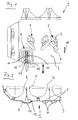
- Fig.1
- den Ausschnitt eines Abstandhalters in Seitenansicht,
- Fig.2
- eine Draufsicht in Richtung des Pfeils II in Fig.1,
- Fig.3
- den teilweise geschnittenen Ausschnitt eines nahe eines Strömungsführungskastens angeordneten Abstandshalters, und
- Fig. 4
- das Detail IV von Fig. 3 in vergrößertem Maßstab.
- Wie den Abbildungen zu entnehmen ist, setzt sich ein Abstandshalter 1 für das Brennelement eines Siedewasserreaktors aus kreuzweise ineinandergesteckten Innenstegen 2 und einem diese umfassenden Rahmen aus Außenstegen 3 zusammen. Die Innenstege 2 bilden Zellen, die im Montagezustand von Brennstäben 4 durchsetzt sind. An der Außenseite der Außenstege 3 sind mehrere Kiemen 5 angeordnet. Diese umfassen eine Öffnung 6 deren oberer Rand und der sich daran und anschließende Wandabschnitt 7, nach außen vorgewölbt sind. Um zu verhindern, dass die Kiemen 5 bzw. der Wandabschnitt 7 beim Einführen eines Brennstabbündels in einen Brennelementkasten 8 mit dessen Innenwand in Berührung kommen, stehen aus der Außenseite der Außenstege 3 durch Wandausbuchtung gebildete Vorsprünge 9 hervor. Der Überstand der Vorsprünge 9 ist dabei größer als der Überstand der Kiemen 5, so dass im Montagezustand, bzw. während des Einführens eines Brennstabbündels in einen Brennelementkasten 8 der Abstand 10 der Kiemen 5 zur Innenseite des Brennelementkastens 8 größer ist, als der Abstand 11 zwischen dem Vorsprung 9 und dem Brennelementkasten 8.
- An der Unterkante 12 des Vorsprungs 9 ist eine etwa spatelförmige und nach innen gebogene Abweiserfahne 13 angeformt. In der Außenseite des Vorsprungs 9 ist eine Vertiefung 14 vorhanden, in der ein sich in Axialrichtung 15 erstreckender Schlitz 16 angeordnet ist. Wie insbesondere Fig.3 und 4 deutlich zu entnehmen ist, ist an dem Vorsprung 9 zugeordneten Innensteg 2 ein über dessen Seitenkante hinausragender erster Stützabschnitt 17 angeformt, der sich in den Vorsprung 9 hineinerstreckt, wobei der Stützabschnitt 17 eine der Innenkontur des Vorsprungs 9 entsprechende Umrissform aufweist. An den ersten Stützabschnitt 17 ist eine Verbindungslasche 21 angeformt, die den Schlitz 16 durchgreift. Die Verbindungslasche 21 ist von der Außenseite des Vorsprungs 9 her mit einer Schweißnaht 18 am Außensteg 3 fixiert. An die Unterkante des Innenstegs 2 ist ein zweiter Stützabschnitt 19 angeformt, der eine zur Schrägstellung der Abweiserfahne 13 komplementär ausgerichtete Schrägkante 20 aufweist. An dieser stützt sich die Abweiserfahne 13 ab.
-
- 1
- Abstandhalter
- 2
- Innensteg
- 3
- Außensteg
- 4
- Brennstab
- 5
- Kieme
- 6
- Öffnung
- 7
- Wandabschnitt
- 8
- Brennelementkasten
- 9
- Vorsprung
- 10
- Abstand
- 11
- Abstand
- 12
- Unterkante
- 13
- Abweiserfahne
- 14
- Vertiefung
- 15
- Axialrichtung
- 16
- Schlitz
- 17
- erster Stützabschnitt
- 18
- Schweißnaht
- 19
- zweiter Stützabschnitt
- 20
- Schrägkante
- 21
- Verbindungslasche
Claims (4)
- Abstandhalter (1) für ein Brennelement eines Siedewasserreaktors, mit einem Rahmen aus Außenstegen (3) und kreuzweise zueinander ausgerichteten Innenstegen (2), wobei an der Außenseite der Außenstege (3) Kiemen (5) angeordnet sind,
dadurch gekennzeichnet,
dass an der Außenseite der Außenstege (3) mehrere durch eine Wandausbuchtung gebildete Vorsprünge (9) vorhanden sind,- deren Überstand größer ist als der Überstand der Kiemen (5),- die unterhalb der Kiemen (5) und im Bereich eines Innensteges (2) angeordnet sind, und an deren Unterkante (12), die weiter aus der Außenseite der Außenstege (3) hervorragt als die Kiemen (5), eine Abweiserfahne (13) angeformt ist. - Abstandhalter nach Anspruch 1,
dadurch gekennzeichnet,
dass an den Innensteg (2) ein über dessen Seitenkante seitlich überstehender erster Stützabschnitt (17) angeformt ist, der sich in den Vorsprung (9) hineinerstreckt und mit diesem verbunden ist. - Abstandhalter nach Anspruch 2,
dadurch gekennzeichnet,
dass an die Unterkante des Innenstegs (2) ein zweiter, eine Schrägkante (20) aufweisender Stützabschnitt (19) angeformt ist, wobei sich die Abweiserfahne (13) an der Schrägkante (20) abstützt. - Abstandhalter nach Anspruch 2 oder 3,
dadurch gekennzeichnet,
dass in der Außenseite des Vorsprungs (9) eine sich in Axialrichtung (15) erstreckende Vertiefung (14) vorhanden ist, in der ein vom ersten Stützabschnitt (17) zumindest teilweise durchgriffener Schlitz (16) angeordnet ist.
Applications Claiming Priority (3)
| Application Number | Priority Date | Filing Date | Title |
|---|---|---|---|
| DE10208502A DE10208502C1 (de) | 2002-02-27 | 2002-02-27 | Abstandhalter für ein Brennelement eines Siedewasserreaktors |
| DE10208502 | 2002-02-27 | ||
| PCT/EP2003/000081 WO2003073435A2 (de) | 2002-02-27 | 2003-01-08 | Abstandhalter für ein brennelement eines siedewasserreaktors |
Publications (2)
| Publication Number | Publication Date |
|---|---|
| EP1479083A2 EP1479083A2 (de) | 2004-11-24 |
| EP1479083B1 true EP1479083B1 (de) | 2007-11-21 |
Family
ID=27762474
Family Applications (1)
| Application Number | Title | Priority Date | Filing Date |
|---|---|---|---|
| EP03702395A Expired - Lifetime EP1479083B1 (de) | 2002-02-27 | 2003-01-08 | Abstandhalter f r ein brennelement eines siedewasserreaktors |
Country Status (7)
| Country | Link |
|---|---|
| US (1) | US7555093B1 (de) |
| EP (1) | EP1479083B1 (de) |
| JP (1) | JP3935882B2 (de) |
| DE (2) | DE10208502C1 (de) |
| ES (1) | ES2295548T3 (de) |
| TW (1) | TW574712B (de) |
| WO (1) | WO2003073435A2 (de) |
Families Citing this family (2)
| Publication number | Priority date | Publication date | Assignee | Title |
|---|---|---|---|---|
| US8369475B2 (en) * | 2009-07-01 | 2013-02-05 | Westinghouse Electric Company Llc | Nuclear fuel assembly support grid |
| EP2525367A1 (de) * | 2011-05-20 | 2012-11-21 | Areva NP | Abstandsgitter für Kernbrennstoffbündel und zugehöriges Kernbrennstoffbündel |
Family Cites Families (22)
| Publication number | Priority date | Publication date | Assignee | Title |
|---|---|---|---|---|
| GB1116811A (en) * | 1964-10-30 | 1968-06-12 | Atomic Energy Authority Uk | Improvements in or relating to nuclear reactor fuel assemblies |
| JPS6066188A (ja) | 1983-09-21 | 1985-04-16 | 株式会社日立製作所 | 燃料スペ−サ |
| US4692302A (en) * | 1983-12-30 | 1987-09-08 | Westinghouse Electric Corp. | Coolant flow mixer grid for a nuclear reactor fuel assembly |
| US4728490A (en) * | 1986-09-17 | 1988-03-01 | Westinghouse Electric Corp. | Fuel rod spacer with perimeter scoops for diverting liquid coolant flow |
| JPH067185B2 (ja) * | 1988-06-17 | 1994-01-26 | 三菱原子燃料株式会社 | 支持格子 |
| JPH0293398A (ja) * | 1988-09-29 | 1990-04-04 | Nuclear Fuel Ind Ltd | 燃料集合体用スペーサ |
| JPH02147889A (ja) * | 1988-11-29 | 1990-06-06 | Nippon Atom Ind Group Co Ltd | 沸騰水型原子炉用燃料集合体 |
| SE464995B (sv) * | 1989-11-14 | 1991-07-08 | Asea Atom Ab | Braenslepatron foer en kokarreaktor |
| JP2751078B2 (ja) * | 1989-12-12 | 1998-05-18 | 原子燃料工業株式会社 | 原子炉燃料集合体用スペーサー及び燃料集合体 |
| US4999153A (en) * | 1990-03-21 | 1991-03-12 | General Electric Company | Flow tripper in combination with spacer deflector |
| ES2078398T3 (es) * | 1991-08-05 | 1995-12-16 | Siemens Ag | Distanciador para elementos combustibles con resortes sobrepuestos, curvados. |
| JP3038266B2 (ja) * | 1991-12-09 | 2000-05-08 | 株式会社東芝 | 燃料スペーサ |
| US5267291A (en) * | 1992-02-21 | 1993-11-30 | General Electric Company | Spacer band with optimized fuel bundle to channel clearance in a boiling water reactor |
| SE470032B (sv) * | 1992-03-17 | 1993-10-25 | Asea Atom Ab | Spridare för sammanhållning av ett antal långsträckta bränslestavar till ett knippe för placering i en kärnreaktor av BWR- eller PWP-typ. |
| JPH05323073A (ja) | 1992-05-18 | 1993-12-07 | Nuclear Fuel Ind Ltd | 燃料集合体及び燃料集合体用スペーサ |
| US5307392A (en) * | 1992-06-29 | 1994-04-26 | Combustion Engineering, Inc. | Energy dissipating outer strip for grid |
| JPH0743486A (ja) | 1993-07-30 | 1995-02-14 | Toshiba Corp | 燃料スペーサ |
| SE509202C2 (sv) * | 1993-09-20 | 1998-12-14 | Asea Atom Ab | Spridare och bränslepatron för en kokarreaktor |
| JPH08297183A (ja) * | 1995-04-27 | 1996-11-12 | Hitachi Ltd | 燃料スペーサ |
| JPH08304574A (ja) * | 1995-05-15 | 1996-11-22 | Nuclear Fuel Ind Ltd | 原子炉燃料集合体用チャンネルボックス及び燃料集合体 |
| JP2001194479A (ja) * | 2000-01-14 | 2001-07-19 | Nuclear Fuel Ind Ltd | 沸騰水型原子炉用燃料集合体のスペーサと、これを用いた沸騰水型原子炉用燃料集合体 |
| KR100475633B1 (ko) * | 2002-10-30 | 2005-03-11 | 한국수력원자력 주식회사 | 핵연료 집합체용 측면 절개형 이중판 노즐형 냉각재 혼합지지격자체 |
-
2002
- 2002-02-27 DE DE10208502A patent/DE10208502C1/de not_active Expired - Fee Related
-
2003
- 2003-01-08 JP JP2003572042A patent/JP3935882B2/ja not_active Expired - Fee Related
- 2003-01-08 ES ES03702395T patent/ES2295548T3/es not_active Expired - Lifetime
- 2003-01-08 EP EP03702395A patent/EP1479083B1/de not_active Expired - Lifetime
- 2003-01-08 WO PCT/EP2003/000081 patent/WO2003073435A2/de active IP Right Grant
- 2003-01-08 DE DE50308644T patent/DE50308644D1/de not_active Expired - Lifetime
- 2003-02-24 TW TW92103783A patent/TW574712B/zh not_active IP Right Cessation
- 2003-10-24 US US10/692,637 patent/US7555093B1/en not_active Expired - Fee Related
Also Published As
| Publication number | Publication date |
|---|---|
| WO2003073435A3 (de) | 2004-01-15 |
| TW574712B (en) | 2004-02-01 |
| EP1479083A2 (de) | 2004-11-24 |
| US7555093B1 (en) | 2009-06-30 |
| TW200307298A (en) | 2003-12-01 |
| WO2003073435A2 (de) | 2003-09-04 |
| US20090180582A1 (en) | 2009-07-16 |
| DE10208502C1 (de) | 2003-09-25 |
| DE50308644D1 (de) | 2008-01-03 |
| JP2005518551A (ja) | 2005-06-23 |
| ES2295548T3 (es) | 2008-04-16 |
| JP3935882B2 (ja) | 2007-06-27 |
Similar Documents
| Publication | Publication Date | Title |
|---|---|---|
| EP0370427B1 (de) | Kerneinbauten eines wassergekühlten Kernreaktors | |
| DE4020592C2 (de) | Wärmetauscher des Gleichstrom-Typs für Fahrzeuge | |
| DE60219596T2 (de) | Filter zum Abtrennen von Partikeln aus Kühlwasser in einer Nuklearanlage | |
| DE2428980A1 (de) | Brennelementbuendel fuer kernreaktoren | |
| AT1085U1 (de) | Spinndüse | |
| EP0523313A1 (de) | Siebelement | |
| DE3327422A1 (de) | Sieb, insbesondere fuer die sortierung von auf der grundlage von altpapier hergestellten fasersuspensionen | |
| DE2102952C3 (de) | Abstandhalteranordnung zur Halterung von Brennstoffelementen in einem Kernreaktor | |
| EP0141208B1 (de) | Kernreaktorbrennelement | |
| EP1820196B1 (de) | Brennelement für einen siedewasserreaktor | |
| DE10259706B4 (de) | Untere Ankerplatte einer Kernbrennstoffkassette und Verfahren zu deren Zusammenbau | |
| EP0141085A1 (de) | Kernreaktorbrennelement | |
| EP0184064B2 (de) | Kernreaktorbrennelement | |
| EP1479083B1 (de) | Abstandhalter f r ein brennelement eines siedewasserreaktors | |
| EP0529128B1 (de) | Kernreaktorbrennelement mit Blattfedern | |
| DE102006053801B4 (de) | Lötdüse zum Wellenlöten von Leiterplatten | |
| DE4307786A1 (de) | Abstandshalter für Kernreaktor-Brennelement | |
| DE10016560A1 (de) | Rotor für eine Papierstoffaufbereitungsmaschine sowie Verschleißschutzelement für einen derartigen Rotor | |
| DE69701337T3 (de) | Führungsrohr für Kernbrennstabbündel | |
| DE3002679A1 (de) | Farbkathodenstrahlroehre | |
| EP1550137B1 (de) | Brennelement eines siedewasserreaktors | |
| DE2829108A1 (de) | Kurvengaengiger plattenbandfoerderer | |
| EP1360696B1 (de) | Brennelement | |
| DE4224727A1 (de) | Siebkorb | |
| EP0932162B1 (de) | Abstandhalter für ein Brennelement eines Kernkraftwerkes |
Legal Events
| Date | Code | Title | Description |
|---|---|---|---|
| PUAI | Public reference made under article 153(3) epc to a published international application that has entered the european phase |
Free format text: ORIGINAL CODE: 0009012 |
|
| 17P | Request for examination filed |
Effective date: 20031020 |
|
| AK | Designated contracting states |
Kind code of ref document: A2 Designated state(s): AT BE BG CH CY CZ DE DK EE ES FI FR GB GR HU IE IT LI LU MC NL PT SE SI SK TR |
|
| RAP1 | Party data changed (applicant data changed or rights of an application transferred) |
Owner name: AREVA NP GMBH |
|
| 17Q | First examination report despatched |
Effective date: 20060901 |
|
| GRAP | Despatch of communication of intention to grant a patent |
Free format text: ORIGINAL CODE: EPIDOSNIGR1 |
|
| GRAS | Grant fee paid |
Free format text: ORIGINAL CODE: EPIDOSNIGR3 |
|
| GRAA | (expected) grant |
Free format text: ORIGINAL CODE: 0009210 |
|
| AK | Designated contracting states |
Kind code of ref document: B1 Designated state(s): CH DE ES FI LI SE |
|
| REG | Reference to a national code |
Ref country code: CH Ref legal event code: EP |
|
| RAP2 | Party data changed (patent owner data changed or rights of a patent transferred) |
Owner name: AREVA NP GMBH |
|
| REF | Corresponds to: |
Ref document number: 50308644 Country of ref document: DE Date of ref document: 20080103 Kind code of ref document: P |
|
| REG | Reference to a national code |
Ref country code: CH Ref legal event code: NV Representative=s name: E. BLUM & CO. AG PATENT- UND MARKENANWAELTE VSP |
|
| REG | Reference to a national code |
Ref country code: SE Ref legal event code: TRGR |
|
| REG | Reference to a national code |
Ref country code: ES Ref legal event code: FG2A Ref document number: 2295548 Country of ref document: ES Kind code of ref document: T3 |
|
| PLBE | No opposition filed within time limit |
Free format text: ORIGINAL CODE: 0009261 |
|
| STAA | Information on the status of an ep patent application or granted ep patent |
Free format text: STATUS: NO OPPOSITION FILED WITHIN TIME LIMIT |
|
| 26N | No opposition filed |
Effective date: 20080822 |
|
| REG | Reference to a national code |
Ref country code: DE Ref legal event code: R082 Ref document number: 50308644 Country of ref document: DE Representative=s name: MOERTEL, ALFRED, DIPL.-PHYS. DR.RER.NAT., DE |
|
| REG | Reference to a national code |
Ref country code: DE Ref legal event code: R082 Ref document number: 50308644 Country of ref document: DE Representative=s name: MOERTEL, ALFRED, DIPL.-PHYS. DR.RER.NAT., DE Effective date: 20131112 Ref country code: DE Ref legal event code: R081 Ref document number: 50308644 Country of ref document: DE Owner name: AREVA GMBH, DE Free format text: FORMER OWNER: AREVA NP GMBH, 91052 ERLANGEN, DE Effective date: 20131112 Ref country code: DE Ref legal event code: R082 Ref document number: 50308644 Country of ref document: DE Representative=s name: MEISSNER BOLTE & PARTNER GBR, DE Effective date: 20131112 Ref country code: DE Ref legal event code: R082 Ref document number: 50308644 Country of ref document: DE Representative=s name: MEISSNER BOLTE PATENTANWAELTE RECHTSANWAELTE P, DE Effective date: 20131112 |
|
| REG | Reference to a national code |
Ref country code: DE Ref legal event code: R082 Ref document number: 50308644 Country of ref document: DE Representative=s name: MEISSNER BOLTE & PARTNER GBR, DE Ref country code: DE Ref legal event code: R082 Ref document number: 50308644 Country of ref document: DE Representative=s name: MEISSNER BOLTE PATENTANWAELTE RECHTSANWAELTE P, DE |
|
| REG | Reference to a national code |
Ref country code: DE Ref legal event code: R082 Ref document number: 50308644 Country of ref document: DE Representative=s name: MEISSNER BOLTE PATENTANWAELTE RECHTSANWAELTE P, DE |
|
| REG | Reference to a national code |
Ref country code: DE Ref legal event code: R082 Ref document number: 50308644 Country of ref document: DE Representative=s name: MEISSNER BOLTE PATENTANWAELTE RECHTSANWAELTE P, DE Ref country code: DE Ref legal event code: R081 Ref document number: 50308644 Country of ref document: DE Owner name: FRAMATOME GMBH, DE Free format text: FORMER OWNER: AREVA GMBH, 91052 ERLANGEN, DE |
|
| REG | Reference to a national code |
Ref country code: CH Ref legal event code: PFA Owner name: AREVA GMBH, DE Free format text: FORMER OWNER: AREVA NP GMBH, DE Ref country code: CH Ref legal event code: PUE Owner name: FRAMATOME GMBH, DE Free format text: FORMER OWNER: AREVA GMBH, DE |
|
| PGFP | Annual fee paid to national office [announced via postgrant information from national office to epo] |
Ref country code: ES Payment date: 20190215 Year of fee payment: 17 Ref country code: DE Payment date: 20190124 Year of fee payment: 17 Ref country code: FI Payment date: 20190118 Year of fee payment: 17 Ref country code: CH Payment date: 20190124 Year of fee payment: 17 |
|
| REG | Reference to a national code |
Ref country code: ES Ref legal event code: PC2A Owner name: FRAMATOME GMBH Effective date: 20190516 |
|
| PGFP | Annual fee paid to national office [announced via postgrant information from national office to epo] |
Ref country code: SE Payment date: 20190124 Year of fee payment: 17 |
|
| REG | Reference to a national code |
Ref country code: DE Ref legal event code: R082 Ref document number: 50308644 Country of ref document: DE |
|
| REG | Reference to a national code |
Ref country code: DE Ref legal event code: R119 Ref document number: 50308644 Country of ref document: DE |
|
| REG | Reference to a national code |
Ref country code: FI Ref legal event code: MAE |
|
| REG | Reference to a national code |
Ref country code: CH Ref legal event code: PL |
|
| REG | Reference to a national code |
Ref country code: SE Ref legal event code: EUG |
|
| REG | Reference to a national code |
Ref country code: SE Ref legal event code: EUG |
|
| PG25 | Lapsed in a contracting state [announced via postgrant information from national office to epo] |
Ref country code: FI Free format text: LAPSE BECAUSE OF NON-PAYMENT OF DUE FEES Effective date: 20200108 Ref country code: DE Free format text: LAPSE BECAUSE OF NON-PAYMENT OF DUE FEES Effective date: 20200801 Ref country code: SE Free format text: LAPSE BECAUSE OF NON-PAYMENT OF DUE FEES Effective date: 20200109 |
|
| PG25 | Lapsed in a contracting state [announced via postgrant information from national office to epo] |
Ref country code: LI Free format text: LAPSE BECAUSE OF NON-PAYMENT OF DUE FEES Effective date: 20200131 Ref country code: CH Free format text: LAPSE BECAUSE OF NON-PAYMENT OF DUE FEES Effective date: 20200131 |
|
| REG | Reference to a national code |
Ref country code: ES Ref legal event code: FD2A Effective date: 20210602 |
|
| PG25 | Lapsed in a contracting state [announced via postgrant information from national office to epo] |
Ref country code: ES Free format text: LAPSE BECAUSE OF NON-PAYMENT OF DUE FEES Effective date: 20200109 |