EP1478149B1 - Mehrträgerempfänger - Google Patents
Mehrträgerempfänger Download PDFInfo
- Publication number
- EP1478149B1 EP1478149B1 EP04004056A EP04004056A EP1478149B1 EP 1478149 B1 EP1478149 B1 EP 1478149B1 EP 04004056 A EP04004056 A EP 04004056A EP 04004056 A EP04004056 A EP 04004056A EP 1478149 B1 EP1478149 B1 EP 1478149B1
- Authority
- EP
- European Patent Office
- Prior art keywords
- signal
- hard
- decision
- demodulated
- unit
- Prior art date
- Legal status (The legal status is an assumption and is not a legal conclusion. Google has not performed a legal analysis and makes no representation as to the accuracy of the status listed.)
- Expired - Fee Related
Links
Images


Classifications
-
- H—ELECTRICITY
- H04—ELECTRIC COMMUNICATION TECHNIQUE
- H04L—TRANSMISSION OF DIGITAL INFORMATION, e.g. TELEGRAPHIC COMMUNICATION
- H04L27/00—Modulated-carrier systems
- H04L27/26—Systems using multi-frequency codes
- H04L27/2601—Multicarrier modulation systems
- H04L27/2647—Arrangements specific to the receiver only
-
- H—ELECTRICITY
- H04—ELECTRIC COMMUNICATION TECHNIQUE
- H04L—TRANSMISSION OF DIGITAL INFORMATION, e.g. TELEGRAPHIC COMMUNICATION
- H04L25/00—Baseband systems
- H04L25/02—Details ; arrangements for supplying electrical power along data transmission lines
- H04L25/03—Shaping networks in transmitter or receiver, e.g. adaptive shaping networks
- H04L25/03006—Arrangements for removing intersymbol interference
- H04L2025/0335—Arrangements for removing intersymbol interference characterised by the type of transmission
- H04L2025/03375—Passband transmission
- H04L2025/03414—Multicarrier
Definitions
- the present invention generally relates to a technology for demodulating a received signal, and particularly relates to a receiver for demodulating a signal which is transmitted by the Orthogonal Frequency Division Multiplexing (OFDM) method (or an OFDM signal or symbol).
- OFDM Orthogonal Frequency Division Multiplexing
- the multi-carrier modulation method suppresses an effect of selective frequency fading, which becomes particularly problematic in the multi-path propagation environment, by using a plurality of carriers (or sub-carriers) in a predetermined transmission band so as to transmit signals in parallel.
- the OFDM method in particular adds a Guard Interval (GI) between symbols which are effective.
- GI Guard Interval
- a guard interval having a length which is sufficiently long to subsume all delayed waves which arrive following the preceding wave should be set up.
- the guard interval is a redundant symbol
- the OFDM symbol length is increased, the fading within one symbol duration will no longer be constant so that it will be less immune to fading.
- Non-Patent Documents 1, 2 at the time of the Fast Fourier Transform (FFT) in the demodulation processing, filtering is performed in the time domain on the portion causing interference and a Maximum-Likelihood Sequence Estimation (MLSE) is performed, in order to suppress the ISI (Inter-Symbol Interference) which affects the whole band used (refer to Patent Document 1 for an example of other related-art methods).
- FFT Fast Fourier Transform
- MLSE Maximum-Likelihood Sequence Estimation
- Non-Patent Documents 1, 2 are examples of Non-Patent Documents 1, 2
- Patent Document 1 JP11-298434A
- Non-Patent Documents 1, 2 a Viterbi equalizer having M 2 states (where M is a modulation index) is needed per sub-carrier. Therefore, the method is disadvantageous from such points of view as circuit size, computational complexity, and power consumption of the receiver. It is particularly disadvantageous for use in a mobile communications device which needs to be kept small.
- the related-art method is also disadvantageous as a hard decision of a demodulated signal is made by performing the MLSE so that, likelihood information for the soft-decision information, is lost and the error correction technology cannot be utilized 100%.
- OFDM Orthogonal Frequency Division Multiplexing
- a receiver is defined in claim 1.
- the receiver which demodulates the OFDM symbol transmitted by the OFDM method as described above enables the provision of a receiver which reduces the inter-symbol interference which is caused by the delayed wave which arrives with a delay exceeding the guard interval in the OFDM symbol. Furthermore, the provision of a receiver which has a small-sized demodulation circuit and the maintenance of the soft-decision information at the time of the demodulation are enabled.
- a receiver is defined in claim 7.
- the receiver which demodulates the OFDM symbol transmitted by the OFDM method as described above enables the provision of a receiver which reduces the inter-symbol interference which is caused by the delayed wave which arrives with a delay exceeding the guard interval in the OFDM symbol. Furthermore, the provision of a receiver which has a small-sized demodulation circuit and performs the maintenance of the soft-decision information at the time of the demodulation is enabled.
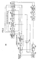
- FIG. 1 is a functional block diagram of a receiver according to a first embodiment of the present invention.
- the receiver 100 comprises a delay profile generator 102 which receives a signal which is transmitted by the OFDM method so as to generate a delay profile regarding the received signal.
- the output of the delay profile generator 102 is provided to the FFT 104 which performs FFT on the input signal.
- the portions which perform the serial-to-parallel conversion and the parallel-to-serial conversion related to the FFT process and the below IFFT (Inverse FFT) process are omitted.
- the receiver 100 comprises a demodulator 106, the demodulator 106 comprising a FFT 108 which performs FFT on the received signal and a channel compensation unit 110 which is connected to the FFT 108.
- the channel compensation unit 110 based on the information from the delay profile 102 which is obtained via the FFT 104 adjusts per sub-carrier the amplitude and the phase of the signal from the FFT 108 so as to output the demodulated signals.
- the receiver 100 comprises a hard-decision unit 112 which is connected to the demodulator 106, the hard-decision unit 112 making a hard-decision per sub-carrier on the signal point which is obtained from the demodulator 106.
- the receiver 100 comprises a replica generator 114 which is connected to the hard-decision unit 112.
- the replica generator 114 is connected to the hard-decision unit 112 and comprises an IFFT 116 which performs inverse FFT.
- the replica generator 114 comprises a received signal modifier 118 which is connected to the IFFT 116, the received signal modifier 118 comprising a suppression unit 120 which suppresses an interfering component within the received signal and an adder 122 which adds a predetermined signal component to the interference section having the interfering component included.
- the replica generator 114 comprises a FFT 124 which is connected to the received signal modifier 118 so as to perform FFT. Furthermore, the replica generator 114 comprises a channel compensation unit 126 which is connected to the FFT 124. An output of the channel compensation unit 126 is a replica signal per sub-carrier, the replica signal providing an output of the replica generator 114.
- the receiver 100 comprises an ICI suppression unit 128, the suppression unit 128 suppressing Inter-Carrier Interference (ICI) by adding the difference between the input and the output of the replica generator 114 to the demodulated signals from the demodulator 106.
- ICI Inter-Carrier Interference
- the receiver 100 comprises the hard-decision unit 130 which is connected to the ICI suppression unit 128 so as to make a hard decision per sub-carrier on the signal point.
- the receiver 100 comprises an IFFT 132 which is connected to the hard-decision unit 130 so as to perform IFFT.
- the receiver 100 comprises a delay unit 134 which is connected to the IFFT 132 so as to delay the input signal by one symbol period.
- the delay unit 134 is connected to the suppression unit 120 within the received signal modifier 118.
- the OFDM signal which is received at the receiver 100 is converted to a baseband signal via a wireless unit (not illustrated) so as to be input to the delay profile generator 102 after the removing of the guard interval.
- the delay profile generator 102 finds the timing, the amplitude (or the energy), and the phase of a preceding wave included in the received signal r and a plurality of delayed waves arriving with a delay relative to the preceding wave.
- the respective delayed waves are also called “multi-path components", or just "paths".
- the information regarding the delay profile (the timing, the amplitude and the phase) is provided to the received signal modifier 118 which performs processing in the time domain.
- the information regarding the delay profile is provided to the channel compensation units 110 and 126 after being further converted to information in the frequency domain at the FFT 104.
- the received signal includes only two paths and the delay time of the delayed wave relative to the preceding wave is longer than the length of the guard interval.
- the demodulated signals d-i are projected to be distorted relative to the original signals.
- the demodulated signals d-i are provided to the hard-decision unit 112 so that a hard decision is made per sub-carrier, the hard-decision unit 112 converting the respective demodulated signals d-i to hard-decision signals D-i.
- the hard-decision signals D-i are input to the IFFT 116 so as to be converted to the received signal in the time domain.
- the received signal in the time domain is modified at the received signal modifier 118.
- FIG. 2 is a diagram which illustrates a preceding wave 202 and a delayed wave 204 which are included in the received signal. Although the preceding wave 202 and the delayed wave 204 are depicted separately, the waves overlap to comprise the received signal. As illustrated in FIG. 2 , the kth OFDM symbols 206 and 208 which are the present demodulating targets, the preceding (k-1)th OFDM symbols 210 and 212, and the guard intervals 214 and 216 are depicted. The receiver receives a series of OFDM symbols so as to sequentially demodulate the OFDM symbols.
- the received signal which is affected by the inter-symbol interference is demodulated at the demodulator 106 so as to be output as the demodulated signals d-i.
- the demodulated signals d-i are provided with hard decisions at the hard-decision unit 112 so as to be output as the hard-decision signals D-i. For example, assuming the case of QPSK modulation in which the demodulated signal d-1 falls within the first quadrant of the signal constellation, the hard-decision signal D-1 will be a symbol which indicates (1,1).
- the hard-decision signals D-i are input to the IFFT 116 so as to be converted to the received signal in the time domain 216.
- the demodulation of the (k-1)th OFDM symbol will have been completed by the time the kth OFDM symbol is demodulated.
- the data of the (k-1)-th OFDM symbol is input to the hard-decision unit 130 per sub-carrier so as to be input to the IFFT 132 after the hard decision is made and to be input to the delay unit 134 which performs buffering for one symbol period. Therefore, by the time the kth OFDM symbol is demodulated, the (k-1)-th OFDM symbol will already have been demodulated and stored in the delay unit 134.
- the kth and the (k-1)-th received signals in the time domain are input.
- the suppression unit 120 based on the timing, the amplitude and the phase relative to the delayed wave from the delay profile generator 102, the signal component of the interference section S-I which causes interference at the time of the demodulation of the kth OFDM symbol is extracted from within the (k-1)-th OFDM symbol. Then, the timing, the amplitude, and the phase are adjusted so as to offset the signal component of the interference section S-I of the delayed wave which is included in the received signal in the time domain.
- the interference section S-I is the latter portion of the (k-1)-th OFDM symbol in the delayed wave, the length of the section corresponding to the duration which is derived by subtracting the length of the guard interval GI from the delay amount ⁇ of the delayed wave 204.
- the section having the length ⁇ (where ⁇ equals the delay amount of the delayed wave) which precedes the kth OFDM symbol in the delayed wave 204 is added to the signal from the suppression unit 120, while the timing, the amplitude, and the phase are adjusted so as to be made equal to S-k which is the latter portion of the kth OFDM symbol.
- the length of S-k is equal to ⁇ , the contents of the signal being equal to the tail-end portion of the kth OFDM symbol which is tentatively demodulated at the present.
- the received signal modifier 118 modifies a portion of the delayed wave 204 which is included in the received signal, the modification removing the interfering portion S-I of the (k-1)-th OFDM symbol so as to make the signal contents of the removed section S-I and those of the guard interval 216 portion equal to S-k.
- the guard interval 216 portion equals the tail-end section of the kth OFDM symbol
- the section in which the signal contents are actually modified at the received signal modifier 118 is the section corresponding to the interference portion S-I.
- the modified received signal will not include a signal component which causes inter-symbol interference with the kth OFDM symbol.
- the received signal which is modified at the received signal modifier 118 is provided to the FFT 124 so as to be input to the channel estimator 126 after being Fourier-transformed and to be output as the replica signal d-i per sub-carrier.
- the ICI suppression unit 128 After adding to the demodulated signals d-i the difference between the hard-decision signals D-i and the replica signals d-i, the ICI suppression unit 128 outputs the modified demodulated signal per sub-carrier.
- the output signal of the received signal modifier 118 includes the signal component regarding the preceding and the delayed waves, the signal component regarding the delayed wave modified for the kth OFDM symbol so as not to cause the inter-symbol interference.
- the output signal is Fourier-transformed at the FFT 124 so as to compensate for the transmission channel, the replica signal having no inter-symbol interference impact is obtained per sub-carrier.
- the impact of inter-carrier interference on the received signal ripples through all sub-carriers as it is white to the respective carriers (or the inter-carrier interference has no frequency selectivity). Therefore, the difference between the input and the output signals at the replica generator 114 becomes the signal which indicates the impact of the inter-symbol interference (inter-carrier interference) per sub-carrier.
- the removal of the difference from the demodulated signals d-i enables the obtaining of the demodulated signals with the inter-carrier interference suppressed.
- the output signals of the ICI suppression unit 128 are provided to a latter stage processor (not illustrated), and also to the hard-decision unit 130 in order to provide for the demodulation of the subsequent (k+1)th OFDM symbol.
- FIG. 3 illustrates a functional block diagram of a receiver according to a second embodiment of the present invention.
- the receiver 300 comprises the delay profile generator 302 which receives the OFDM signal so as to generate the delay profile.
- the delay profile generator 302 is connected to the FFT 304 which performs FFT. Besides, for brevity, the portions which perform the serial-parallel conversion and/or the parallel-to-serial conversion related to FFT or IFFT are omitted.
- the receiver 300 comprises the demodulator 306, the demodulator 306 comprising the FFT 308 which performs FFT and the channel compensation unit 310 which is connected to the FFT 308.
- the channel compensation unit 310 adjusts the amplitude and the phase of the output signals of the FFT 308 based on the delay profile so as to output the demodulated signal per sub-carrier.
- the receiver 300 comprises the hard-decision unit 312 which is connected to the demodulator 306, the hard-decision unit 312 making the hard decision per sub-carrier on the signal point which is obtained from the demodulator 306.
- the receiver 300 comprises the replica generator 314 which is connected to the hard-decision unit 312.
- the replica generator 314 comprises the IFFT 316 which is connected to the hard-decision unit 312 so as to perform inverse FFT.
- the replica generator 314 comprises the received signal modifier 318 which is connected to the IFFT 316, the received signal modifier 318 adding a predetermined signal component to the section in which the interfering component is included within the received signal.
- the replica generator 314 comprises the FFT 324 which is connected to the received signal modifier 318 so as to perform FFT.
- the replica generator 314 comprises the channel compensation unit 326 which is connected to the FFT 324.
- the outputs of the channel compensation unit 326 are adapted to be the outputs of the replica generator 314.
- the receiver 300 comprises the ICI suppression unit 328, the ICI suppression unit 328 suppressing the inter-carrier interference by adding to the demodulated signals from the demodulator 306 the difference between the inputs and the outputs of the replica generator 314.
- the receiver 300 comprises the hard-decision unit 330 which is connected to the ICI suppression unit 328 so as to make the hard decision per sub-carrier on the signal point.
- the receiver 300 comprises the IFFT 332 which is connected to the hard-decision unit 330 so as to perform inverse FFT.
- the receiver 300 comprises the delay unit 334 which is connected to the IFFT 332 so as to delay the input signal by one symbol period.
- the receiver 300 comprises an extraction unit 336 which extracts the inter-symbol interfering component, the extraction unit 336 extracting the already demodulated OFDM symbol from the delay unit 334 and, based on the information from the delay profile generator 302, the signal component of the interference section S-I which causes the inter-symbol interference.
- the receiver 300 comprises a suppression unit 338 which suppresses the inter-symbol interfering component included in the received signal, the suppression unit 338 combining the interfering component included in the received signal with the signal component which is extracted at the extraction unit 336 so as to offset the interfering component with the signal component, and providing the signal, with the interfering component removed, to the demodulator 308 at the latter stage.
- the OFDM signal which is received at the receiver 300 is input to the delay profile generator 302.
- the delay profile generator 302 detects the timing, the amplitude (or the energy) and the phase of the plurality of delayed waves which arrive with a delay relative to the preceding wave.
- the information regarding the delay profile (the timing, the amplitude, and the phase) is provided to the received signal modifier 318 and the extraction unit 336 which perform processing in the time domain.
- the information regarding the delay profile is also provided to the channel compensation units 310 and 326 after being converted to the information in the frequency domain at the FFT 304.
- the received signal contains only two paths and the delay time of the delayed wave relative to the preceding wave is longer than the length of the guard interval.
- the demodulation of the (k-1)th OFDM symbol will have been already completed by the time the kth symbol is demodulated.
- the respective data of the (k-1)th OFDM symbol are input to the hard-decision unit 330 per sub-carrier so as to have the hard decision made and then are input to the IFFT 332 and then to the delay unit 334 so as to perform the buffering for one symbol period. Therefore, by the time the kth OFDM symbol is demodulated, the demodulation of the (k-1)th OFDM symbol will already have been completed, and the results stored in the delay unit 334.
- the signal component of the interference section S-I which causes the interference at the time of demodulation of the kth OFDM symbol, from within the (k-1)th OFDM symbol based on the timing, the amplitude, and the phase relative to the delayed wave from the delay profile generator 302, is extracted (refer to FIG. 2 ).
- the suppression unit 338 combines the signals of the interfering portion of the delayed wave which is included in the received signal and of the interfering portion S-I which is extracted at the extraction unit 336 so as to offset the portions while adjusting the amplitude and the phase of the portions.
- the adjustment of the timing, the amplitude, and the phase for the combining may be performed either at the extraction unit 336 or at the timing of the combining at the suppression unit 338.
- the received signal, with the portion causing the inter-symbol interference within the delayed wave included in the received signal suppressed, is provided to the demodulator 306.
- the demodulated signals d-i are provided to the hard-decision unit 312 so as to have the hard decision per sub-carrier made, the hard-decision unit 312 converting the respective demodulated signals d-i to the hard-decision signals D-i.
- the hard-decision signals D-i are input to the IFFT 316 so as to be converted to the received signal in the time domain.
- the received signal in the time domain is further modified at the received signal modifier 318.
- the section having the length of ⁇ which precedes the kth OFDM symbol within the delayed wave 204 (in FIG. 2 ) is modified so as to be made equal to the latter portion S-k of the kth OFDM symbol.
- the length of S-k equals ⁇ , the contents of the signal being equal to the tail-end portion of the kth OFDM symbol which is tentatively demodulated at the present.
- the interfering portion S'-I regarding the (k-1)th OFDM symbol within the received signal has already been removed at the suppression unit 338.
- the received signal modifier 318 makes the signal contents of the removed section S-I and of the guard interval GI 216 portion equal to S-k.
- the guard interval 216 portion equals the tail-end portion of the OFDM symbol so that the section to which the actual modification of the signal contents is performed at the received signal modifier 318 is the section corresponding to the interfering portion S-I.
- the received signal which is modified at the received signal modifier 318 is provided to the FFT 324 so as to be Fourier-transformed and then input to the channel compensation unit 326 so as to be output as the replica signal d-i per sub-carrier.
- the ICI suppression unit 328 outputs per sub-carrier the modified demodulated signal by adding to the demodulated signals d-i the difference between the hard-decision signals D-i and the replica signals d-i. Similar to the first embodiment, the output signal of the received signal modifier 318 includes the signal component regarding the preceding and the delayed waves, the signal component of the delayed wave modified so as not to cause the inter-symbol interference with the kth OFDM symbol. When the output signal is Fourier-transformed at the FFT 324 so as to be compensated for the propagation channel, the replica signal having no impact of the inter-symbol interference is obtained per sub-carrier.
- the difference between the input and the output signals at the replica generator 314 becomes the signal which indicates the inter-symbol interference between sub-carriers (inter-carrier interference). Therefore, the removal of the difference from the demodulated signals d-i enables the obtaining of a demodulated signal with the inter-carrier interference suppressed.
- the output signal at the ICI suppression unit 328 is provided to a processor at the latter stage, not illustrated, and also to the hard-decision unit 330 in order to provide for the demodulation of the subsequent (k+1)th OFDM symbol.
- the provision of the extraction unit 336 and of the suppression unit 338 enables the removal, before the demodulation at the demodulator 306, of the signal contents of the interfering portion S-I that causes the inter-symbol interference from the delayed wave within the received signal. Therefore, the demodulated signal d-i from the demodulator 306 will have higher precision relative to the case of the first embodiment in which FFT, etc., are performed with the signal of the interference section S-I included in the received signal. This will enable the improvement in the accuracy of the hard-decision result at the hard-decision unit 312 so as to appropriately remove the inter-carrier interference.
- the signal level of the interfering section which is determined to cause interference (the section indicated as S-I) from the delayed wave within the received signal which is input to the demodulator 306 is made to be zero (by adding the signal from the extraction unit).
- the modified delayed wave will not cause as large an inter-symbol interference as in the case of the first embodiment
- the demodulated signal at the demodulator 306 becomes somewhat distorted by setting all of the time-sampled information to be zero. The distortion is suppressed at the ICI suppression unit 328.
- the suppression of the inter-carrier interference with precision higher than that in the first embodiment is enabled.
- the first embodiment is more advantageous than the second embodiment from the point of view of having a simpler configuration.
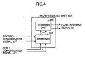
- FIG. 4 is a diagram illustrating a variation of a hard-decision unit.
- the hard-decision unit 402 may be used in lieu of the hard-decision units 112 and 130 of the first embodiment, or the hard-decision units 312 and 330 of the second embodiment.
- the hard-decision unit 402 comprises a combiner 404 which combines a first demodulated signal d-i(1) and a second demodulated signal d-i(2).
- the hard-decision unit 402 comprises the decision unit 406 which makes the hard decision per sub-carrier on the respective combined demodulated signals.
- such means for processing the received signal as those illustrated in FIG. 1 and in FIG. 3 are provided at the respective diversity branches.
- the demodulated signal at a certain diversity branch or the first demodulated signal d-i(1)
- the demodulated signal at another diversity branch or the second demodulated signal d-i(2)
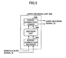
- FIG. 5 is a diagram which illustrates another variation of a hard-decision unit.
- the hard-decision unit 502 may be used in lieu of the hard-decision units 112 and 130 of the first embodiment, or the hard-decision units 312 and 330 of the second embodiment.
- the hard-decision unit 502 comprises, for the demodulated signal per sub-carrier, an error-correction decoder 504 which performs error-correction decoding, a decision unit 506 which makes the hard decision, and an error-correction coder 508 which performs error-correction coding.
- the hard decision is made after the error correction so as to enable the improvement in the precision of the hard decision.
- the hard decision is performed with high precision, even when the servicing transmission line is in an adverse environment, so as to enable the appropriate removal of the inter-carrier interference.
- FIG. 6 is a functional block diagram of a receiver according to a third embodiment of the present invention.
- the receiver 600 comprises the delay profile generator 602 which generates the delay profile of the OFDM signal with the guard interval removed.
- the output of the delay profile generator 602 is provided to the FFT 604 which performs the FFT.
- the receiver 600 comprises the demodulator 606, the demodulator 606 performing FFT on the received signal and channel compensation using the delay profile so as to output a first demodulated signal A.
- the receiver 600 comprises a first demodulated signal modifier 603, the first demodulated signal modifier 603 outputting a second demodulated signal B which modifies the first demodulated signal A.
- the receiver 600 comprises a second demodulated signal modifier 605, the second demodulated signal modifier 605 outputting a third demodulated signal C which modifies the second demodulated signal B.
- the receiver 600 comprises a third demodulated signal modifier 607, the third demodulated signal modifier 607 outputting a fourth demodulated signal D.
- the first through the third demodulated signal modifiers 603, 605, and 607 comprise similar configurations, only the configuration regarding the first demodulated signal modifier 603 is outlined.
- the first demodulated signal modifier 603, as in the first embodiment, comprises the hard-decision unit 612 which makes the hard decision per sub-carrier on the first demodulated signal A.
- the receiver 600 comprises the replica generator 614 which is connected to the hard-decision unit 612.
- the replica generator 614 comprises the IFFT 616 which is connected to the hard-decision unit 612 so as to perform IFFT.
- the replica generator 614 comprises the received signal modifier 618 which is connected to the IFFT 616, the received signal modifier 618 suppressing the interfering component within the received signal so as to add a predetermined signal component to the portion which has included the interfering component.
- the replica generator 614 comprises the FFT 624 which is connected to the received signal modifier 618 so as to perform FFT.
- the replica generator 614 comprises the channel compensation unit 626 which is connected to the FFT 624.
- the output of the channel compensation unit 626 is the replica signal per sub-carrier, adapting the output of the replica generator 614.
- the receiver 600 comprises the ICI suppression unit 628, the ICI suppression unit 628 suppressing the inter-carrier interference by adding per sub-carrier the difference between the inputs and the outputs of the replica generator 614 to the demodulated signals from the demodulator 606.
- the receiver 600 comprises the hard-decision unit 630 which is connected to the ICI suppression unit 628 so as to make the hard decision per carrier on the signal point.
- the receiver 600 comprises the IFFT 632 which is connected to the hard-decision unit 630 so as to perform inverse Fourier transform.
- the receiver 600 comprises the delay unit 634 which is connected to the IFFT 632 so as to delay the input signal by a predetermined period.
- the OFDM signal which is received at the receiver 600 is converted to a baseband signal via a wireless unit not illustrated so as to be input to the delay profile generator 602.
- the delay profile generator 602 determines the delay profile over a predetermined period.
- the information regarding the delay profile (the timing, the amplitude, and the phase) is provided to the received signal modifier 618 which performs processing in the time domain.
- the information regarding the delay profile is further converted to information in the frequency domain at the FFT 604 so as to be subsequently provided to the demodulator 606 and the channel compensation unit 626.
- the received signal is demodulated at the demodulator 606 so as to output the first demodulated signal A.
- the first demodulated signal A is provided to the hard-decision unit 612 so as to have the hard decision made per sub-carrier and to be converted to the hard-decision signal.
- the hard-decision signal is input to the IFFT 616 so as to be converted to the received signal in the time domain.
- the received signal in the time domain is modified at the received signal modifier 618.
- the demodulation of the OFDM symbols prior to and including the (k-1)th will have been completed by the time the kth OFDM symbol is demodulated.
- the respective data of the OFDM symbols prior to and including the (k-1)th symbol are input per sub-carrier to the hard-decision unit 630 so as to have the hard decision made and to be subsequently input to the IFFT 632 and to the delay unit 634 so as to perform the buffering for one symbol period.
- the kth and the (k-1)th received signals in the time domain are input.
- the signal component of the interference section S-I which will cause interference at the time of demodulation of the kth OFDM symbol is extracted from within the (k-1)th OFDM symbol.
- the signals are combined by adjusting the amplitude and the phase so as to offset the interfering portion S-I of the delayed wave which is included in the received signal in the time domain.
- the section having the length ⁇ which precedes the kth OFDM symbol 208 in the delayed wave 204 is modified by adjusting the timing, the amplitude, and the phase so as to equal the latter portion S-k of the kth OFDM symbol in the delayed wave 204.
- the received signal modifier 618 modifies a portion of the delayed wave 204 which is included in the received signal, the modification removing the interfering portion S-I of the (k-1)th OFDM symbol so as to make the signal contents of the removed section S-I and the guard interval GI 216 portion equal to S-k.
- the received signal which is modified at the received signal modifier 618 is provided to the FFT 624 so as to be Fourier-transformed and then input to the channel compensation unit 626 so as to be output per sub-carrier as the replica signals d-i.
- the first demodulated signal A is added to the difference between the hard-decision signals D-i and the replica signals d-i so as to output per carrier the modified demodulated signal.
- the output signal of the ICI suppression unit 628 is provided to the second demodulated signal modifier 605 as the second demodulation signal B.
- the second and the third demodulation signal modifiers 605 and 607 comprise similar elements so that eventually the output signal of the third demodulated signal modifier 607 is output as the fourth demodulated signal D.
- the fourth demodulated signal D is provided to the hard-decision unit 630 for subsequent processing.
- the first through the third demodulated signal modifiers 603 through 607 are provided so that processing such as the hard-decision processing on the demodulated signals, the generation of the replica signals, and the suppression of the inter-carrier interferences are repeated a plurality of times (three times in the present embodiment).
- processing such as the hard-decision processing on the demodulated signals, the generation of the replica signals, and the suppression of the inter-carrier interferences are repeated a plurality of times (three times in the present embodiment).
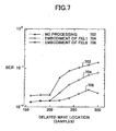
- FIG. 7 is a diagram which illustrates a simulation result according to the embodiments of the present invention.
- a time-invariant two-path model is adopted as a transmission line model, assuming an adverse propagation environment with a desired-undesired power ratio of 0 dB and a signal-to-noise ratio of 20 dB.
- the phase difference of the delayed wave relative to the preceding wave is assumed to be 30 degrees. It is assumed that the number of sub-carriers is 1,024 and that one OFDM symbol comprises 1,224 symbols (of which 200 samples are allocated to the guard interval).
- the pilot symbol spacing of 16 symbols and the modulation method of 16-QAM are assumed.
- the vertical axis illustrates the Bit Error Rate (BER), while the horizontal axis illustrates the delay amount of the delayed wave relative to the preceding wave.
- the graph 702 illustrates the BER characteristics in the case of modulating without performing the processing according to the embodiment of the present invention.
- the graph 704 illustrates the BER characteristics in the case of performing the processing according to the embodiment as illustrated in FIG. 3 .
- the graph 706 illustrates the BER characteristics in the case of performing the processing according to the embodiment as illustrated in FIG. 6 (where the number of repetitions is five).
- the BER for the section in which the delayed wave covers up to 200 samples only shows a very small value of about 10 -2 .
- the BER will degrade.
- graphs 704 and 706 it is understood that the repetitious modification of the demodulated signal provides a good BER.
- the hard-decision process is performed in the embodiments of the present invention, the hard-decision process is performed for evaluating the inter-carrier interference component which is included in the demodulated signal d-i, the demodulated signal with the inter-carrier interference removed (the output of the ICI suppression unit) having the soft-decision information maintained.
- the modification at the received signal modifiers 118, 318, and 618 using the received signal in the time domain which is reconstructed based on the result of the tentative demodulation at the demodulators 106, 306, and 606 is performed, it is also possible to perform modification using other signals. For example, it is possible to perform the modulation using a known signal which is received for each of a predetermined number of OFDM symbols. The use of the known signals at the transmitting and the receiving ends enables the modification of the received signal at higher precision.
- the embodiments of the present invention assume that the contents of the already demodulated OFDM symbol that precedes the target OFDM symbol to be demodulated, are correct.
Claims (12)
- Ein Empfänger (100) zum Demodulieren eines Orthogonal-Frequenz-Multiplex-Symbols, das durch ein Orthogonal-Frequenz-Multiplex-Verfahren bzw. Multicarrier-Modulationsverfahren übertragen wird, umfassend:eine Verzögerungsprofilerzeugungseinheit (102), die angeordnet ist zum Erzeugen eines Verzögerungsprofils hinsichtlich einer vorangehenden Welle und einer verzögerten Welle, die in einem empfangenen Signal enthalten sind;eine Demodulierungseinheit (106), die angeordnet ist zum Demodulieren des empfangenen Signals, um ein demoduliertes Signal pro Unterträger auszugeben;eine Harte-Entscheidung-Einheit (112), die angeordnet ist zum Durchführen einer harten Entscheidung pro Unterträger bei einem Signalpunkt basierend auf dem demodulierten Signal, um ein Harte-Entscheidung-Signal auszugeben;eine Replik-Erzeugungseinheit (114), die angeordnet ist zum Verwenden des Harte-Entscheidung-Signals, um eine Replik-Signal pro Unterträger zu erzeugen; undeine Intra-Träger-Interferenz-Unterdrückungseinheit (128), die angeordnet ist zum Hinzufügen einer Differenz zwischen dem Harte-Entscheidung-Signal und dem Replik-Signal zu dem demodulierten Signal, um eine Intra-Träger-Interferenz zu unterdrücken, und die die Addition ausgibt;wobei die Replik-Erzeugungseinheit (114) folgendes umfasst:eine Zeitbereichs-Empfangssignal-Erzeugungseinheit (116), die angeordnet ist zum inversen Fourier-Transformieren des Harte-Entscheidung-Signals, um ein empfangenes Signal im Zeitbereich zu erzeugen;eine Signalkomponentenunterdrückungseinheit (120), die angeordnet ist zum Unterdrücken, durch Verwenden eines vorangehenden Symbols, das ein bereits demoduliertes Symbol ist, das einem Ziel-Demodulationssymbol vorangeht, das ein zu demodulierendes OFDM-Symbol ist, einer Signalkomponente des vorangehenden Symbols, das in der verzögerten Welle enthalten ist;ein Empfangssymbol-Modifizierer (118) zum Erzeugen eines modifizierten empfangenen Symbols, der angeordnet ist zum Hinzufügen, vor dem Ziel-Demodulationssymbol in der verzögerten Welle, eines Teils des empfangenen Signals in dem Zeitbereich; undeine Transformationssignalerzeugungseinheit (124, 126), die angeordnet ist zum Erzeugen des Replik-Signals durch Fourier-Transformieren des modifizierten empfangenen Signals und zum Anpassen pro Unterträger der Amplitude und der Phase des Fourier-Transformierten Signals basierend auf dem Verzögerungsprofil, um die demodulierten Signale auszugeben,wobei der Empfangssignal-Modifizierer (118) die Signalkomponentenunterdrückungseinheit (120) umfasst.
- Der Empfänger (100) nach Anspruch 1, wobei die Harte-Entscheidung-Einheit (112) angepasst ist zum Durchführen der harten Entscheidung pro Unterträger bei dem Signalpunkt basierend auf einem Signal durch Kombinieren des demodulierten Signals, das ein demoduliertes Signal ist, das von einem Zweig einer Mehrfachantenne empfangen wird, und des demodulierten Signals, das ein demoduliertes Signal ist, das von einem anderen Mehrfachzweig empfangen wird, um das Harte-Entscheidung-Signal auszugeben.
- Der Empfänger (100) nach Anspruch 1, wobei die Harte-Entscheidung-Einheit (112) folgendes umfasst:eine Decodierungseinheit (504), die angeordnet ist zum fehlerkorrigierten Dekodieren des demodulierten Signals;eine Entscheidungseinheit (506), die angeordnet ist zum Durchführen der harten Entscheidung pro Unterträger bei einem fehlerkorrigierten dekodierten Signalpunkt; und eine Ausgabeeinheit (508), die angeordnet ist zum fehlerkorrigierten Decodieren des Harte-Entscheidung-Ergebnisses, um das Harte-Entscheidung-Signal auszugeben.
- Der Empfänger (600) nach Anspruch 1, ferner umfassend eine mehrstufige Verarbeitungsroute (603, 605, 607), die angeordnet ist zum Durchführen einer Serie von Verarbeitungen, wobei jede Verarbeitung Erzeugung eines Harte-Entscheidung-Signals, Erzeugung des Replik-Signals und Unterdrückung der Intra-Träger-Interferenz umfasst.
- Der Empfänger (100) nach Anspruch 1, ferner umfassend einen Empfangssignal-Modifizierer (118), der angeordnet ist zum weiteren Hinzufügen eines Teils eines bekannten Signals, das pro vorbestimmter Anzahl von OFDM-Symbolen empfangen wird, vor dem demodulierten Symbol der verzögerten Welle, um das modifizierte Empfangssignal zu erzeugen.
- Der Empfänger (100) nach Anspruch 1, angeordnet zum Modifizieren des empfangenen Signals, um Signalinhalte eines Teils, der dem Ziel-Demodulierungs-Symbol vorangeht, das in der verzögerten Welle enthalten ist, dem Teil des empfangenen Signals in dem Zeitbereich anzugleichen.
- Ein Empfänger (300), der angeordnet ist zum Demodulieren eines Orthogonal-Frequenz-Multiplex-Symbols, das durch ein Orthogonal-Frequenz-Multiplex-Verfahren bzw. Multicarrier-Modulationsverfahren übertragen wird, umfassend:eine Verzögerungsprofilerzeugungseinheit (302), die angeordnet ist zum Erzeugen eines Verzögerungsprofils hinsichtlich einer vorangehenden Welle und einer verzögerten Welle, die in einem empfangenen Signal enthalten sind;eine Signalkomponentenunterdrückungseinheit (338), die angeordnet ist zum Unterdrücken, durch Verwenden eines vorangehenden Symbols, das ein bereits demoduliertes Symbol ist, das einem Ziel-Demodulationssymbol vorangeht, das ein zu demodulierendes OFDM-Symbol ist, einer Signalkomponente des vorangehenden Symbols, das in der verzögerten Welle enthalten ist;eine Demodulierungseinheit (306), die angeordnet ist zum Demodulieren des empfangenen Signals, um ein demoduliertes Signal pro Unterträger auszugeben;eine Harte-Entscheidung-Einheit (312), die angeordnet ist zum Durchführen einer harten Entscheidung pro Unterträger bei einem Signalpunkt basierend auf dem demodulierten Signal, um ein Harte-Entscheidung-Signal auszugeben;eine Replik-Erzeugungseinheit (314), die angeordnet ist zum Verwenden des Harte-Entscheidung-Signals, um eine Replik-Signal-pro Unterträger zu erzeugen; undeine Intra-Träger-Interferenz-Unterdrückungseinheit (328), die angeordnet ist zum Hinzufügen einer Differenz zwischen dem Harte-Entscheidung-Signal und dem Replik-Signal zu dem demodulierten Signal, um eine Intra-Träger-Interferenz zu unterdrücken, und die die Addition ausgibt;wobei die Replik-Erzeugungseinheit (314) folgendes umfasst:eine Zeitbereichs-Empfangssignal-Erzeugungseinheit (316), die angeordnet ist zum inversen Fourier-Transformieren des Harte-Entscheidung-Signals, um ein empfangenes Signal im Zeitbereich zu erzeugen;ein Empfangssymbol-Modifizierer (318) zum Erzeugen eines modifizierten empfangenen Symbols, der angeordnet ist zum Hinzufügen, vor dem Ziel-Demodulationssymbol in der verzögerten Welle, eines Teils des empfangenen Signals in dem Zeitbereich; undeine Transformationssignalerzeugungseinheit (324, 326), die angeordnet ist zum Erzeugen des Replik-Signals durch Fourier-Transformieren des modifizierten empfangenen Signals und zum Anpassen pro Unterträger der Amplitude und der Phase des Fourier-Transformierten Signals basierend auf dem Verzögerungsprofil, um die demodulierten Signale auszugeben.
- Der Empfänger (300) nach Anspruch 7, wobei die Harte-Entscheidung-Einheit (312) angepasst ist zum Durchführen der harten Entscheidung pro Unterträger bei dem Signalpunkt basierend auf einem Signal durch Kombinieren des demodulierten Signals, das ein demoduliertes Signal ist, das von einem Zweig einer Mehrfachantenne empfangen wird, und des demodulierten Signals, das ein demoduliertes Signal ist, das von einem anderen Mehrfachzweig empfangen wird, um das Harte-Entscheidung-Signal auszugeben.
- Der Empfänger (300) nach Anspruch 7, wobei die Harte-Entscheidung-Einheit folgendes umfasst:eine Decodierungseinheit (504), die angeordnet ist zum fehlerkorrigierten Dekodieren des demodulierten Signals;eine Entscheidungseinheit (506), die angeordnet ist zum Durchführen der harten Entscheidung pro Unterträger bei einem fehlerkorrigierten dekodierten Signalpunkt; und eine Ausgabeeinheit (508), die angeordnet ist zum fehlerkorrigierten Decodieren des Harte-Entscheidung-Ergebnisses, um das Harte-Entscheidung-Signal auszugeben.
- Der Empfänger (600) nach Anspruch 7, ferner umfassend eine mehrstufige Verarbeitungsroute (603, 605, 607), die angeordnet ist zum Durchführen einer Serie von Verarbeitungen, umfassend die Erzeugung eines Harte-Entscheidung-Signals, die Erzeugung des Replik-Signals und die Unterdrückung der Intra-Träger-Interferenz umfasst.
- Der Empfänger (300) nach Anspruch 7, ferner umfassend einen Empfangssignal-Modifizierer, der angeordnet ist zum weiteren Hinzufügen, vor dem demodulierten Symbol in der verzögerten Welle, eines Teils eines bekannten Signals, das pro vorbestimmter Anzahl von OFDM-Symbolen empfangen wird.
- Der Empfänger (300) nach Anspruch 7, angeordnet zum Modifizieren des empfangenen Signals, um Signalinhalte eines Teils, der dem Ziel-Demodulierungs-Symbol vorangeht, das in der verzögerten Welle enthalten ist, dem Teil des empfangenen Signals in dem Zeitbereich anzugleichen.
Applications Claiming Priority (2)
| Application Number | Priority Date | Filing Date | Title |
|---|---|---|---|
| JP2003078717A JP4121407B2 (ja) | 2003-03-20 | 2003-03-20 | Ofdmシンボルを復調する受信機 |
| JP2003078717 | 2003-03-20 |
Publications (3)
| Publication Number | Publication Date |
|---|---|
| EP1478149A2 EP1478149A2 (de) | 2004-11-17 |
| EP1478149A3 EP1478149A3 (de) | 2007-09-19 |
| EP1478149B1 true EP1478149B1 (de) | 2009-01-28 |
Family
ID=32984880
Family Applications (1)
| Application Number | Title | Priority Date | Filing Date |
|---|---|---|---|
| EP04004056A Expired - Fee Related EP1478149B1 (de) | 2003-03-20 | 2004-02-23 | Mehrträgerempfänger |
Country Status (4)
| Country | Link |
|---|---|
| US (1) | US7313189B2 (de) |
| EP (1) | EP1478149B1 (de) |
| JP (1) | JP4121407B2 (de) |
| DE (1) | DE602004019262D1 (de) |
Families Citing this family (41)
| Publication number | Priority date | Publication date | Assignee | Title |
|---|---|---|---|---|
| JP2005269392A (ja) * | 2004-03-19 | 2005-09-29 | Nec Electronics Corp | 受信装置及び受信方法と通信システムと装置 |
| JP4421416B2 (ja) * | 2004-08-04 | 2010-02-24 | 富士通株式会社 | Ofdm方式の受信装置 |
| JP4167646B2 (ja) | 2004-11-30 | 2008-10-15 | 株式会社東芝 | Ofdm復調装置 |
| KR100705444B1 (ko) | 2004-12-21 | 2007-04-09 | 한국전자통신연구원 | Hpi 시스템에서의 ici 신호 제거 방법 및 그 장치 |
| US7512197B2 (en) * | 2005-02-07 | 2009-03-31 | Harris Corporation | System and method for removing interfering narrowband signals from wide bandwidth receive signal |
| JP4440303B2 (ja) | 2005-03-02 | 2010-03-24 | 三菱電機株式会社 | 受信装置 |
| US7706428B2 (en) * | 2005-04-21 | 2010-04-27 | Telefonaktiebolaget L M Ericsson (Publ) | Low complexity inter-carrier interference cancellation |
| JP4936680B2 (ja) | 2005-05-20 | 2012-05-23 | 富士通株式会社 | Ofdm受信方法及び受信装置 |
| US7426199B2 (en) * | 2005-06-29 | 2008-09-16 | Intel Corporation | Wireless communication device and method for reducing carrier frequency offsets over a simultaneous multi-user uplink in a multicarrier communication network |
| US7480497B2 (en) * | 2005-06-29 | 2009-01-20 | Intel Corporation | Multicarrier receiver and method for carrier frequency offset correction and channel estimation for receipt of simultaneous transmissions over a multi-user uplink |
| US7706248B2 (en) * | 2005-06-29 | 2010-04-27 | Intel Corporation | Multicarrier receiver and method for time-delay compensation in a multi-user uplink |
| US8611305B2 (en) | 2005-08-22 | 2013-12-17 | Qualcomm Incorporated | Interference cancellation for wireless communications |
| US9071344B2 (en) | 2005-08-22 | 2015-06-30 | Qualcomm Incorporated | Reverse link interference cancellation |
| EP1921785A1 (de) * | 2005-08-26 | 2008-05-14 | Sharp Kabushiki Kaisha | Kommunikationssteuervorrichtung, kommunikationsendgerätevorrichtung, drahtloses kommunikationssystem und sendeverfahren |
| CN101341677B (zh) * | 2005-10-21 | 2012-01-11 | 松下电器产业株式会社 | 载波间干涉去除装置及使用其的接收装置 |
| KR100752670B1 (ko) | 2006-08-25 | 2007-08-29 | 삼성전자주식회사 | 순방향 에러 정정 디코더의 출력을 이용하여 심볼 값을추정하는 ofdm 시스템, 심볼 추정 장치 및 캐리어사이의 간섭 제거 방법 |
| US7830994B2 (en) * | 2006-10-18 | 2010-11-09 | Analog Devices, Inc. | Channel estimation system and method |
| WO2008066270A1 (en) * | 2006-12-01 | 2008-06-05 | Electronics And Telecommunications Research Institute | Iterative reception method and iterative receiver |
| WO2008155947A1 (ja) * | 2007-06-19 | 2008-12-24 | Sharp Kabushiki Kaisha | 受信機及び受信方法 |
| US7711031B2 (en) * | 2007-06-22 | 2010-05-04 | Newport Media, Inc. | Adaptive technique for inter-carrier-interference canceling in OFDM systems |
| JP5030311B2 (ja) * | 2007-06-26 | 2012-09-19 | シャープ株式会社 | 受信機、受信方法および集積回路 |
| CN101141228B (zh) * | 2007-09-19 | 2011-11-30 | 中兴通讯股份有限公司 | 一种在sdh数据流中并行插入开销字节的装置及方法 |
| JP5314002B2 (ja) * | 2008-02-27 | 2013-10-16 | パナソニック株式会社 | 受信装置、集積回路及び受信方法 |
| US8831063B2 (en) * | 2008-03-18 | 2014-09-09 | Qualcomm Incorporated | Single carrier burst structure for decision feedback equalization and tracking |
| US20100046660A1 (en) | 2008-05-13 | 2010-02-25 | Qualcomm Incorporated | Interference cancellation under non-stationary conditions |
| US8995417B2 (en) | 2008-06-09 | 2015-03-31 | Qualcomm Incorporated | Increasing capacity in wireless communication |
| US8787440B2 (en) * | 2008-07-25 | 2014-07-22 | Qualcomm Incorporated | Determination of receive data values |
| US9277487B2 (en) * | 2008-08-01 | 2016-03-01 | Qualcomm Incorporated | Cell detection with interference cancellation |
| US9237515B2 (en) | 2008-08-01 | 2016-01-12 | Qualcomm Incorporated | Successive detection and cancellation for cell pilot detection |
| US8509293B2 (en) * | 2008-08-19 | 2013-08-13 | Qualcomm Incorporated | Semi-coherent timing propagation for GERAN multislot configurations |
| DE102009017552B3 (de) * | 2009-04-17 | 2010-09-30 | Sew-Eurodrive Gmbh & Co. Kg | Vorrichtung und Verfahren zur berührungslosen Übertragung elektrischer Leistung und Information |
| EP2244432A1 (de) * | 2009-04-24 | 2010-10-27 | Vodafone Holding GmbH | Kompensation von Trägerfrequenzoffsets in OFDM Systemen |
| US9160577B2 (en) | 2009-04-30 | 2015-10-13 | Qualcomm Incorporated | Hybrid SAIC receiver |
| US8787509B2 (en) | 2009-06-04 | 2014-07-22 | Qualcomm Incorporated | Iterative interference cancellation receiver |
| US8619928B2 (en) * | 2009-09-03 | 2013-12-31 | Qualcomm Incorporated | Multi-stage interference suppression |
| US8831149B2 (en) | 2009-09-03 | 2014-09-09 | Qualcomm Incorporated | Symbol estimation methods and apparatuses |
| US9509452B2 (en) | 2009-11-27 | 2016-11-29 | Qualcomm Incorporated | Increasing capacity in wireless communications |
| KR101363016B1 (ko) | 2009-11-27 | 2014-02-13 | 퀄컴 인코포레이티드 | 무선 통신들에서의 용량 증가 |
| US8335269B2 (en) * | 2009-12-16 | 2012-12-18 | Electronics And Telecommunications Research Institute | Apparatus for receiving signals in a communication system based on multicarrier transmission and method for interference cancellation |
| US8396440B2 (en) * | 2010-06-22 | 2013-03-12 | Qualcomm Incorporated | Signal reception method and apparatus for non-stationary channels |
| DE112011105861T5 (de) * | 2011-11-18 | 2014-08-21 | Intel Corporation | Störungsunterdrückung zwischen Trägern für Empfänger in orthogonalen Frequenzmultiplex |
Family Cites Families (3)
| Publication number | Priority date | Publication date | Assignee | Title |
|---|---|---|---|---|
| JP2934225B1 (ja) * | 1998-04-06 | 1999-08-16 | 株式会社次世代デジタルテレビジョン放送システム研究所 | Ofdm復調装置 |
| US6928120B1 (en) * | 2000-09-25 | 2005-08-09 | Cingular Wireless Ii, Llc | Methods and apparatus for use in reducing residual phase error in OFDM communication signals |
| JP4298320B2 (ja) * | 2002-11-08 | 2009-07-15 | 富士通株式会社 | Ofdm伝送方式における受信装置 |
-
2003
- 2003-03-20 JP JP2003078717A patent/JP4121407B2/ja not_active Expired - Fee Related
-
2004
- 2004-02-23 US US10/784,437 patent/US7313189B2/en not_active Expired - Fee Related
- 2004-02-23 DE DE602004019262T patent/DE602004019262D1/de not_active Expired - Lifetime
- 2004-02-23 EP EP04004056A patent/EP1478149B1/de not_active Expired - Fee Related
Also Published As
| Publication number | Publication date |
|---|---|
| JP2004289475A (ja) | 2004-10-14 |
| EP1478149A3 (de) | 2007-09-19 |
| US7313189B2 (en) | 2007-12-25 |
| DE602004019262D1 (de) | 2009-03-19 |
| EP1478149A2 (de) | 2004-11-17 |
| US20040184550A1 (en) | 2004-09-23 |
| JP4121407B2 (ja) | 2008-07-23 |
Similar Documents
| Publication | Publication Date | Title |
|---|---|---|
| EP1478149B1 (de) | Mehrträgerempfänger | |
| JP4936680B2 (ja) | Ofdm受信方法及び受信装置 | |
| JP4189477B2 (ja) | Ofdm(直交周波数分割多重)適応等化受信方式及び受信機 | |
| JP2006262039A (ja) | 伝搬路推定方法及び伝搬路推定装置 | |
| JPWO2006137375A1 (ja) | マルチキャリア伝送方式の送信装置及び受信装置並びにマルチキャリア伝送方式を用いた送信方法及び受信方法 | |
| EP2192735A1 (de) | Empfangsvorrichtung und Verfahren zum Empfangen von Signalen in einem drahtlosen Kommunikationssystem mit verbesserter Entzerrungsleistung | |
| US20050190800A1 (en) | Method and apparatus for estimating noise power per subcarrier in a multicarrier system | |
| US20080118012A1 (en) | Method and apparatus for interference cancellation in a wireless communication system | |
| EP1335518A1 (de) | Empfang Mehrträger-Spreizspekturmsignale | |
| JP2005198223A (ja) | マルチキャリアにおけるパケット伝送用マルチユーザ検出受信機 | |
| US20070133393A1 (en) | Multi-carrier receiving method and multi-carrier receiving apparatus | |
| JP2005143115A (ja) | 多重アンテナを使用する直交周波数分割多重システムでの干渉信号を除去する装置及び方法 | |
| Jiang et al. | Performance evaluation of four orthogonal single sideband elements modulation scheme in multi-carrier transmission systems | |
| Yeh et al. | New parallel algorithm for mitigating the frequency offset of OFDM systems | |
| JP7215910B2 (ja) | Mmse等化受信装置 | |
| CN115277334B (zh) | 高速移动环境下otsm系统的mrc迭代均衡方法 | |
| Pereira et al. | Tibwb-ofdm: A promising modulation technique for mimo 5g transmissions | |
| Dinis et al. | Joint detection and channel estimation for block transmission schemes | |
| Ogundile et al. | Improved reliability information for OFDM systems on time-varying frequency-selective fading channels | |
| Obara et al. | BLER of Turbo SIC Multiplying Weighting Factor to Symbol Estimates for OFDM Using FTN Signaling | |
| Kalra et al. | Inter carrier interference analysis of scfdma system using frequency domain equalization | |
| JP2008263571A (ja) | 局部発振位相雑音抑圧送受信機 | |
| Shobudani et al. | Faster-than-Nyquist Signaling Assigning Increased Resources to Parity Bits for Turbo-Coded OFDM | |
| Shobudani et al. | TDM Based Reference Signal Multiplexing for OFDM Using Faster-than-Nyquist Signaling | |
| Coelho et al. | Efficient channel estimation for OFDM and SC-FDE schemes |
Legal Events
| Date | Code | Title | Description |
|---|---|---|---|
| PUAI | Public reference made under article 153(3) epc to a published international application that has entered the european phase |
Free format text: ORIGINAL CODE: 0009012 |
|
| AK | Designated contracting states |
Kind code of ref document: A2 Designated state(s): AT BE BG CH CY CZ DE DK EE ES FI FR GB GR HU IE IT LI LU MC NL PT RO SE SI SK TR |
|
| AX | Request for extension of the european patent |
Extension state: AL LT LV MK |
|
| PUAL | Search report despatched |
Free format text: ORIGINAL CODE: 0009013 |
|
| AK | Designated contracting states |
Kind code of ref document: A3 Designated state(s): AT BE BG CH CY CZ DE DK EE ES FI FR GB GR HU IE IT LI LU MC NL PT RO SE SI SK TR |
|
| AX | Request for extension of the european patent |
Extension state: AL LT LV MK |
|
| 17P | Request for examination filed |
Effective date: 20071122 |
|
| 17Q | First examination report despatched |
Effective date: 20080118 |
|
| AKX | Designation fees paid |
Designated state(s): DE FR GB |
|
| GRAP | Despatch of communication of intention to grant a patent |
Free format text: ORIGINAL CODE: EPIDOSNIGR1 |
|
| GRAS | Grant fee paid |
Free format text: ORIGINAL CODE: EPIDOSNIGR3 |
|
| GRAA | (expected) grant |
Free format text: ORIGINAL CODE: 0009210 |
|
| RAP1 | Party data changed (applicant data changed or rights of an application transferred) |
Owner name: FUJITSU LIMITED |
|
| RIN1 | Information on inventor provided before grant (corrected) |
Inventor name: ISHIZU, EIZOU C/O FUJITSU LIMITED Inventor name: YOSHIDA, MAKOTO, C/O FUJITSU LIMITED |
|
| AK | Designated contracting states |
Kind code of ref document: B1 Designated state(s): DE FR GB |
|
| REG | Reference to a national code |
Ref country code: GB Ref legal event code: FG4D |
|
| REF | Corresponds to: |
Ref document number: 602004019262 Country of ref document: DE Date of ref document: 20090319 Kind code of ref document: P |
|
| PLBE | No opposition filed within time limit |
Free format text: ORIGINAL CODE: 0009261 |
|
| STAA | Information on the status of an ep patent application or granted ep patent |
Free format text: STATUS: NO OPPOSITION FILED WITHIN TIME LIMIT |
|
| 26N | No opposition filed |
Effective date: 20091029 |
|
| PGFP | Annual fee paid to national office [announced via postgrant information from national office to epo] |
Ref country code: DE Payment date: 20110216 Year of fee payment: 8 Ref country code: FR Payment date: 20110218 Year of fee payment: 8 |
|
| PGFP | Annual fee paid to national office [announced via postgrant information from national office to epo] |
Ref country code: GB Payment date: 20110223 Year of fee payment: 8 |
|
| GBPC | Gb: european patent ceased through non-payment of renewal fee |
Effective date: 20120223 |
|
| REG | Reference to a national code |
Ref country code: FR Ref legal event code: ST Effective date: 20121031 |
|
| REG | Reference to a national code |
Ref country code: DE Ref legal event code: R119 Ref document number: 602004019262 Country of ref document: DE Effective date: 20120901 |
|
| PG25 | Lapsed in a contracting state [announced via postgrant information from national office to epo] |
Ref country code: GB Free format text: LAPSE BECAUSE OF NON-PAYMENT OF DUE FEES Effective date: 20120223 Ref country code: FR Free format text: LAPSE BECAUSE OF NON-PAYMENT OF DUE FEES Effective date: 20120229 |
|
| PG25 | Lapsed in a contracting state [announced via postgrant information from national office to epo] |
Ref country code: DE Free format text: LAPSE BECAUSE OF NON-PAYMENT OF DUE FEES Effective date: 20120901 |