EP1477660A1 - Lagerdeckelanordnung für ein Kurbelwellenlager - Google Patents
Lagerdeckelanordnung für ein Kurbelwellenlager Download PDFInfo
- Publication number
- EP1477660A1 EP1477660A1 EP03101341A EP03101341A EP1477660A1 EP 1477660 A1 EP1477660 A1 EP 1477660A1 EP 03101341 A EP03101341 A EP 03101341A EP 03101341 A EP03101341 A EP 03101341A EP 1477660 A1 EP1477660 A1 EP 1477660A1
- Authority
- EP
- European Patent Office
- Prior art keywords
- bearing
- crankshaft
- cylinder block
- caps
- internal combustion
- Prior art date
- Legal status (The legal status is an assumption and is not a legal conclusion. Google has not performed a legal analysis and makes no representation as to the accuracy of the status listed.)
- Granted
Links
- 238000002485 combustion reaction Methods 0.000 claims abstract description 20
- OKTJSMMVPCPJKN-UHFFFAOYSA-N Carbon Chemical compound [C] OKTJSMMVPCPJKN-UHFFFAOYSA-N 0.000 claims description 6
- 229910001018 Cast iron Inorganic materials 0.000 claims description 6
- 229910001141 Ductile iron Inorganic materials 0.000 claims description 6
- 229910000831 Steel Inorganic materials 0.000 claims description 5
- XAGFODPZIPBFFR-UHFFFAOYSA-N aluminium Chemical compound [Al] XAGFODPZIPBFFR-UHFFFAOYSA-N 0.000 claims description 5
- 229910052782 aluminium Inorganic materials 0.000 claims description 5
- 229910002804 graphite Inorganic materials 0.000 claims description 5
- 239000010439 graphite Substances 0.000 claims description 5
- 239000010959 steel Substances 0.000 claims description 5
- 229910000838 Al alloy Inorganic materials 0.000 claims description 3
- 239000000463 material Substances 0.000 description 7
- 229910045601 alloy Inorganic materials 0.000 description 1
- 239000000956 alloy Substances 0.000 description 1
- 230000005540 biological transmission Effects 0.000 description 1
- 230000001427 coherent effect Effects 0.000 description 1
- 230000008878 coupling Effects 0.000 description 1
- 238000010168 coupling process Methods 0.000 description 1
- 238000005859 coupling reaction Methods 0.000 description 1
- 230000000694 effects Effects 0.000 description 1
- 230000005284 excitation Effects 0.000 description 1
- 230000000630 rising effect Effects 0.000 description 1
Images
Classifications
-
- F—MECHANICAL ENGINEERING; LIGHTING; HEATING; WEAPONS; BLASTING
- F02—COMBUSTION ENGINES; HOT-GAS OR COMBUSTION-PRODUCT ENGINE PLANTS
- F02F—CYLINDERS, PISTONS OR CASINGS, FOR COMBUSTION ENGINES; ARRANGEMENTS OF SEALINGS IN COMBUSTION ENGINES
- F02F7/00—Casings, e.g. crankcases
- F02F7/0065—Shape of casings for other machine parts and purposes, e.g. utilisation purposes, safety
- F02F7/008—Sound insulation
-
- F—MECHANICAL ENGINEERING; LIGHTING; HEATING; WEAPONS; BLASTING
- F02—COMBUSTION ENGINES; HOT-GAS OR COMBUSTION-PRODUCT ENGINE PLANTS
- F02F—CYLINDERS, PISTONS OR CASINGS, FOR COMBUSTION ENGINES; ARRANGEMENTS OF SEALINGS IN COMBUSTION ENGINES
- F02F7/00—Casings, e.g. crankcases
- F02F7/0043—Arrangements of mechanical drive elements
- F02F7/0053—Crankshaft bearings fitted in the crankcase
-
- F—MECHANICAL ENGINEERING; LIGHTING; HEATING; WEAPONS; BLASTING
- F16—ENGINEERING ELEMENTS AND UNITS; GENERAL MEASURES FOR PRODUCING AND MAINTAINING EFFECTIVE FUNCTIONING OF MACHINES OR INSTALLATIONS; THERMAL INSULATION IN GENERAL
- F16C—SHAFTS; FLEXIBLE SHAFTS; ELEMENTS OR CRANKSHAFT MECHANISMS; ROTARY BODIES OTHER THAN GEARING ELEMENTS; BEARINGS
- F16C17/00—Sliding-contact bearings for exclusively rotary movement
- F16C17/12—Sliding-contact bearings for exclusively rotary movement characterised by features not related to the direction of the load
- F16C17/22—Sliding-contact bearings for exclusively rotary movement characterised by features not related to the direction of the load with arrangements compensating for thermal expansion
-
- F—MECHANICAL ENGINEERING; LIGHTING; HEATING; WEAPONS; BLASTING
- F16—ENGINEERING ELEMENTS AND UNITS; GENERAL MEASURES FOR PRODUCING AND MAINTAINING EFFECTIVE FUNCTIONING OF MACHINES OR INSTALLATIONS; THERMAL INSULATION IN GENERAL
- F16C—SHAFTS; FLEXIBLE SHAFTS; ELEMENTS OR CRANKSHAFT MECHANISMS; ROTARY BODIES OTHER THAN GEARING ELEMENTS; BEARINGS
- F16C9/00—Bearings for crankshafts or connecting-rods; Attachment of connecting-rods
- F16C9/02—Crankshaft bearings
-
- F—MECHANICAL ENGINEERING; LIGHTING; HEATING; WEAPONS; BLASTING
- F02—COMBUSTION ENGINES; HOT-GAS OR COMBUSTION-PRODUCT ENGINE PLANTS
- F02F—CYLINDERS, PISTONS OR CASINGS, FOR COMBUSTION ENGINES; ARRANGEMENTS OF SEALINGS IN COMBUSTION ENGINES
- F02F7/00—Casings, e.g. crankcases
- F02F7/0043—Arrangements of mechanical drive elements
- F02F7/0053—Crankshaft bearings fitted in the crankcase
- F02F2007/0056—Crankshaft bearings fitted in the crankcase using bearing beams, i.e. bearings interconnected by a beam or multiple beams
Definitions
- the invention relates to a bearing cap arrangement for a crankshaft bearing, which a number of attachable to the cylinder block of an internal combustion engine Contains bearing caps for the bearing of a crankshaft. It also relates to a crankshaft bearing and an internal combustion engine with such a bearing cap arrangement.
- crankshaft bearing for an internal combustion engine is known from US Pat. No. 4,520,770. in which the crankshaft in a series of axially spaced bearing caps as well as associated counter bearings (storage chairs) on the cylinder block is.
- the bearing caps form the lower part of a bearing housing and are for Increased stability all over two in the longitudinal direction parallel to the crankshaft running bearing brackets connected to each other.
- crankshafts are usually made of steel respectively Spheroidal graphite cast iron (nodular iron) and cylinder blocks Made of aluminum (alloy). This leads to higher engine temperatures the camp clearance increased. To reduce this effect, it will Material of the crankshaft bearing as similar as possible to the material of the crankshaft selected. So it succeeds by choosing heat-treated cast iron Ductile iron (ADI: austempered ductile iron) for the bearing cap arrangement to reduce the thermal expansion coefficient of the bearing housing by approx. 10%.
- ADI austempered ductile iron
- crankshaft bearings While this is positive for crankshaft bearings, it remains in Lengthwise the difference between the thermal expansion coefficients the aluminum cylinder block on the one hand and the connected bearing cover arrangement made of spheroidal graphite steel / cast iron, on the other hand, for large values typically 30%.
- crankshaft bearing to provide for an internal combustion engine, which with good stability shows reduced problems with its temperature behavior.
- the bearing cover arrangement according to the invention for a crankshaft bearing contains a number of bearing caps that can be attached to the cylinder block of an internal combustion engine, on which a crankshaft in cooperation with bearing chairs on Cylinder block can be stored.
- the bearing cap arrangement is characterized by that the bearing caps are (only) partially interconnected.
- a "partial" connection means that there are at least under the bearing caps there are two that are connected, but that at least there are also two bearing caps that are not connected to each other (one in the final assembled state existing indirect connection via the cylinder block is no connection of the bearing cover in the present sense).
- the bearing caps can be divided into at least two groups, all of them Bearing caps of a group are interconnected, bearing caps made of different ones However, groups are not connected.
- the (only) partial connection of the bearing caps is in contrast to the known arrangements in which all bearing caps are connected to one another, decoupling of the bearing cover in the longitudinal direction is achieved.
- the entire bearing cap arrangement therefore no longer acts as a coherent object, which extends parallel to the cylinder block and therefore for stresses in the connection with the cylinder block. Rather, the bearing cap arrangement disintegrates into interconnected groups of bearing caps, which do not apply any common expansion forces in the longitudinal direction. on the other hand however, this results in sufficient stability and rigidity of the arrangement ensures that at least part of the bearing cap is connected to each other.
- This connection of the bearing caps to each other can be done, for example, by a or several parallel bearing supports happen (cf. US 4,520,770).
- adjacent bearing caps are connected to each other, that is, there are no connecting bridges over an intermediate, unconnected bearing cover time.
- Such connections limited to adjacent bearing caps ensure that only over relatively short longitudinal extensions Coupling of the bearing cap exists, so that there are no excessive thermal Can build up interference in the longitudinal direction.
- the bearing cap arrangement is preferably made of heat-treated cast iron with nodular graphite (ADI). This creates a great thermal similarity the common materials of crankshafts achieved, so that storage problems rising engine temperatures can be minimized.
- ADI nodular graphite
- the arrangement has five bearing caps which, hereinafter, in the order of their arrangement as the "first" to "fifth" bearing caps are designated.
- the bearing caps are in three with each other unconnected groups divided, the middle bearing cap alone one of groups. This means that on the one hand the first and the second bearing cover as well as the fourth and fifth bearing caps together are connected.
- the middle (third) bearing cap is preferably set up so that it on the cylinder jacket and / or on the front side the cylinder block of an internal combustion engine can be fastened.
- An attachment to the front has the advantage that the noise generated by transmitted Suggestions is minimized.
- Another optional embodiment of a bearing cover arrangement also has five bearing caps, which are however only divided into two groups. there are the first and second bearing caps on the one hand and the third, fourth and fifth bearing cap connected on the other hand. By dividing it into the achievable stiffness of this arrangement is only two separate groups larger than the arrangement divided into three groups.
- the bearing cap arrangement described above is the group of three consisting of the third, fourth and fifth bearing cap preferably (only) attachable to the cylinder block in the area of the fourth bearing cover.
- the fourth bearing cap may have holes through it which can be screwed onto the cylinder block with the help of bolts. Due to the central attachment to the fourth bearing cap, the impact can be of thermal expansions of the triple bearing caps on the cylinder block be minimized.
- the invention further relates to a crankshaft bearing for an internal combustion engine, which is characterized in that there is a bearing cap arrangement of contains the type described above. This means that the bearing cap of the bearing cap arrangement are only partially connected.
- the invention further relates to an internal combustion engine with a cylinder block and a crankshaft, the internal combustion engine being a crankshaft bearing of the above described type or a bearing cap arrangement of Contains the type explained above.
- the cylinder block of the internal combustion engine preferably consists made of aluminum or an aluminum alloy.
- the crankshaft the internal combustion engine is preferably made of steel or cast iron with nodular graphite.
- the materials mentioned each have optimal properties for the purposes of the cylinder block or the crankshaft. That with different thermal expansion behavior associated with the materials is in terms of longitudinal expansion by using an inventive Bearing cap arrangement with only partially interconnected bearing caps compensated.
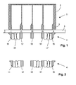
- FIG. 1 shows a schematic longitudinal section through an internal combustion engine 1, a cylinder block 2 with four cylinders and a bearing cover arrangement located below 4 can be seen.
- the five bearing caps 11, 12, 13, 14 and 15 the bearing cap arrangement form together with five bearing blocks 3 on the cylinder block 2 five main bearings I, II, III, IV and V for a crankshaft 5.
- the whole the main bearing I-V is called a crankshaft bearing.
- crankshafts are typically made of steel respectively Made of spheroidal graphite cast iron.
- the bearing caps 11-15 are preferred of a similar or the same material as the crankshaft manufactured, e.g. made of spheroidal graphite (ADI) heat-treated cast iron.
- ADI spheroidal graphite
- the bearing cap assembly 4 in mutually unconnected Subdivide groups of bearing caps connected within the group. to be subdivided from bearing caps connected within the group.
- 1 shows an embodiment of the bearing cap arrangement 4 with three Groups of bearing caps, the first two bearing caps 11 and 12 over a bearing bracket 16 and the last two bearing caps 14 and 15 via one Bearing supports 17 are connected to one another, while the middle bearing cover 13 is arranged separately.
- the middle bearing cover 13 can, for example, via bolt cross connections be connected to the jacket of the cylinder block 2.
- the middle bearing cover 13 also separately on one end face of the cylinder block 2 be attached.
- Figure 2 shows an alternative bearing cap arrangement 4 ', in which the bearing cap are divided into just two unrelated groups. specially the first two bearing caps 11 and 12 are connected to each other and the remaining three bearing caps 13, 14 and 15. To prevent interference from a thermal This group will minimize longitudinal expansion of triplets 13, 14 and 15 preferably (only) on the middle bearing cover 14 by dowels respectively Dowel pins connected to the cylinder block.
Landscapes
- Engineering & Computer Science (AREA)
- General Engineering & Computer Science (AREA)
- Mechanical Engineering (AREA)
- Chemical & Material Sciences (AREA)
- Combustion & Propulsion (AREA)
- Cylinder Crankcases Of Internal Combustion Engines (AREA)
- Shafts, Cranks, Connecting Bars, And Related Bearings (AREA)
Abstract
Description
- Fig. 1
- schematisch einen Längsschnitt durch eine Brennkraftmaschine mit einem Zylinderblock und einer ersten Ausgestaltungsform einer erfindungsgemäßen Lagerdeckel-Anordnung und
- Fig. 2
- eine zweite Ausgestaltungsform einer erfindungsgemäßen Lagerdeckel-Anordnung.
Claims (10)
- Lagerdeckel-Anordnung (4, 4') für ein Kurbelwellenlager, enthaltend eine Anzahl von am Zylinderblock (2) einer Brennkraftmaschine befestigbaren Lagerdeckeln (11-15) zur Lagerung einer Kurbelwelle (5),
dadurch gekennzeichnet, daß
die Lagerdeckel (11-15) teilweise untereinander verbunden sind. - Lagerdeckel-Anordnung nach Anspruch 1,
dadurch gekennzeichnet, daß
diese aus Gußeisen mit Kugelgraphit besteht. - Lagerdeckel-Anordnung nach einem der Ansprüche 1 oder 2,
dadurch gekennzeichnet, daß
diese fünf Lagerdeckel (11-15) enthält, von denen nur der erste (11) und der zweite (12) sowie der vierte (14) und der fünfte (15) miteinander verbunden sind. - Lagerdeckel-Anordnung nach Anspruch 3,
dadurch gekennzeichnet, daß
der mittlere Lagerdeckel (13) am Zylindermantel und/oder an der Stirnseite eines Zylinderblockes (2) befestigbar ist. - Lagerdeckel-Anordnung nach Anspruch 1 oder 2,
dadurch gekennzeichnet, daß
diese fünf Lagerdeckel (11-15) enthält, von denen nur der erste (11) und der zweite (12) sowie der dritte (13), vierte (14) und fünfte (15) miteinander verbunden sind. - Lagerdeckel-Anordnung nach Anspruch 5,
dadurch gekennzeichnet, daß
die Gruppe bestehend aus dem dritten, vierten und fünften Lagerdeckel (11, 12, 13) im Bereich des vierten Lagerdeckels (14) an einem Zylinderblock (2) befestigbar ist. - Kurbelwellenlager für eine Brennkraftmaschine,
dadurch gekennzeichnet, daß
dieses eine Lagerdeckel-Anordnung (4, 4') nach mindestens einem der Ansprüche 1 bis 6 enthält. - Brennkraftmaschine mit einem Zylinderblock (2) und einer Kurbelwelle (5), gekennzeichnet durch ein Kurbelwellenlager nach Anspruch 7.
- Brennkraftmaschine nach Anspruch 8,
dadurch gekennzeichnet, daß
der Zylinderblock (2) aus Aluminium oder einer Aluminium-Legierung besteht. - Brennkraftmaschine nach Anspruch 8 oder 9,
dadurch gekennzeichnet, daß
die Kurbelwelle (5) aus Stahl oder Gußeisen mit Kugelgraphit besteht.
Priority Applications (2)
| Application Number | Priority Date | Filing Date | Title |
|---|---|---|---|
| EP20030101341 EP1477660B1 (de) | 2003-05-14 | 2003-05-14 | Lagerdeckelanordnung für ein Kurbelwellenlager |
| DE50305483T DE50305483D1 (de) | 2003-05-14 | 2003-05-14 | Lagerdeckelanordnung für ein Kurbelwellenlager |
Applications Claiming Priority (1)
| Application Number | Priority Date | Filing Date | Title |
|---|---|---|---|
| EP20030101341 EP1477660B1 (de) | 2003-05-14 | 2003-05-14 | Lagerdeckelanordnung für ein Kurbelwellenlager |
Publications (2)
| Publication Number | Publication Date |
|---|---|
| EP1477660A1 true EP1477660A1 (de) | 2004-11-17 |
| EP1477660B1 EP1477660B1 (de) | 2006-10-25 |
Family
ID=33016994
Family Applications (1)
| Application Number | Title | Priority Date | Filing Date |
|---|---|---|---|
| EP20030101341 Expired - Lifetime EP1477660B1 (de) | 2003-05-14 | 2003-05-14 | Lagerdeckelanordnung für ein Kurbelwellenlager |
Country Status (2)
| Country | Link |
|---|---|
| EP (1) | EP1477660B1 (de) |
| DE (1) | DE50305483D1 (de) |
Cited By (1)
| Publication number | Priority date | Publication date | Assignee | Title |
|---|---|---|---|---|
| DE102010010991A1 (de) * | 2010-03-10 | 2011-09-15 | Eisenwerk Brühl GmbH | Motorblock |
Citations (4)
| Publication number | Priority date | Publication date | Assignee | Title |
|---|---|---|---|---|
| US4520770A (en) | 1981-10-07 | 1985-06-04 | Nissan Motor Co., Ltd. | Automotive internal combustion engine with bearing beam structure |
| JPS60219436A (ja) * | 1984-04-13 | 1985-11-02 | Toyota Motor Corp | エンジンブロツク |
| DE3837834C1 (en) * | 1988-11-08 | 1989-06-01 | Daimler-Benz Aktiengesellschaft, 7000 Stuttgart, De | Crankshaft bearing for an internal combustion engine |
| JP2002339801A (ja) * | 2001-05-17 | 2002-11-27 | Honda Motor Co Ltd | ベアリングキャップ構造 |
-
2003
- 2003-05-14 DE DE50305483T patent/DE50305483D1/de not_active Expired - Lifetime
- 2003-05-14 EP EP20030101341 patent/EP1477660B1/de not_active Expired - Lifetime
Patent Citations (4)
| Publication number | Priority date | Publication date | Assignee | Title |
|---|---|---|---|---|
| US4520770A (en) | 1981-10-07 | 1985-06-04 | Nissan Motor Co., Ltd. | Automotive internal combustion engine with bearing beam structure |
| JPS60219436A (ja) * | 1984-04-13 | 1985-11-02 | Toyota Motor Corp | エンジンブロツク |
| DE3837834C1 (en) * | 1988-11-08 | 1989-06-01 | Daimler-Benz Aktiengesellschaft, 7000 Stuttgart, De | Crankshaft bearing for an internal combustion engine |
| JP2002339801A (ja) * | 2001-05-17 | 2002-11-27 | Honda Motor Co Ltd | ベアリングキャップ構造 |
Non-Patent Citations (2)
| Title |
|---|
| PATENT ABSTRACTS OF JAPAN vol. 010, no. 077 (M - 464) 26 March 1986 (1986-03-26) * |
| PATENT ABSTRACTS OF JAPAN vol. 2003, no. 03 5 May 2003 (2003-05-05) * |
Cited By (1)
| Publication number | Priority date | Publication date | Assignee | Title |
|---|---|---|---|---|
| DE102010010991A1 (de) * | 2010-03-10 | 2011-09-15 | Eisenwerk Brühl GmbH | Motorblock |
Also Published As
| Publication number | Publication date |
|---|---|
| EP1477660B1 (de) | 2006-10-25 |
| DE50305483D1 (de) | 2006-12-07 |
Similar Documents
| Publication | Publication Date | Title |
|---|---|---|
| DE3426208C1 (de) | Kurbelwellenlager fuer Brennkraftmaschinen | |
| DE69713987T2 (de) | Anordnung von Kohlenstoffbremsscheiben für eine Bremseinheit für Luftfahrzeuge sowie Verfahren zur Montage von Scheiben gemäss einer solchen Anordnung | |
| DE1116481B (de) | Anordnung zur Verbindung von zwei mit Praezisionspassung ineinandergesteckten Bauteilen aus Werkstoffen, die unterschiedliche Ausdehnungskoeffizienten aufweisen | |
| DE19537191A1 (de) | Kurbelwellenlagerung für eine Brennkraftmaschine | |
| DE29609950U1 (de) | Motorblock für eine Mehrzylinder-Brennkraftmaschine | |
| DE10250733A1 (de) | Getriebe mit einer Lagereinheit | |
| DE8713285U1 (de) | Antriebswelle mit gruppenweise darauf befestigten Antriebselementen. | |
| DE1750595B2 (de) | Lagerung der kurbelwelle eines v- motors | |
| DE3831002A1 (de) | Verbindung der kurbelwelle einer schalldicht gekapselten brennkraftmaschine mit der koaxialen antriebswelle der ausserhalb der kapsel angeordneten hilfseinrichtungen | |
| DE602005000963T2 (de) | Hydraulischer Motor | |
| EP1477660B1 (de) | Lagerdeckelanordnung für ein Kurbelwellenlager | |
| DE102016005644A1 (de) | Lagereinrichtung zum axialen Lagern einer Kurbelwelle einer Hubkolbenmaschine | |
| DE102011087535A1 (de) | Ausgleichswelle | |
| DE69108635T2 (de) | V-Motor. | |
| DE2904387C2 (de) | Baureihe von mehrzylindrigen Hubkolbenmotoren | |
| EP1024276B1 (de) | Hubkolben-Brennkraftmaschine | |
| DE102017220193A1 (de) | Hubkolben-Brennkraftmaschine mit einem Ausgleich für freie Massenkräfte und -momente | |
| DE3225975C1 (de) | Zusammengesetzte Kurbelwelle | |
| DE102008031993B4 (de) | Split-Pin-Kurbelwelle und Verfahren zur Auslegung einer Familie von V-Motoren | |
| DE2613607A1 (de) | Mehrzylindermotor-auspuffsystem mit zwei separaten auspuffleitungen | |
| DE4331324C2 (de) | Kolbenring-System | |
| DE2849257B1 (de) | Verbrennungskraftmaschine | |
| DE102007024504A1 (de) | Lagerung eines Vorderachsgetriebes bei einem Kraftfahrzeug | |
| DE2755739B2 (de) | Kolben für Hubkolben-Verbrennungskraftmascbinen mit einem außen am Grundkörper des Kolbenschaftes angebauten Element | |
| DE3923250A1 (de) | Steuerwelle |
Legal Events
| Date | Code | Title | Description |
|---|---|---|---|
| PUAI | Public reference made under article 153(3) epc to a published international application that has entered the european phase |
Free format text: ORIGINAL CODE: 0009012 |
|
| AK | Designated contracting states |
Kind code of ref document: A1 Designated state(s): AT BE BG CH CY CZ DE DK EE ES FI FR GB GR HU IE IT LI LU MC NL PT RO SE SI SK TR |
|
| AX | Request for extension of the european patent |
Extension state: AL LT LV MK |
|
| 17P | Request for examination filed |
Effective date: 20050517 |
|
| AKX | Designation fees paid |
Designated state(s): DE FR GB |
|
| GRAP | Despatch of communication of intention to grant a patent |
Free format text: ORIGINAL CODE: EPIDOSNIGR1 |
|
| GRAS | Grant fee paid |
Free format text: ORIGINAL CODE: EPIDOSNIGR3 |
|
| GRAA | (expected) grant |
Free format text: ORIGINAL CODE: 0009210 |
|
| AK | Designated contracting states |
Kind code of ref document: B1 Designated state(s): DE FR GB |
|
| REG | Reference to a national code |
Ref country code: GB Ref legal event code: FG4D Free format text: NOT ENGLISH |
|
| REF | Corresponds to: |
Ref document number: 50305483 Country of ref document: DE Date of ref document: 20061207 Kind code of ref document: P |
|
| GBT | Gb: translation of ep patent filed (gb section 77(6)(a)/1977) |
Effective date: 20070131 |
|
| ET | Fr: translation filed | ||
| PLBE | No opposition filed within time limit |
Free format text: ORIGINAL CODE: 0009261 |
|
| STAA | Information on the status of an ep patent application or granted ep patent |
Free format text: STATUS: NO OPPOSITION FILED WITHIN TIME LIMIT |
|
| 26N | No opposition filed |
Effective date: 20070726 |
|
| REG | Reference to a national code |
Ref country code: FR Ref legal event code: PLFP Year of fee payment: 13 |
|
| PGFP | Annual fee paid to national office [announced via postgrant information from national office to epo] |
Ref country code: DE Payment date: 20150601 Year of fee payment: 13 Ref country code: GB Payment date: 20150424 Year of fee payment: 13 |
|
| PGFP | Annual fee paid to national office [announced via postgrant information from national office to epo] |
Ref country code: FR Payment date: 20150424 Year of fee payment: 13 |
|
| REG | Reference to a national code |
Ref country code: DE Ref legal event code: R119 Ref document number: 50305483 Country of ref document: DE |
|
| GBPC | Gb: european patent ceased through non-payment of renewal fee |
Effective date: 20160514 |
|
| REG | Reference to a national code |
Ref country code: FR Ref legal event code: ST Effective date: 20170131 |
|
| PG25 | Lapsed in a contracting state [announced via postgrant information from national office to epo] |
Ref country code: DE Free format text: LAPSE BECAUSE OF NON-PAYMENT OF DUE FEES Effective date: 20161201 Ref country code: FR Free format text: LAPSE BECAUSE OF NON-PAYMENT OF DUE FEES Effective date: 20160531 |
|
| PG25 | Lapsed in a contracting state [announced via postgrant information from national office to epo] |
Ref country code: GB Free format text: LAPSE BECAUSE OF NON-PAYMENT OF DUE FEES Effective date: 20160514 |