EP1477362A1 - Freizeitfahrzeug - Google Patents
Freizeitfahrzeug Download PDFInfo
- Publication number
- EP1477362A1 EP1477362A1 EP03447109A EP03447109A EP1477362A1 EP 1477362 A1 EP1477362 A1 EP 1477362A1 EP 03447109 A EP03447109 A EP 03447109A EP 03447109 A EP03447109 A EP 03447109A EP 1477362 A1 EP1477362 A1 EP 1477362A1
- Authority
- EP
- European Patent Office
- Prior art keywords
- profile
- clamp
- base profile
- base
- channel
- Prior art date
- Legal status (The legal status is an assumption and is not a legal conclusion. Google has not performed a legal analysis and makes no representation as to the accuracy of the status listed.)
- Withdrawn
Links
- 239000004033 plastic Substances 0.000 claims abstract description 46
- 230000000295 complement effect Effects 0.000 claims 1
- 230000015572 biosynthetic process Effects 0.000 abstract description 7
- 239000004411 aluminium Substances 0.000 description 7
- 229910052782 aluminium Inorganic materials 0.000 description 7
- XAGFODPZIPBFFR-UHFFFAOYSA-N aluminium Chemical compound [Al] XAGFODPZIPBFFR-UHFFFAOYSA-N 0.000 description 7
- 230000008901 benefit Effects 0.000 description 5
- 239000000463 material Substances 0.000 description 4
- 229910052751 metal Inorganic materials 0.000 description 4
- 239000002184 metal Substances 0.000 description 4
- 239000002991 molded plastic Substances 0.000 description 4
- 229920000728 polyester Polymers 0.000 description 4
- 229920002994 synthetic fiber Polymers 0.000 description 3
- 230000000149 penetrating effect Effects 0.000 description 2
- 238000010079 rubber tapping Methods 0.000 description 2
- 238000007789 sealing Methods 0.000 description 2
- 230000007704 transition Effects 0.000 description 2
- 239000000853 adhesive Substances 0.000 description 1
- 230000001070 adhesive effect Effects 0.000 description 1
- 239000002390 adhesive tape Substances 0.000 description 1
- 238000005452 bending Methods 0.000 description 1
- 230000009969 flowable effect Effects 0.000 description 1
- 239000006261 foam material Substances 0.000 description 1
- 230000004048 modification Effects 0.000 description 1
- 238000012986 modification Methods 0.000 description 1
- 239000011120 plywood Substances 0.000 description 1
- 230000002265 prevention Effects 0.000 description 1
- 230000008439 repair process Effects 0.000 description 1
- 239000000565 sealant Substances 0.000 description 1
- 230000003313 weakening effect Effects 0.000 description 1
Images


Classifications
-
- B—PERFORMING OPERATIONS; TRANSPORTING
- B60—VEHICLES IN GENERAL
- B60P—VEHICLES ADAPTED FOR LOAD TRANSPORTATION OR TO TRANSPORT, TO CARRY, OR TO COMPRISE SPECIAL LOADS OR OBJECTS
- B60P3/00—Vehicles adapted to transport, to carry or to comprise special loads or objects
- B60P3/32—Vehicles adapted to transport, to carry or to comprise special loads or objects comprising living accommodation for people, e.g. caravans, camping, or like vehicles
- B60P3/36—Auxiliary arrangements; Arrangements of living accommodation; Details
-
- B—PERFORMING OPERATIONS; TRANSPORTING
- B62—LAND VEHICLES FOR TRAVELLING OTHERWISE THAN ON RAILS
- B62D—MOTOR VEHICLES; TRAILERS
- B62D27/00—Connections between superstructure or understructure sub-units
- B62D27/02—Connections between superstructure or understructure sub-units rigid
-
- B—PERFORMING OPERATIONS; TRANSPORTING
- B62—LAND VEHICLES FOR TRAVELLING OTHERWISE THAN ON RAILS
- B62D—MOTOR VEHICLES; TRAILERS
- B62D33/00—Superstructures for load-carrying vehicles
- B62D33/04—Enclosed load compartments ; Frameworks for movable panels, tarpaulins or side curtains
-
- B—PERFORMING OPERATIONS; TRANSPORTING
- B62—LAND VEHICLES FOR TRAVELLING OTHERWISE THAN ON RAILS
- B62D—MOTOR VEHICLES; TRAILERS
- B62D33/00—Superstructures for load-carrying vehicles
- B62D33/04—Enclosed load compartments ; Frameworks for movable panels, tarpaulins or side curtains
- B62D33/046—Enclosed load compartments ; Frameworks for movable panels, tarpaulins or side curtains built up with flat self-supporting panels; Fixed connections between panels
Definitions
- the present invention relates to a recreational vehicle, such as a caravan, a mobile home or a motor caravan, comprising a living room and a kitchen and having two side walls and a front, a back and a roof fixed to the side walls, the side walls showing a contour which comprises at least one curved portion in the area where the front, the back and the roof are fixed to the side walls, and the front, the back and/or the roof comprising at least one plastic plate which extends between the side walls and which has two side edges, at least one of which is secured to one of said side walls by being clamped underneath a clamp profile secured to said side wall along at least a portion of the contour thereof which comprises at least said curved portion, the clamp profile being bent along said curved portion and a resilient seal being provided between the clamp profile and the side edge of the plastic plate.
- a recreational vehicle such as a caravan, a mobile home or a motor caravan, comprising a living room and a kitchen and having two side walls and a front, a back and a roof fixed to
- the clamp profiles of a caravan extend over the entire area of the contour of the side walls where the front, the roof and the back are fixed to the side walls.
- the clamp profiles are generally L-shaped and have one leg applied onto the side edge of the plates which form the front, the roof and the back and the other leg onto the outer surface of the side wall. In this way, an aesthetic covering of the transition of the edge between the side walls and the front, the roof and the back is achieved.
- a resilient seal is applied between the clamp profiles and the side edges of the plates forming the front, the roof and the back so that a watertight seal is obtained.
- self tapping screws which are screwed through the clamp profiles and the side edges of the plates forming the front, the roof and the back into the edge surfaces of the side walls.
- a clamp profile which enables to fix certain applications, for example a plastic bottle box, to the outside of a caravan.
- these side edges are no longer clamped underneath the clamp profiles but these clamp profiles are provided on top with a rail showing an upwardly directed channel wherein the edge of the application is inserted.
- the channel is provided with an undercut and the outer wall of the channel is deformed to close the opening and to fit against the application.
- a drawback of such a mounting system is that the application cannot be fixed very securely.
- the required watertight seal cannot be achieved between the rail and the application so that a watertight wall has still to be provided underneath or behind the application.
- a further drawback is that only applications having an edge curved over an angle can be fixed into the rail.
- a flat plastic plate for example a roof plate, or an application showing an edge which is locally flat into the rail. Consequently, it is very difficult to achieve a watertight transition between the application having curved edges and the adjacent flat plates. Again, this means that a watertight flat wall has to be provided underneath or behind the application.
- An object of the present invention is now to provide a new recreational vehicle wherein at least one of the side edges of the plastic plate forming a portion of the front, the roof and/or the back is rigidly fixed to the side wall by being clamped underneath a clamp profile and wherein a watertight seal is still obtained between the plastic plate and the clamp profile but wherein the problem of the tear formation in the plastic plate is avoided at least to a considerable extend.
- the vehicle according to the invention is characterised in that said clamp profile is part of an assembly for mounting the plastic plate to said side wall, which mounting assembly further comprises at least a base profile which is fixed to the side wall along said portion of the contour thereof and which is bent along said curved portion of this contour, the base profile comprising a generally L-shaped portion, a first leg of which extends along an edge surface of the side wall and a second leg of which extends along an outer surface of the side wall, and the mounting assembly comprising means, arranged next to the side edge of the plastic plate, for mounting the clamp profile onto the base profile to clamp the side edge of the plastic plate between the clamp profile and said first leg of the base profile.
- the plastic plate is rigidly fixed to the side wall by being clamped between the clamp and the base profiles and a watertight seal is achieved at the same time by providing a resilient seal between the clamp profile and the side edge of the plastic plate.
- a watertight seal is achieved at the same time by providing a resilient seal between the clamp profile and the side edge of the plastic plate.
- the plastic plates used in the vehicle according to the invention have usually side edges with a thickness comprised between 1 and 5 mm, more particularly between 1 and 3 mm whilst the metal (aluminium) plates which may also be used in addition to the plastic plates have usually a thickness of between 0.5 and 1 mm.
- a mounting assembly comprising a base profile and a clamp profile for mounting a thicker roof panel onto the side walls is already disclosed in DE-A-43 34 269.
- the base and the clamp profiles are however not suitable for a recreational vehicle according to the invention since they cannot be bent around the rounded corners and since the roof panel has further to be glued first to the clamp profile.
- the roof panel has consequently to be a flat panel.
- said clamp profile and said base profile have a height, measured in a direction parallel to the side wall and perpendicular to the contour thereof, which is smaller than 25 mm, and preferably smaller than 20 mm.
- An advantage of this embodiment is that the base and the clamp profiles does not have to be pre-shaped but that they can be bent manually when fixing them to the side wall.
- the invention relates to a recreational vehicle such as a caravan, a mobile home or a motor caravan, comprising a living room and a kitchen.
- the caravan illustrated in Figure 1 comprises a chassis with wheels 1 and a floor mounted thereon, two side walls 2, a front 3, a roof 4 and a back 5.
- the front 3, roof 4 and back 5 are made of plastic plates 6 which have side edges fixed to the side walls 2.
- the front 3 of the caravan consists of a moulded plastic plate 6 having an aerodynamic and aesthetic shape and providing a box 7 for a gas bottle or for other equipment.
- the front is usually made of ABS but could also be made of other synthetic materials like polyester.
- the roof 4 and the back 5 consist on the contrary of a flat plate 6 which may be made of a synthetic material like polyester but which can also be made of a metal like aluminium. Between the front 3 and the roof a strip 8 is arranged which provides for a watertight connection.
- the side walls 2 of the caravan shows a contour which comprises curved portions in the area where the front 3, the roof 4 and the back 5 are fixed to the side walls 2.
- the front, the roof and the back are fixed to the side walls by means of a mounting assembly which extends in one piece in this area around the contour of the side walls.
- the mounting assembly comprises two profiles which are mounted onto one another, namely a base profile 9 and a clamp profile 10 mounted thereon. In the area of the curved portions of the side wall contour, these profiles 9, 10 are bent to follow the contour of the side wall 2.
- the contour of the side walls shows curved portions having a curvature radius which is smaller than 100 cm and in particular smaller than 50 mm so that a substantial bending of the profiles is required.
- the curvature radius of the curved portions of the side wall contour are however usually larger than 15 cm, and in particular larger than 20 cm, when use is made of profiles which are bent around the contour of the side wall.
- the profiles 8, 9 have preferably a height h 1 , h 2 , measured in a direction parallel to the side wall 2 and perpendicular to the contour thereof, which is smaller than 25 mm and preferably smaller than 20 mm.
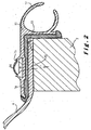
- FIG. 2 a prior art assembly for mounting the plates 6 of the front 3, the roof 4 and the back 5 of the caravan onto the side walls 2 is illustrated.
- This prior art mounting assembly consists of a clamp profile 11 which is fixed by means of self tapping screws 12 to an edge surface 13 of the side wall 2.
- the side edges of the front, roof and back plates are arranged between the clamp profile 11 and the edge surface 13 and are penetrated by the screws 12.
- a resilient seal 14 in particular a rubber seal, is provided to achieve a watertight seal.
- the clamp profile 11 shows a groove 15 for the heads of the screws, which groove 15 is closed by means of a finishing strip 16.
- the clamp profile 11 ensures a reliable fixation of the front, roof and back plates, and provides for a watertight sealing and for an aesthetic finishing of the contour of the side wall 2.
- the clamp profile 11 may also comprise a rail 17 for attaching a tent.
- a major drawback is that when plastic plates 6 are used for the front, the roof and/or the back, tears are produced very often in these plates 6 due to the difference in thermal expansion coefficient between the plastic plates and the metal (extruded aluminium) of the profile 11 and the material of the side wall 2 (usually a wooden frame filled with an insulating foam material and covered with a sheet material such as plywood on the inside and aluminium or polyester on the outside).
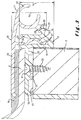
- FIG. 3 A first embodiment of this mounting assembly is illustrated in Figure 3.
- a same plastic plate 6 as illustrated in Figure 2 namely a moulded plastic plate 6 having a convex surface and substantially flat side edges, is clamped in the same way as in Figure 2 underneath the clamp profile 10, including a resilient seal 14 between the clamp profile 10 and the side edge of the plate 6, so that the same advantages are achieved.
- edges of the plastic plate 6 are now clamped between the clamp profile 10 and a base profile 9 and that the clamp profile 10 is no longer fixed by means of screws penetrating the plastic plate 6 but it is mounted onto the base profile 9 by means of mounting means which are arranged next to the side edge of the plastic plate 6.
- the base profile 9 of the mounting assembly illustrated in Figure 3 comprises a generally L-shaped portion having a first leg 18 and a second leg 19.
- the first leg 18 of the base profile 9 is fixed by means of screws 20 to the edge surface 13 of the side wall 2, more particularly in such a manner that the second leg 19 engages the outer surface of the side wall 2.
- a groove 21 is provided in the upper side of the first leg 18 for receiving the heads of the screws 20 and, on the lower side, ridges 22 to compensate for the depth of the groove 21.
- the base profile 9 could also be glued or adhered to the side wall 2.
- the base profile 9 For being able to mount the clamp profile 10 onto the base profile 9, the base profile 9 comprises a channel 23 which has its open end directed towards the clamp profile 10 and this clamp profile 10 comprises a flange 24 arranged to be clamped into the channel 23.
- the flange 24 comprises a C-shaped portion 25 which is compressed to clamp the flange in the channel 23.
- the flange 24 extends downward from a base portion 26 of the clamp profile so that, when pushing the flange 24 in the channel 23, the side edge of the plate 6 and the seal 14 applied thereon are clamped between this base portion 26 and the upper surface of the first leg 18 of the base profile 9.
- the inner surface of the channel 23 is provided with a number of grooves 27. Since the channel 23 extends on the outer side of the second leg 19 of the base profile 9, the side edge of the plate 6 has not to be penetrated by any fixing means.
- the channel 23 extends at least partially along or in other words next to the second leg 19 of the base profile 9, in a direction perpendicular to the outer surface of the side wall 2, the second leg 19 forming more particularly a portion of a side wall of the channel 23.
- An important advantage of this embodiment is that the height h 1 of the base profile can be kept relatively small so that the base profile can be bent by hand according to the outer contour of the side wall 2.
- the base portion 26 of the clamp profile 10 is provided with a further flange 28 which extends along the outer side of the channel 23 of the base profile 9 and which is urged laterally against this base profile 9 when the plate 6 is clamped between the clamp profile and the base profile so that the base portion of the clamp profile 10 tends to rotate somewhat around the flange 24.
- the further flange 28 and/or the base profile 9 are provided with means for prevention a sliding of the further flange 28 with respect to the base profile.
- these means comprise ridges 29 forming grooves 30 in the further flange 28 and one larger ridge 31 to the base profile 9, having a rounded head which penetrates into the grooves 30.
- the ridges and grooves prevent a sliding of the further flange 28 of the clamp profile 10 with respect to the base profile 9 under the normal conditions of use but still enable a mutual sliding of these elements when the clamp profile is mounted on or removed from the base profile (to enable repair).
- the further flange 28 is part of a rail 32 arranged to attach a tent to the caravan.
- a rail is however usually only provided on one side of the caravan so that the clamp profile used on the other side does not have to show such a rail.
- An important advantage of the mounting assembly illustrated in Figure 3 is that, due to the presence of ridges/grooves in the channel 23 and on the further flange 28, the clamp profile can be fixed on different distances from the base profile. In this way, the mounting assembly is suited for clamping plates of different thicknesses, for example thicker plastic plates and thinner aluminium plates.
- Figure 4 illustrates an alternative embodiment of the mounting assembly which also allows to clamp plates of different thicknesses.
- a resilient seal 37 is additionally provided between the second leg 19 of the base profile 9 and the outer surface of the side wall 2.
- the main difference between the previous embodiment is further that the flange 24 which extends in the channel 23 of the base profile 9, is replaced by a thicker flange 24 showing a channel 33 having a ridged inner surface and an open end directed towards the bottom of the channel 23 in the base profile 9.
- the flange 24 is now fixed into this channel by means of screws 34 which are screwed through the bottom of the channel 23 into the channel 33 in the flange 24.
- the heads of the screws 34 are situated in a groove 35 which is closed of by means of a finishing strip 36. Due to the fact that the flange 24 of the clamping profile 10 can be made thicker in the present embodiment, the further flange 28 can be omitted.
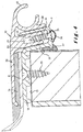
- Figure 5 illustrates a further alternative embodiment of the mounting assembly illustrated in Figure 3.
- a resilient seal 37 is also additionally provided between the second leg 19 of the base profile 9 and the outer surface of the side wall 2.
- the flange 24 projecting from the base portion of the clamp profile 10 has two ridged outer surfaces, the ridges forming is cross-sectional view saw teeth, having one oblique edge and one perpendicular edge.
- the outer surface of the base profile is also ridged whilst the further flange 28, more particularly the tent rail 32, is provided with a ridge 38 arranged to penetrate in the grooves formed by the ridged outer surface of the base profile.
- a special feature is further that the base portion of the clamp profile 10 is somewhat buckled above the side edge of the plate 6, and shows a weakening groove 39, so that the curved free extremity of the clamp profile 10 can be clamped with a greater force against the resilient seal 14.
- Figure 6 illustrates an alternative embodiment of the mounting assembly wherein the base profile 9 is not provided with a channel 23 for receiving a flange 24 of the clamp profile 10. Instead, the second leg 19 of the base profile 9 is provided with a outwardly projecting flange 40. This flange 40 is provided with holes for screws 41 which can be screwed in a channel 42 formed by the clamp profile 10 and having its open end directed towards the base profile 9, more particularly towards the projecting flange 40 thereof.
- the inside wall of the channel 42 is provided with an inwardly projecting flange 43 which engages the base profile 9, more particularly the second leg 19 thereof, whilst the channel 42 and the longitudinal axes of the screws 41 form an angle with the outer surface of the side wall 2 so that the clamp profile 10 is prevented from rotating (in the clockwise direction as seen in Figure 6) when the plate 6 is clamped underneath the clamp profile 10.
- a groove is provided in the projecting flange 40 of the base profile 9, which groove is closed off by means of a finishing strip 44.
- a resilient seal similar to the seal illustrated in Figure 2, between the base profile 9 and the edge surface 13 of the side wall 2.
- a double-sided adhesive tape can further be applied onto the first leg 18 of the base profile 9 so that the plate 6 adheres thereto when the clamp profile is applied.
- a sealant/adhesive material (which preferably remains somewhat flowable) can first be applied onto the side edge of the plate 6 before applying the resilient seal thereto.
Priority Applications (1)
| Application Number | Priority Date | Filing Date | Title |
|---|---|---|---|
| EP03447109A EP1477362A1 (de) | 2003-05-14 | 2003-05-14 | Freizeitfahrzeug |
Applications Claiming Priority (1)
| Application Number | Priority Date | Filing Date | Title |
|---|---|---|---|
| EP03447109A EP1477362A1 (de) | 2003-05-14 | 2003-05-14 | Freizeitfahrzeug |
Publications (1)
| Publication Number | Publication Date |
|---|---|
| EP1477362A1 true EP1477362A1 (de) | 2004-11-17 |
Family
ID=33017056
Family Applications (1)
| Application Number | Title | Priority Date | Filing Date |
|---|---|---|---|
| EP03447109A Withdrawn EP1477362A1 (de) | 2003-05-14 | 2003-05-14 | Freizeitfahrzeug |
Country Status (1)
| Country | Link |
|---|---|
| EP (1) | EP1477362A1 (de) |
Cited By (4)
| Publication number | Priority date | Publication date | Assignee | Title |
|---|---|---|---|---|
| EP1609928A1 (de) * | 2004-06-22 | 2005-12-28 | Chateau Caravans | Freizeitfahrzeug |
| WO2007143771A1 (de) * | 2006-06-14 | 2007-12-21 | Rainer Karl Schuh | Lkw-aufsatz |
| EP2143623A1 (de) * | 2008-07-12 | 2010-01-13 | AluTeam Fahrzeugtechnik GmbH | Verbindung, insbesondere für Teile von Fahrzeugaufbauten |
| WO2014079652A1 (de) * | 2012-11-26 | 2014-05-30 | Siemens Aktiengesellschaft | Wagenkastenteil |
Citations (6)
| Publication number | Priority date | Publication date | Assignee | Title |
|---|---|---|---|---|
| FR2602554A1 (fr) * | 1986-08-08 | 1988-02-12 | Trigano | Systeme d'assemblage de panneaux de caravanes, vehicules ou autres structures legeres habitables |
| US5048999A (en) * | 1990-04-06 | 1991-09-17 | Dr. Ing. H.C.F. Porsche Aktiengesellschaft | Clamped connection between a profile part and a sheet metal part by means of a clamping strip |
| DE4334269A1 (de) * | 1992-10-09 | 1994-05-05 | Eurocon Oy Hyrylae | Laderaumkonstruktion für ein Fahrzeug |
| FR2717868A1 (fr) * | 1994-03-22 | 1995-09-29 | Lamberet Const Isotherme | Dispositif pour l'assemblage des panneaux composites et isolants d'un caisson isotherme. |
| EP0802080A2 (de) * | 1996-04-20 | 1997-10-22 | Tabbert Caravan GmbH | Kantenprofilsystem für Wohnanhänger, Wohnmobile oder dergleichen |
| DE19933619A1 (de) * | 1999-07-17 | 2001-01-25 | Eura Mobil Gmbh | Fahrzeug mit Wohneinrichtung |
-
2003
- 2003-05-14 EP EP03447109A patent/EP1477362A1/de not_active Withdrawn
Patent Citations (6)
| Publication number | Priority date | Publication date | Assignee | Title |
|---|---|---|---|---|
| FR2602554A1 (fr) * | 1986-08-08 | 1988-02-12 | Trigano | Systeme d'assemblage de panneaux de caravanes, vehicules ou autres structures legeres habitables |
| US5048999A (en) * | 1990-04-06 | 1991-09-17 | Dr. Ing. H.C.F. Porsche Aktiengesellschaft | Clamped connection between a profile part and a sheet metal part by means of a clamping strip |
| DE4334269A1 (de) * | 1992-10-09 | 1994-05-05 | Eurocon Oy Hyrylae | Laderaumkonstruktion für ein Fahrzeug |
| FR2717868A1 (fr) * | 1994-03-22 | 1995-09-29 | Lamberet Const Isotherme | Dispositif pour l'assemblage des panneaux composites et isolants d'un caisson isotherme. |
| EP0802080A2 (de) * | 1996-04-20 | 1997-10-22 | Tabbert Caravan GmbH | Kantenprofilsystem für Wohnanhänger, Wohnmobile oder dergleichen |
| DE19933619A1 (de) * | 1999-07-17 | 2001-01-25 | Eura Mobil Gmbh | Fahrzeug mit Wohneinrichtung |
Cited By (6)
| Publication number | Priority date | Publication date | Assignee | Title |
|---|---|---|---|---|
| EP1609928A1 (de) * | 2004-06-22 | 2005-12-28 | Chateau Caravans | Freizeitfahrzeug |
| BE1016083A3 (nl) * | 2004-06-22 | 2006-02-07 | Chateau Caravans N V | Recreatievoertuig. |
| WO2007143771A1 (de) * | 2006-06-14 | 2007-12-21 | Rainer Karl Schuh | Lkw-aufsatz |
| EA017505B1 (ru) * | 2006-06-14 | 2013-01-30 | Райнер Карл Шу | Кузов грузового автомобиля |
| EP2143623A1 (de) * | 2008-07-12 | 2010-01-13 | AluTeam Fahrzeugtechnik GmbH | Verbindung, insbesondere für Teile von Fahrzeugaufbauten |
| WO2014079652A1 (de) * | 2012-11-26 | 2014-05-30 | Siemens Aktiengesellschaft | Wagenkastenteil |
Similar Documents
| Publication | Publication Date | Title |
|---|---|---|
| US7905071B2 (en) | Use of a window glass comprising a profiled bead for installing it in an opening | |
| KR950008989B1 (ko) | 단부에 압착식 프로파일 스트립이 장착된 창유리 | |
| US4259812A (en) | Edge molding for vehicle doors | |
| US5384995A (en) | Spacer for windshield bracket | |
| US7159926B2 (en) | Vehicle trim panel securement | |
| US5056850A (en) | Window reveal molding | |
| US4458459A (en) | Sectional molding for surrounding a pane of glass sealed in the window opening of a vehicle, or the like | |
| US6446392B1 (en) | Window weatherstrip for motor vehicles | |
| US6848218B2 (en) | Window sealing strip for a convertible | |
| US5095669A (en) | Spacer for windshield bracket | |
| US6419134B1 (en) | Device for detachable fastening of a load carrier on a vehicle | |
| US4783116A (en) | Sunroof frame assembly for vehicles | |
| US5619827A (en) | Roof edge flashing and anchoring system | |
| EP1477362A1 (de) | Freizeitfahrzeug | |
| US5112101A (en) | Window reveal molding | |
| JP2001512554A (ja) | プラスチックと金属要素とを接続するための締付け装置 | |
| WO2004044874A1 (en) | Mounting for sheet material | |
| US7334309B2 (en) | Method of mounting a roof assembly into the interior of a vehicle; as well as such roof assembly and a vehicle | |
| US4585269A (en) | Vehicle sun roofs | |
| US9611660B2 (en) | Vehicle corner rail assembly | |
| US20080265627A1 (en) | Securing Device | |
| US20130205673A1 (en) | Bonded-in, anti-vandalism transit vehicle window system | |
| JPH07269087A (ja) | 端部構造 | |
| AU2015101030A4 (en) | Utility vehicle tub canopy attachment assembly | |
| EP1609928B1 (de) | Freizeitfahrzeug |
Legal Events
| Date | Code | Title | Description |
|---|---|---|---|
| PUAI | Public reference made under article 153(3) epc to a published international application that has entered the european phase |
Free format text: ORIGINAL CODE: 0009012 |
|
| AK | Designated contracting states |
Kind code of ref document: A1 Designated state(s): AT BE BG CH CY CZ DE DK EE ES FI FR GB GR HU IE IT LI LU MC NL PT RO SE SI SK TR |
|
| AX | Request for extension of the european patent |
Extension state: AL LT LV MK |
|
| AKX | Designation fees paid | ||
| REG | Reference to a national code |
Ref country code: DE Ref legal event code: 8566 |
|
| STAA | Information on the status of an ep patent application or granted ep patent |
Free format text: STATUS: THE APPLICATION IS DEEMED TO BE WITHDRAWN |
|
| 18D | Application deemed to be withdrawn |
Effective date: 20050518 |