EP1477234A2 - Ensemble pour le conditionnement et la distribution d'un produit, notamment sous forme d'un échantillon - Google Patents
Ensemble pour le conditionnement et la distribution d'un produit, notamment sous forme d'un échantillon Download PDFInfo
- Publication number
- EP1477234A2 EP1477234A2 EP04291007A EP04291007A EP1477234A2 EP 1477234 A2 EP1477234 A2 EP 1477234A2 EP 04291007 A EP04291007 A EP 04291007A EP 04291007 A EP04291007 A EP 04291007A EP 1477234 A2 EP1477234 A2 EP 1477234A2
- Authority
- EP
- European Patent Office
- Prior art keywords
- container
- assembly
- movable member
- lip
- product
- Prior art date
- Legal status (The legal status is an assumption and is not a legal conclusion. Google has not performed a legal analysis and makes no representation as to the accuracy of the status listed.)
- Withdrawn
Links
Images


Classifications
-
- F—MECHANICAL ENGINEERING; LIGHTING; HEATING; WEAPONS; BLASTING
- F16—ENGINEERING ELEMENTS AND UNITS; GENERAL MEASURES FOR PRODUCING AND MAINTAINING EFFECTIVE FUNCTIONING OF MACHINES OR INSTALLATIONS; THERMAL INSULATION IN GENERAL
- F16F—SPRINGS; SHOCK-ABSORBERS; MEANS FOR DAMPING VIBRATION
- F16F1/00—Springs
- F16F1/02—Springs made of steel or other material having low internal friction; Wound, torsion, leaf, cup, ring or the like springs, the material of the spring not being relevant
- F16F1/025—Springs made of steel or other material having low internal friction; Wound, torsion, leaf, cup, ring or the like springs, the material of the spring not being relevant characterised by having a particular shape
- F16F1/028—Springs made of steel or other material having low internal friction; Wound, torsion, leaf, cup, ring or the like springs, the material of the spring not being relevant characterised by having a particular shape cylindrical, with radial openings
-
- B—PERFORMING OPERATIONS; TRANSPORTING
- B05—SPRAYING OR ATOMISING IN GENERAL; APPLYING FLUENT MATERIALS TO SURFACES, IN GENERAL
- B05B—SPRAYING APPARATUS; ATOMISING APPARATUS; NOZZLES
- B05B11/00—Single-unit hand-held apparatus in which flow of contents is produced by the muscular force of the operator at the moment of use
- B05B11/0005—Components or details
- B05B11/0037—Containers
- B05B11/0039—Containers associated with means for compensating the pressure difference between the ambient pressure and the pressure inside the container, e.g. pressure relief means
- B05B11/0044—Containers associated with means for compensating the pressure difference between the ambient pressure and the pressure inside the container, e.g. pressure relief means compensating underpressure by ingress of atmospheric air into the container, i.e. with venting means
-
- B—PERFORMING OPERATIONS; TRANSPORTING
- B05—SPRAYING OR ATOMISING IN GENERAL; APPLYING FLUENT MATERIALS TO SURFACES, IN GENERAL
- B05B—SPRAYING APPARATUS; ATOMISING APPARATUS; NOZZLES
- B05B11/00—Single-unit hand-held apparatus in which flow of contents is produced by the muscular force of the operator at the moment of use
- B05B11/0005—Components or details
- B05B11/0062—Outlet valves actuated by the pressure of the fluid to be sprayed
-
- B—PERFORMING OPERATIONS; TRANSPORTING
- B05—SPRAYING OR ATOMISING IN GENERAL; APPLYING FLUENT MATERIALS TO SURFACES, IN GENERAL
- B05B—SPRAYING APPARATUS; ATOMISING APPARATUS; NOZZLES
- B05B11/00—Single-unit hand-held apparatus in which flow of contents is produced by the muscular force of the operator at the moment of use
- B05B11/01—Single-unit hand-held apparatus in which flow of contents is produced by the muscular force of the operator at the moment of use characterised by the means producing the flow
- B05B11/10—Pump arrangements for transferring the contents from the container to a pump chamber by a sucking effect and forcing the contents out through the dispensing nozzle
- B05B11/1001—Piston pumps
-
- B—PERFORMING OPERATIONS; TRANSPORTING
- B05—SPRAYING OR ATOMISING IN GENERAL; APPLYING FLUENT MATERIALS TO SURFACES, IN GENERAL
- B05B—SPRAYING APPARATUS; ATOMISING APPARATUS; NOZZLES
- B05B11/00—Single-unit hand-held apparatus in which flow of contents is produced by the muscular force of the operator at the moment of use
- B05B11/01—Single-unit hand-held apparatus in which flow of contents is produced by the muscular force of the operator at the moment of use characterised by the means producing the flow
- B05B11/10—Pump arrangements for transferring the contents from the container to a pump chamber by a sucking effect and forcing the contents out through the dispensing nozzle
- B05B11/1038—Pressure accumulation pumps, i.e. pumps comprising a pressure accumulation chamber
- B05B11/1039—Pressure accumulation pumps, i.e. pumps comprising a pressure accumulation chamber the outlet valve being mechanically opened after a defined accumulation stroke
-
- B—PERFORMING OPERATIONS; TRANSPORTING
- B05—SPRAYING OR ATOMISING IN GENERAL; APPLYING FLUENT MATERIALS TO SURFACES, IN GENERAL
- B05B—SPRAYING APPARATUS; ATOMISING APPARATUS; NOZZLES
- B05B11/00—Single-unit hand-held apparatus in which flow of contents is produced by the muscular force of the operator at the moment of use
- B05B11/01—Single-unit hand-held apparatus in which flow of contents is produced by the muscular force of the operator at the moment of use characterised by the means producing the flow
- B05B11/10—Pump arrangements for transferring the contents from the container to a pump chamber by a sucking effect and forcing the contents out through the dispensing nozzle
- B05B11/1042—Components or details
- B05B11/1059—Means for locking a pump or its actuation means in a fixed position
-
- B—PERFORMING OPERATIONS; TRANSPORTING
- B05—SPRAYING OR ATOMISING IN GENERAL; APPLYING FLUENT MATERIALS TO SURFACES, IN GENERAL
- B05B—SPRAYING APPARATUS; ATOMISING APPARATUS; NOZZLES
- B05B11/00—Single-unit hand-held apparatus in which flow of contents is produced by the muscular force of the operator at the moment of use
- B05B11/01—Single-unit hand-held apparatus in which flow of contents is produced by the muscular force of the operator at the moment of use characterised by the means producing the flow
- B05B11/10—Pump arrangements for transferring the contents from the container to a pump chamber by a sucking effect and forcing the contents out through the dispensing nozzle
- B05B11/1042—Components or details
- B05B11/1066—Pump inlet valves
- B05B11/107—Gate valves; Sliding valves
-
- B—PERFORMING OPERATIONS; TRANSPORTING
- B05—SPRAYING OR ATOMISING IN GENERAL; APPLYING FLUENT MATERIALS TO SURFACES, IN GENERAL
- B05B—SPRAYING APPARATUS; ATOMISING APPARATUS; NOZZLES
- B05B11/00—Single-unit hand-held apparatus in which flow of contents is produced by the muscular force of the operator at the moment of use
- B05B11/01—Single-unit hand-held apparatus in which flow of contents is produced by the muscular force of the operator at the moment of use characterised by the means producing the flow
- B05B11/10—Pump arrangements for transferring the contents from the container to a pump chamber by a sucking effect and forcing the contents out through the dispensing nozzle
- B05B11/1042—Components or details
- B05B11/1073—Springs
- B05B11/1074—Springs located outside pump chambers
-
- B—PERFORMING OPERATIONS; TRANSPORTING
- B05—SPRAYING OR ATOMISING IN GENERAL; APPLYING FLUENT MATERIALS TO SURFACES, IN GENERAL
- B05B—SPRAYING APPARATUS; ATOMISING APPARATUS; NOZZLES
- B05B11/00—Single-unit hand-held apparatus in which flow of contents is produced by the muscular force of the operator at the moment of use
- B05B11/01—Single-unit hand-held apparatus in which flow of contents is produced by the muscular force of the operator at the moment of use characterised by the means producing the flow
- B05B11/10—Pump arrangements for transferring the contents from the container to a pump chamber by a sucking effect and forcing the contents out through the dispensing nozzle
- B05B11/1042—Components or details
- B05B11/1073—Springs
- B05B11/1077—Springs characterised by a particular shape or material
-
- B—PERFORMING OPERATIONS; TRANSPORTING
- B05—SPRAYING OR ATOMISING IN GENERAL; APPLYING FLUENT MATERIALS TO SURFACES, IN GENERAL
- B05B—SPRAYING APPARATUS; ATOMISING APPARATUS; NOZZLES
- B05B1/00—Nozzles, spray heads or other outlets, with or without auxiliary devices such as valves, heating means
- B05B1/34—Nozzles, spray heads or other outlets, with or without auxiliary devices such as valves, heating means designed to influence the nature of flow of the liquid or other fluent material, e.g. to produce swirl
- B05B1/3405—Nozzles, spray heads or other outlets, with or without auxiliary devices such as valves, heating means designed to influence the nature of flow of the liquid or other fluent material, e.g. to produce swirl to produce swirl
- B05B1/341—Nozzles, spray heads or other outlets, with or without auxiliary devices such as valves, heating means designed to influence the nature of flow of the liquid or other fluent material, e.g. to produce swirl to produce swirl before discharging the liquid or other fluent material, e.g. in a swirl chamber upstream the spray outlet
- B05B1/3421—Nozzles, spray heads or other outlets, with or without auxiliary devices such as valves, heating means designed to influence the nature of flow of the liquid or other fluent material, e.g. to produce swirl to produce swirl before discharging the liquid or other fluent material, e.g. in a swirl chamber upstream the spray outlet with channels emerging substantially tangentially in the swirl chamber
- B05B1/3431—Nozzles, spray heads or other outlets, with or without auxiliary devices such as valves, heating means designed to influence the nature of flow of the liquid or other fluent material, e.g. to produce swirl to produce swirl before discharging the liquid or other fluent material, e.g. in a swirl chamber upstream the spray outlet with channels emerging substantially tangentially in the swirl chamber the channels being formed at the interface of cooperating elements, e.g. by means of grooves
- B05B1/3436—Nozzles, spray heads or other outlets, with or without auxiliary devices such as valves, heating means designed to influence the nature of flow of the liquid or other fluent material, e.g. to produce swirl to produce swirl before discharging the liquid or other fluent material, e.g. in a swirl chamber upstream the spray outlet with channels emerging substantially tangentially in the swirl chamber the channels being formed at the interface of cooperating elements, e.g. by means of grooves the interface being a plane perpendicular to the outlet axis
-
- B—PERFORMING OPERATIONS; TRANSPORTING
- B05—SPRAYING OR ATOMISING IN GENERAL; APPLYING FLUENT MATERIALS TO SURFACES, IN GENERAL
- B05B—SPRAYING APPARATUS; ATOMISING APPARATUS; NOZZLES
- B05B11/00—Single-unit hand-held apparatus in which flow of contents is produced by the muscular force of the operator at the moment of use
- B05B11/01—Single-unit hand-held apparatus in which flow of contents is produced by the muscular force of the operator at the moment of use characterised by the means producing the flow
- B05B11/10—Pump arrangements for transferring the contents from the container to a pump chamber by a sucking effect and forcing the contents out through the dispensing nozzle
- B05B11/1042—Components or details
- B05B11/1043—Sealing or attachment arrangements between pump and container
Definitions
- the present invention relates to a device for packaging and distribution under pressure, in particular in spray form, of a fluid product. More particularly, the invention preferably relates to a sprayer miniature, preferably disposable, suitable for packaging in the form of a sample of cosmetic products, in particular perfumes.
- the product is preferably liquid.
- the miniature pump like any pump fitted to containers larger dimensions, includes a pump body inside which moves a movable piston between a first position in which the body of pump is of maximum volume and a second position in which the volume of the pump body is minimal.
- the pump body is in selective communication with the container via a dip tube and an intake valve, especially under shape of a ball.
- valve admission is closed.
- an outlet valve located upstream of the orifice dispenser, is opened under product pressure.
- the product is distributed under pulverized form.
- the piston When the user releases the pressure exerted on the organ actuation, the piston, under the effect of a spring, rises in the first position by creating a vacuum inside the pump body.
- the inlet valve is opened under the effect of the vacuum prevailing inside the pump body, and the outlet valve is closed.
- a volume of air corresponding to the volume of product transferred from the container to the pump body, enters the container via an appropriate vent hole.
- This miniature container system also equipped with a pump miniature, although satisfactory from the point of view of the simplicity of use for the consumer, and from the point of view of the quality of the spray obtained, suffers from major drawback related to its cost and the complexity of handling and mounting of the small components that compose it.
- Document FR-A-2,393,279 discloses a device for delivering precise and constant doses of liquids.
- the liquid in a tank of such a device descends by gravity into a metering chamber defining the volume of a dose of product expelled each time the push button is pressed equipping this tank.
- the problem with this type of device is that it does not not allow optimal emptying of the tank, especially when the product is viscous or when it tends to include air bubbles. Indeed, such bubbles prevent repeatable doses.
- the liquid is a perfume with oils, so the surface tension of the liquid relatively to the interior walls of the device is high. If a bubble included in the liquid is formed between two parts of the device, in particular at the level an orifice opening into the metering chamber, then such a bubble can prevent the liquid filling of this chamber repeatedly and expected. The dose of liquid delivered is no longer guaranteed.
- the total volume of product to be distributed decreases with each new actuation. But the dose isolated from this total volume of product is, for each actuation, reproducible, until the total volume of product becomes less than the volume of a dose.
- the spraying is identical in nature to each actuation. Indeed, the cooperation of the first lip with the inner wall allows the formation of a temporary chamber in which this dose is pressurized.
- the temporary room is only filled with product, so the air / product ratio does not affect the spraying the product from the temporary chamber.
- this room temporary forms mechanically and reproducible with each new actuation. So the sprays obtained are homogeneous during the whole lifetime of the device, until the product it contains is completely drained.
- the interior wall of the container is configured so that on at least part of the movement of the member movable between said first and second positions, the lip of the member mobile is in tight contact with the inner wall of the body.
- the lip is first free inside the product, then comes, from an intermediate position, in contact with the inner wall, and is then elastically forced against it.
- This constraint increases from the intermediate position towards the second position.
- the container may have a narrowing of its periphery inside, especially near the bottom, the lip coming into contact with this shrinking to ensure tight contact, during its passage from the first to second position.
- the bottom of the container body may have means to come and cooperate with this lip.
- the bottom is preferably attached and they are easily molded separately.
- the inner wall is of circular cross section, the lip being annular, the distance between a longitudinal axis X of the assembly and said inner wall decreasing, preferably gradually, towards the movement from the first position to the second.
- the inner wall of the body has another lip to cooperate with a widening of the outer periphery of the movable member, the movable member being configured so that, on at least part of its movement between said first and second positions, this other lip is in sealed contact with the outer periphery of the movable member.
- the device according to the invention does not require a priming phase to ensure that the pump body chamber fills.
- the ascent of the actuation means causes the filling of the pump body chamber for the next spray.
- the entire volume total remaining product is kept in the same tank. We don't risk formation of a gradient, nor the deterioration of an isolated fraction of the product relatively to the rest, as can be the case with pump bodies classics.
- the simple movement of the movable member of the first to second position allows the formation of the temporary chamber, in which is the dose of product that will be sprayed because of this actuation.
- the complete insertion of the movable member results in a rise in pressure of the isolated product in this temporary chamber.
- this sinking releases from a certain sinking level, at least one channel supply connecting the temporary chamber to the outlet. The dose of product is is then ejected via this channel to be sprayed at the outlet.
- the dispensing orifice of the device is in selective communication, via an opening / closing system, between the to minus an intake passage and the temporary room.
- the communication between the distribution orifice and the intake passage is established after passing through the intermediate position, and at the latest when the organ mobile is in the second position.
- the intake passage can be delimited between an element integral with the container body, in particular obtained by molding with the latter, and an element secured to the movable member, in particular obtained by molding with this latest. Parts of this element secured to the body of the container and parts of this element secured to the movable member can participate in the formation of the temporary room.
- the dispensing orifice is then formed in the organ actuator mounted on the movable member, and the supply channel is extended by a conduit formed between the movable member and the actuating member up to the dispensing orifice.
- the opening / closing system is then also formed by the cooperation of an element secured to the body of the container, in particular obtained by molding with the latter, and an element integral with the movable member, in particular obtained by molding with the latter.
- the opening / closing system is preferably in the immediate continuity of the feed passage.
- Such an assembly can be produced with a minimum number of parts. So that in conventional systems, the number of parts can be up to 10.
- the number of sprays that can be generated with the set according to the invention corresponds to the whole number of doses contained in the volume of product.
- the doses are reproducible. For example, this number can be understood between 10 and 20 doses, for sprayed volumes of the order of for example 0.5 mL. Only the remaining volume, less than the volume of an entire dose, cannot, a priori, be sprayed properly out of the container. This loss of product is minimal.
- the volume of product dispensed is for example compensated either by a vent orifice as described above, either by a reduction in the volume of the container.
- the background is non-fixed axial position, and goes up after each actuation, a mechanism non-return of the rack type preventing it from moving back when the movable member goes from the first position to the second.
- the device may include a fixed bottom.
- a depression can be tolerated in the container according to the invention if the internal volume is such that the air / liquid ratio is of the order of 1 / 3-2 / 3. Because of this ratio, the vacuum created in the container after several actuations has no effect on the isolation of a dose of product in the temporary chamber, nor on its subsequent spraying.
- an air inlet can be envisaged outside any vent orifice, this inlet being obtained by the simple fact of the return movement of the movable member relative to the container.
- the upper lip can be applied sealingly against the inner wall of the container so as to delimit an interior volume of the container, at least in the first position.
- this lip upper part is presented on an outer periphery of the actuating member which oversees the mobile organ. In this case also, this upper lip participates in the sealing of the device at rest.
- said interior wall is configured so that, on at less part of the return movement of the movable member, or of the member actuation, from the second position to the first, said upper lip is momentarily not in leaktight contact with said interior wall.
- the inner wall may have a lug configured to break the tight contact made with the upper lip. Following the crossing of this lug, at least when returning from the second position to the first, the break of the seal formed between this upper lip and said wall allows entry air inside the container.
- this lug is placed near the second position, thus air intake is permitted as soon as the movable member leaves this second position.
- this lug is also configured to cause a rupture of the seal when moving from the first position to the second, given its position close to reaching the second position, the operation of the device ensures the absence of bubbles even at this stage in the product.
- the movable member is mounted with a spring.
- the return of the movable member from the second position to the first results from the action of a elastic return means.
- this elastic return means is in compression between the bottom of the container and the movable member at least in the second position.
- the elastic return means is obtained from molding with the body of the container, and or with the movable member.
- it is made of POM (polyoxymethylene) or polypropylene or polyethylene, so that it has the elasticity necessary for its function.
- the elastic return means is obtained by molding with the actuating member, the latter being retained on the body of the container so that the elastic means is at least compressed in the second position.
- the elastic return means is configured in the form of a stack of at least three rings connected two by two via two spacers diametrically opposed, the spacers separating a first ring from second ring adjacent to the first being offset at 90 ° to the spacers separating the second ring from a third ring adjacent to the second and arranged on the side of the second opposite to the first.
- the elastic return means consists of a spring attached, in particular plastic or metal, and disposed between the movable member and the bottom of the container.
- said surface of the actuating member is movable according to a stroke greater than the stroke of the rest of the actuating member, the communication between the intake passage and the distribution orifice being established in response to movement of the surface of the actuator when the rest of the latter is stationary axially.
- the actuation surface can be rounded and bordered annually with a smaller portion thickness, so as to allow an inversion of the surface profile actuation when the rest of the actuator is immobilized axially.
- the second position of the movable member can be determined by setting engagement of a lower end of the movable member with the bottom of the container, or with any other stop encountered by the movable member or by any another element to which the movable member is coupled.
- the second position is determined by setting abutment of an annular edge of the movable member with the bottom of the container, it may be advantageous to provide that said annular edge is crenellated, or that the bottom of the container has reliefs capable of maintaining communication between the feed passage and temporary room.
- the bottom of the container may be an added bottom, the fixing of the bottom to the container body obtainable in particular by snap-fastening, screwing, bonding or welding.
- a plug can be obtained from molding with the container body, the cap being molded in the open position and connected to the body by a strip of material, this plug being provided for sealing a opening made in the back of the body.
- the dispensing orifice is supplied by a plurality of whirlpool channels.
- the canals can be dug either in the part of the body crossed by the dispensing orifice, or in any other part arranged opposite the dispensing orifice (movable member, intermediate piece).
- the return means elastic is uncompressed in the container, the movable member and the container can be held in a preliminary position preventing compression elastic return means.
- the container may include a latching notch intended to cooperate with a complementary profile of the movable member so as to immobilize this movable member relative to the container before the first use.
- the device 1 comprises an elongated container 2 of cylindrical shape.
- the container includes a body 3, one end of which is closed by a bottom 4.
- the other end 5 is opened.
- the body 3 is preferably obtained by molding from polypropylene.
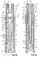
- FIG. 2a inside the body 3 via its open end 5, is introduced an element 20, subsequently qualified as a movable member.
- the movable member 20 is surmounted by a transverse actuating surface 21 of a member which will be generally designated by the reference 90.
- the movable member 20 and the actuating member 90 are elements distinct, they are then preferably made of different materials.
- the movable member 20 comprises means for being mounted integral with the member actuator 90.
- the movable member 20 is force-fitted into a complementary relief 91 of the actuating member 90.
- the movable member 20 and the actuating member 90 protrude from the end open 5.
- the actuating member 90 protrudes by one height H1 relative to a edge 92 defining the opening 5.
- Figure 2c it protrudes by a height H2 less than the first height H1.
- the actuating member 90 comprises a skirt 93 surrounding the movable member 20, this skirt 93 being traversed, in its continuously visible part, always protruding from the open end 5, through a dispensing orifice 7.
- This orifice distribution 7 opens at a recess 8 on the outer periphery of this wall. It is from this orifice 7 that the product is sprayed.
- the bottom 4 is preferably provided with an element 10 extending axially the along the X axis in the container 2, towards the open end 5.
- the organ mobile 20 preferably comprises a hollow tubular side skirt 22 disposed inside the container 2. This skirt 22 has an inside diameter slightly greater than an outside diameter of the element 10. It is also mounted on the less in part around this element 10. When the movable member 20 is moved between the first and second position, at least one section of this skirt slides along element 10.
- a supply channel 27 is thus defined inside the skirt 22, in particular between this skirt 22 and the element 10.
- This supply channel 27 opens into a upper part of the skirt 22.
- a radial passage 30 crossing the thickness of the skirt 22 makes it possible to connect the supply passage 27 to outlet 7.
- the supply channel 27 preferably has a reduced total volume, and at this effect, the actuating member 90 generally comprises a protuberance descending inside this skirt 22 to reduce the interior volume.
- This outgrowth is preferably the complementary relief 91.
- this protuberance corresponds to the complementary means allowing the fixation of the movable member 20 on the actuating member 90.
- the device 1 is preferably provided with an opening system and closure 29 of this supply channel 27.
- This system 29 is obtained by a cooperation between a first plea 95 presented on the inner periphery 96 of the skirt 22 and a second means 97 presented on an outer periphery 98 of element 10.
- the respective heights of these two means are determined, relative to the positions that the skirt 22 can take along the X axis because displacements of the actuating member 90 between the first position and the second position.
- the first means 95 consists in provide the skirt 22 with an inner wall of variable inner diameter depending on the section relative to the X axis considered.
- the second plea 97 corresponds then to an annular lateral projection 97 presented on the element 10 for come into contact with the inner wall 96, depending on the position of this skirt 22 along the X axis.
- the skirt 22 then has in a lower part 99 of inner diameter smaller than the diameter of a higher intermediate portion 11, relative to the X axis.
- the lateral projection 97 comes into contact with the lower part 99, while in the second position, Figure 2c, the lateral projection 97 is no longer in contact with the interior wall 96, and the system 29 is open.
- the lateral projection 97 is possibly opposite the part 11.
- the interior wall at the level of part 11 can comprise for example longitudinal grooves to allow limited opening of the system 29.
- a growth is presented on the inner periphery 96 of the skirt 22 to cooperate with the outer wall 98 of element 10, this wall having sections of variable diameter, and or smooth and or ribbed parts.
- the movable member 20 comprises on an outer periphery 101 of its skirt 22 a lip 100 coming to the contact of an inner wall 12 of the body 3 delimiting the container 2, in particular at proximity to the bottom 4, and more particularly only when moving the first to the second position.
- This inner wall 12 can be presented by the cylindrical inner periphery of the body 3, or a relief arranged in this inner circumference, or a tubular portion 102 protruding from the bottom 4, possibly attached to the body 3.
- the inside diameter defined by this inside wall 12 decreases as it approaches the background orthogonal to the X axis.
- the movable member 20 When moving from the first position to the second position, the movable member 20 is lowered relative to the axis X, and to the body 3 which remains fixed. During this descent, as we saw previously, the outgrowth 97 cooperates with the inner periphery 96 of the skirt 22, and in parallel, the lip 100 also comes to cooperate with the inner wall 12.
- the lip 100 comes first in contact with the inner wall 12, while the system 29 is still closed, and that the protrusion 97 maintains hermetic contact with the element 10.
- the device being used "head up", the product contained in the tank is stored, under the effect of gravity, at the bottom 4.
- the cooperation of the lip 100 with the inner wall 12 allows a dose of product to be isolated in the chamber temporary C determined between this lip 100 and the system 29 still closed.
- This temporary chamber C is formed from an intermediate position, between the first position and the second position, of the movable member 20, cf. Figure 2b. When moving from the first position to the second, you reach the intermediate position from the moment the lip 100 comes into contact with the inner wall 12.
- the lip 100 remains in contact with the interior wall 12, and the pressure rises in this temporary chamber C.
- the lip 100 still being in tight contact with the inner wall 12, the product is then ejected under pressure into the channel 27, the radial passage 30 and finally through the dispensing orifice 7.
- the ejection of the liquid begins before reaching the second position. Indeed, the opening of the system 29 is provided from close positions but slightly anticipated in relation to reaching the second position.
- the lip 100 remains in contact with the wall intermediate 12, and the contact pressure may possibly increase. It is in the same way during the ascent movement, where the lip 100 remains in contact with the interior wall 12 until it again reaches this intermediate position. Beyond this intermediate position and until finding the first position, the lip 100 is detached from the wall 12, the chamber temporary has disappeared, and the product is again distributed evenly at the bottom of the container 2.
- the lip 100 has a certain hold. in the product so as not to deform under the product flow during movements between the first and second position.
- lip 100 is defined so as to form a slightly flared skirt from top to bottom around the movable member 20. And concerning the first embodiment, the wall 12 offers a chamfered wall narrowing the inside diameter of the container 2 approaching the bottom 4. Regarding the third and fourth embodiments, the lip 100 cooperates with an inner wall of the portion tubular 102 protruding from the bottom 4. This tubular portion 102 can be presented on an insert closing the bottom 4.
- the lip 100 is integrated into the outer periphery 101 of the skirt 22 and it is a boss annular 103 presented by the inner wall 12 which ensures contact watertight with the smooth outer wall 101 of the skirt 22.
- the device 1 comprises an elastic return means 6, to cause the automatic return of the movable member 20 from the second position to the first position.
- This spring 6 is, according to a first embodiment Figures 2a-2e, presented by the actuator 90 and cooperates with a outer lateral periphery 104 of the bottom 4.
- the spring 6 is presented by the movable member 20.
- the spring 6 is immersed in the product and preferably cooperates with the bottom 4, as shown below.
- the spring 6 is presented by the bottom 4, and in particular a element attached to this background 4; it then cooperates with the movable member 20, and can also be immersed in the product.
- the movable member 20 is designed to fit tightly and tightly inside the body 3. It has on its outer periphery 101 an annular upper lip 25 turned downwards, slightly widening outwards so as to be in sealed engagement with the inner wall 12 of the body 3.
- the push button 30 has a lip such as 25 to ensure the same sealing function with the inner wall 12.
- the upper annular lip 25 delimits above the bottom 4 a volume 80 which, in this position, is maximum.
- this volume 80 contains a fraction of product and a fraction of air.
- the radial passage 30 opens into a recess in the external surface of the side skirt 22. In assembled position of the assembly, this recess is centered on the orifice of distribution 7 and defines with the internal surface of the actuating member 90, a plurality of vortex channels 32 in communication with the orifice spraying 7 and with the radial passage 30.
- a snap can be provided between the movable member 20 and the body 3, and or between the actuating member 90 and this body 3 of the container, so as to improve the respective attachment of one to the other.
- the consumer exercises an axial pressure on the surface 21 of the actuating member 90.
- the spring 6 compresses, and the movable member 20 descends with its upper annular lip 25 in sealed engagement with the wall inside 12 of body 3, while lip 100 is not yet in contact with this wall 12.
- the volume 80 defined between the bottom 4 and the movable member 20, decreases and the product contained therein is pressurized and rises, if not already the case, up to the level of the opening / closing system 29 which is still in the closed position.
- this system 29 is provided for sufficiently low relative to the X axis so that the only displacement from the first position to the second position guarantees a rise of the product up to the height of the system 29, regardless of the volume of product remaining in the container. This provision ensures that the temporary room will train each actuation of a dose of a reproducible volume of product.
- volume B and volume of chamber C added together are equal to volume 80.
- the system 29 switches to open position, the product from the temporary chamber is ejected into the channel inlet 27, rushes into the radial passage 30, the vortex channels 32, and is sprayed via the dispensing orifice 7.
- the second position is defined by an arrival in abutment 105 of the member actuator 90, or of the movable member 20, against a part 106 of the body 3.
- the inner wall 12 may include a lug 200, for example in the form of a protrusion longitudinal and radially protruding towards the inside of the body 3, making it possible to locally modify the inner periphery of container 2 so as to disengage locally the upper annular lip 25 of this inner wall 12. The contact watertight is then broken by the passage of this lug 200.
- the lug 200 is chamfered in such a way that it is crossed when passing from the first position to the second and vice versa allows the detachment of the upper lip 25 of the inner wall 12.
- the lug 200 is expected close to reaching the second position, between the position intermediate and the second decision, the upper lip 25 preferably not detached only from the moment when the first lip 100 is in contact with the inner wall 12 and that the intermediate chamber C is formed.
- this lug 200 has a shape of "grain of rice", and the inner wall 12 has several lugs such as 12 regularly spaced at an annular level of the body 3.
- the return means elastic 6 is configured in the form of a helical spring.
- FIG. 5B corresponding to a view of the spring 6 in the state compressed relative to FIG. 5A, the spring 6 is configured in the form of a stacking of several rings 61, 62, 63, 64, 65. Two consecutive rings 61, 62 are kept at a distance from each other by two spacers 66, 67 diametrically opposed, while the rings 62 and 63 are kept at distance from each other by two spacers 58, 69, offset by 90 ° relative to to the spacers 66, 67, and so on over the entire stack.
- the rings 61-65 of the stack get closer two by two to each other, with a maximum approximation, or even a contact, in places located 90 ° from to the spacers.
- the stack compresses uniformly.
- the spring 6 is obtained by molding a material thermoplastic, to limit its wear over time, and in particular to avoid any creep of the spring structure, before the very first use, the spring 6 is placed in the container 2 in an uncompressed state.
- the device 1 can therefore be stored for a long period without losing its functionality. Even if the first use does not occur until two years after conditioning of such a device 1, the operation of the spring 6 will still be optimum, its elasticity has never been sought before.
- the life of such device after first use being short, for example of the order of two month, the spring 6 can be kept at least slightly compressed, while with optimum functioning.
- an outer periphery 114 of the movable member comprises at least a double curved annular profile 115, 116 to cooperate with a notch latching 117 presented on the inner wall 12.
- this notch 117 is presented on a wider section of the wall 12 diameter than the section against which the upper annular lip 25 applies.
- the double profile is preferably made so as to form two bulges 115 and 116, at two height levels differing relative to the X axis.
- FIG. 2a the device 1 is shown before the very first use, the latching notch 117 being blocked between the two annular profiles 115 and 116.
- the advantage of the double annular profile is that it makes it possible to block the position of the movable member 20 relative to the container 2 before said first use.
- the upper annular profile 116 is driven in force under the detent notch 117. From this crossing, the spring 6 is then compressed.
- a high position of the movable member 20, after this first use, Figure 2e will correspond to a position in which the annular profile upper 116 is in abutment under the detent notch 117, relative to the axis X.
- the movable member 20 will protrude a little less from the container 2 after this first use.
- the respective positions of the catch 117 and the annular profiles 115 and 116 can be reversed, the latching notch being then provided on the movable member 20 and the double annular profile on the wall interior 12.
- the latching notch can form a rod snap ring and the double profile can be formed by two notches annulars to cooperate with said annular snap ring.
- this preliminary storage position, before the first use, can also be blocked by a material bridge (not shown) formed between the container 2 and the movable member 20, this material bridge being able to be broken during the first use.
- the spring according to the configuration which has just been described with reference to FIGS. 5A and 5B can also be used for all the embodiments of all of which will be described later.
- the device 1 according to the invention is equipped with means 50 to guarantee the tightness of the dispensing orifice 7, even before the first use.
- This means 50 makes it possible to increase the sealing guarantees already conferred by the system 29 which is closed in this position at rest.
- This way 50 is initially sealed inside the skirt 22, above the element 10.
- This medium 50 can also be a plug force-fitted inside the skirt 22.
- This means 50 must leave a passage for the product in the supply channel 27 from the first pressure exerted on the actuating member 90.
- the means 50 being, during this first actuation, still integral with the skirt 22, the latter is driven towards the element 10.
- the element 10 comes into contact with the medium 50, a slight resistance is felt at the surface 21.
- the user must then provide a slightly more pressure strong so that the connection between the means 50 and the inner periphery of the skirt 22 is breaks, or so that the means 50 is pushed back into an area of the skirt 22 of wider inside diameter.
- the means 50 is then free in this zone, and during movements of the movable member 20 from the first position to the second, the means 50 does not completely block the supply channel 27.
- the means 50 is formed by a plug, as is shown in Figure 2a, it preferably has a chamfered shape such that its widest outer rim is in leaktight contact at a level of the rim interior 96 of skirt 22.
- This interior periphery 96 preferably comprises, above from this level of contact, an elastically deformable corolla 107 that can pass through the means 50 when it is pushed back by the element 10 upwards inside the skirt 22.
- the means 50 can be formed from a film arranged transversely, sealingly, in contact with the inner periphery of the skirt 22, this film being able to be pierced by the element 10, which then comprises a point 108, so as to break the seal and permanently clear the channel 27, from the first actuation.
- the means 50 can be formed by a plug of the type shown in Figure 2a, but here the cap is of a length such that in cooperation with element 10, this cap 50 can be pushed back against a complementary means 109 of the organ 90, on which it can be held jointly after the first actuation.
- the means 50 has a closed tubular shape on a first side to ensure the initial seal at the interior wall 12, and open on an opposite side to cooperate with the complementary means 109.
- Element 10 repels this means 50 by resting on the first side closed 110, so that the complementary means 109 is inserted in force, on the open side 111, inside this tubular shape.
- This variant allows to control the position of this means 50 in the supply channel 27, in particular to immobilize it definitively for the subsequent displacements of the actuator between the first and second positions.
- the presence of the sealing means 50 allows filling "upside down" of the container 2, the actuating member 90 and the movable member 20 being already mounted in the body 3, this body 3 having an opening for the filling at the bottom 4.
- a cap is provided to close this filling opening.
- the upper annular skirt 25 also provides a tight seal between the body 3 and the movable member 20.
- the device 1 described above can be produced by modifying the position of the spring 6, and or by modifying the way in which the temporary room is formed, and or by modifying the position or structure of the annular lip upper 25, and or by modifying the initial sealing system 50, and or modifying the internal structure of the container 2.
- the bottom 4 is fixed to the body 3 by snap-fastening.
- Spring 6 is obtained from molding with the movable member 20, it is immersed in the product.
- Spring 6 is surmounted a tubular portion 112 connected at the level of a flat 113 to a second tubular portion forming the skirt 22, this second tubular portion is disposed inside the first tubular portion and even has a part extending inside the turns of the spring 6.
- the skirt 22 is long such that one of its ends is intended to be immersed in the product, at least in the second position.
- the actuator 90 with its external side skirt 91 below the actuating surface 21 also has an upper annular lip such as 25 on its outer periphery 114 to seal the container 2.
- the radial passage 30 is formed directly between the flat 113 of the movable member 20 and the actuating surface 21.
- the actuating member comprises at least the double curved annular profile 115, 116 to cooperate with the notch latching 117 presented on the inner wall 12.
- this notch latching is presented on a section of the wall 12 of larger diameter that the section against which the upper annular lip 25 applies.
- the double profile is preferably made so as to form two bulges 115 and 116, at two height levels differing relative to the X axis.
- Figure 3a the device 1 is presented before any first use, a first annular profile 115 being blocked under the latching catch 117. The movable member is then blocked in the container 2, between the bottom 4 and the actuating member 90.
- the means 50 is arranged in a sealed manner to inside the tubular skirt 22.
- the bottom 4 comprises a tubular portion 102 rising relative to the bottom 4, inside the container 2.
- the element 10 is also standing in the middle of this tubular portion 102.
- This tubular portion 102 makes it possible to propose locally a mini-container with a diameter much smaller than that of the body 3.
- It further comprises an annular bead 103 on its inner periphery, and thus forms the equivalent of the inner wall 12 intended to cooperate with the outer periphery 101 of the skirt 22.
- the annular bead 103 is in contact with the outer periphery 101 of the skirt 22, the element 10 has definitively pushed the medium 50 on the complementary means 109.
- the inner periphery 96 of the skirt 22 is not in leaktight contact with the outer periphery 98 of the element 10, this which places the system 29 in the open position. Besides a spray of product is obtained.
- the outer periphery 101 of the skirt comes first into contact with the inner bead 103, and at this time the inner periphery 96 of the skirt 22 is still in sealed contact with the element 10 to keep the system 29 closed. Only near the second position, the element 10 comprising a section 118 of smaller diameter at near the bottom 4, the inner periphery 96 of the skirt 22 then being opposite with this portion 118, the system 29 is opened and the product sprayed.
- the advantage of this embodiment is that it makes it possible to present the body 3 to the interior of which are already mounted the actuating member 90 and the movable member 20 under a filler which then deposits, in container 2 "upside down", a defined volume of product. And all that remains is to mount the attached plug to form the bottom 4 and finish making the device 1.
- the movable member 20 is mounted in the skirt lateral lateral 91 of the actuating member so that a seal sealing 119 is formed between the actuating member 90 and the movable member 20, well below the level where hole 7 is made.
- the body 3 comprises an attached bottom 4 which has inside the container a spring means 6 with which it is obtained from molding.
- This added back also includes the element 10 of substantially cylindrical shape erected in the container 2, and a portion tubular so as to locally decrease the internal diameter of the body 3.
- the spring 6 comes to bear against a flange protruding from a periphery outside of the skirt 22 formed by the movable member 20. Of this flange exceed two inversely flared skirts. A first flared skirt from the top downward defines the upper annular skirt 25, while a second skirt flared 120 from bottom to top defines a bulge intended to cooperate with a latching notch 117 proposed on the inner wall 12 of the body 3.
- the second flared skirt passes under the detent notch 117.
- the spring 6 is compressed until a temporary chamber is formed between on the one hand the end of the lip 100 of the skirt 22, and on the other hand the closed system 29.
- the system 29 is obtained by cooperation between the interior wall 96 of the skirt 22 and the outer periphery 98 of the element 10.
- This inner wall 96 and the periphery exterior 98 have reliefs 95 and 97 respectively or alternately to be in tight contact with each other in at least certain positions relative to the X axis.
- the fourth embodiment, Figure 6a constitutes a faithful variant of the third embodiment, with the difference that the flange protruding from the outer periphery of the skirt 22 has only one slightly flared skirt so as to define only the upper lip 25.
- the detent notch 117 is then provided on the inner periphery of the container 2 according to this fourth embodiment for cooperating with a double profile presented on the periphery outside of the actuating member 90 which is here provided to descend at least partially in container 2.
- the device can be equipped with at least one second spring whose compression force is preferably different from that of the means of elastic return 6.
Landscapes
- Engineering & Computer Science (AREA)
- General Engineering & Computer Science (AREA)
- Mechanical Engineering (AREA)
- Containers And Packaging Bodies Having A Special Means To Remove Contents (AREA)
- Closures For Containers (AREA)
Abstract
Description
- la figure 1 montre une vue assemblée d'un dispositif 1 selon l'invention;
- les figures 2a, 2b, 2c, 2d et 2e illustrent un premier mode de réalisation d'un ensemble de conditionnement et de distribution à différentes étapes de la distribution d'une dose de produit;
- les figures 3a, 3b, 3c sont relatives à un second mode de réalisation de l'ensemble de conditionnement et de distribution selon l'invention à différentes étapes de la distribution d'une dose de produit;
- les figures 4a, 4b, 4c sont relatives à un troisième mode de réalisation de l'ensemble de conditionnement et de distribution selon l'invention à différentes étapes de la distribution d'une dose de produit;
- les figures 5a et 5b sont relatives à une variante de réalisation d'un ressort disposé dans un tel ensemble de conditionnement et de distribution selon l'invention;
- figure 6a est relative à un quatrième mode de réalisation de l'ensemble de conditionnement et de distribution selon l'invention avant une première utilisation.
- une première position, au repos, représentée sur les Figures 2a, 3a, et 4a, et
- une deuxième position, dite "enfoncée", dans laquelle la pulvérisation d'une dose de produit peut être obtenue, sur les figures 2c, 3b et 4b.
Claims (25)
- Ensemble (1) pour le conditionnement et la distribution d'un produit, notamment cosmétique, ledit ensemble comprenantcaractérisé en ce que l'organe mobile comporte une lèvre supérieure (25) apte à s'appliquer de manière étanche contre ladite paroi intérieure sur au moins une partie de son mouvement de la première position vers la seconde position, la coopération entre la première lèvre et la paroi intérieure permettant, au moins lors de la première utilisation, d'isoler une fraction dudit produit et de comprimer cette fraction de manière à en provoquer la sortie au travers d'au moins un orifice de distribution (7), le retour de l'organe mobile de la seconde position vers la première, lorsque cesse la commande d'actionnement, s'accompagnant d'une entrée d'air à l'intérieur du récipient.i) un récipient (2) contenant le produit, le récipient étant délimité par un corps (3) dont une extrémité est fermée par un fond (4) ;ii) un organe (20) mobile relativement au corps du récipient et apte, en réponse à une commande exercée manuellement sur une surface (21) d'un organe d'actionnement (90), à passer d'une première position dans laquelle une première lèvre (100, 101) de l'organe mobile est à distance non nulle d'une paroi intérieure (12, 102), à une seconde position dans laquelle la première lèvre est en engagement avec ladite paroi intérieure,
- Ensemble (1) selon la revendication 1, caractérisé en ce qu'il comporte un moyen (50) pour assurer l'étanchéité avant la première utilisation, ce moyen pouvant être rendu solidaire (109) de l'organe d'actionnement après le premier actionnement.
- Ensemble (1) selon l'une des revendications 1 à 2, caractérisé en ce que l'orifice de distribution (7) est en communication sélective, via un système d'ouverture/fermeture (29), avec au moins un canal d'amenée (27) en communication avec la dose de produit à l'intérieur du récipient.
- Ensemble (1) selon la revendication 3, caractérisé en ce que le canal d'amenée (27) est délimité entre un élément (10) solidaire du corps du récipient, notamment obtenu de moulage avec ce dernier, et une jupe (22) solidaire de l'organe mobile, notamment obtenu de moulage avec ce dernier.
- Ensemble (1) selon l'une des revendications 3 à 4, caractérisé en ce que le système d'ouverture/fermeture (29) est formé par la coopération d'un élément (10) solidaire du corps du récipient, notamment obtenu de moulage avec ce dernier, et d'un élément solidaire (22) de l'organe mobile, notamment obtenu de moulage avec ce dernier.
- Ensemble (1) selon l'une des revendications 1 à 5, caractérisé en ce que la première lèvre est soumise à une contrainte élastique augmentant en direction de la seconde position.
- Ensemble (1) selon l'une des revendications 1 à 6, caractérisé en ce que le récipient présente un rétrécissement de son pourtour intérieur, notamment à proximité du fond, la première lèvre venant au contact de ce rétrécissement.
- Ensemble (1) selon l'une des revendications 1 à 7, caractérisé en ce que la paroi intérieure (12) est de section transversale circulaire, la première lèvre (100) étant annulaire, la distance entre un axe longitudinal (X) de l'ensemble et ladite paroi intérieure diminuant, de préférence progressivement, en direction du mouvement de la première position vers la seconde.
- Ensemble (1) selon l'une des revendications 1 à 8, caractérisé en ce que la paroi intérieure du récipient comporte une deuxième lèvre pour coopérer avec un élargissement du pourtour extérieur (101) de l'organe mobile, l'organe mobile étant configuré de sorte que, sur au moins une partie de son mouvement entre lesdites première et seconde positions, la deuxième lèvre est en contact étanche avec ce pourtour extérieur (101).
- Ensemble (1) selon l'une des revendications 1 à 9, caractérisé en ce que la dose est reproductible et correspond par exemple à un volume de 1/10ème à 1/20éme du volume de produit contenu dans le récipient.
- Ensemble (1) selon l'une des revendications 1 à 10, caractérisé en ce que le volume de produit contenu initialement dans le récipient correspond à un volume de 1/3 à 2/3 du volume intérieur (80) défini dans la première position entre l'organe mobile et le fond du récipient.
- Ensemble (1) selon l'une des revendications 1 à 11, caractérisé en ce que la lèvre supérieure garantit l'étanchéité du réservoir dans la première position.
- Ensemble (1) selon l'une des revendications 1 à 12, caractérisé en ce que l'entrée d'air à l'intérieur dudit volume se fait par au moins un passage formé entre l'organe mobile et la paroi intérieure du récipient, et notamment un passage ménagé entre la lèvre supérieure et la paroi intérieure.
- Ensemble (1) selon l'une des revendications 1 à 13, caractérisé en ce que la paroi intérieure comporte un ergot (200) configuré pour rompre le contact étanche réalisé avec la lèvre supérieure, suite à son franchissement au moins lors du passage de la seconde position à la première.
- Ensemble (1) selon l'une des revendications 1 à 14, caractérisé en ce que le retour de l'organe mobile (20) de la seconde position vers la première résulte de l'action d'un moyen de rappel élastique (6).
- Ensemble (1) selon la revendication 15, caractérisé en ce qu'une extrémité du moyen de rappel élastique est en butée contre le fond du récipient.
- Ensemble (1) selon l'une des revendications 15 à 16, caractérisé en ce que le moyen de rappel élastique (6) est obtenu de moulage avec le corps du récipient, et ou avec l'organe d'actionnement, et ou l'organe mobile disposé entre le récipient et l'organe d'actionnement.
- Ensemble (1) selon l'une des revendications 15 à 17, caractérisé en ce que le moyen de rappel élastique (6), ainsi que tout élément obtenu de moulage avec ce dernier, est réalisé en POM ou en polypropylène ou en polyéthylène.
- Ensemble (1) selon l'une des revendications 15 à 18, caractérisé en ce que le moyen de rappel élastique (6) est configuré sous forme d'un empilement d'au moins trois anneaux (61-65) reliés deux à deux via deux entretoises (66) diamétralement opposées, les entretoises (66) séparant un premier anneau (61) d'un second anneau (62) adjacent au premier étant décalées à 90° par rapport aux entretoises (68, 69) séparant le second anneau (62) d'un troisième anneau (63) adjacent au second et disposé du côté du second opposé au premier.
- Ensemble (1) selon l'une des revendications 15 à 16, caractérisé en ce que le moyen de rappel élastique (6) est constitué d'un ressort rapporté (406), notamment en plastique ou en métal.
- Ensemble (1) selon l'une des revendications 1 à 20, caractérisé en ce que l'organe mobile (20), et en particulier la première lèvre (100), est réalisé en au moins une polyoléfine, notamment un polyéthylène.
- Ensemble (1) selon l'une des revendications 1 à 21, caractérisé en ce que le fond du récipient est un fond rapporté, la fixation du fond sur le corps du récipient étant obtenue notamment par encliquetage, vissage, collage ou soudage.
- Ensemble (1) selon l'une des revendications 1 à 22, caractérisé en ce que l'orifice de distribution est alimenté par une pluralité de canaux à effet tourbillonnaire (32).
- Ensemble (1) selon l'une des revendications 1 à 23, caractérisé en ce qu'avant la première utilisation, le moyen de rappel élastique est non comprimé dans le récipient.
- Ensemble (1) selon l'une des revendications 1 à 24, caractérisé en ce que le récipient comporte un cran d'encliquetage (117) destiné à coopérer avec un profil complémentaire (115, 116) de l'organe mobile de manière à immobiliser cet organe mobile relativement au récipient avant la première utilisation.
Applications Claiming Priority (2)
| Application Number | Priority Date | Filing Date | Title |
|---|---|---|---|
| FR0305901A FR2854821B1 (fr) | 2003-05-16 | 2003-05-16 | Ensemble pour le conditionnement et la distribution d'un produit, notamment sous forme d'un echantillon |
| FR0305901 | 2003-05-16 |
Publications (2)
| Publication Number | Publication Date |
|---|---|
| EP1477234A2 true EP1477234A2 (fr) | 2004-11-17 |
| EP1477234A3 EP1477234A3 (fr) | 2008-12-17 |
Family
ID=33017185
Family Applications (1)
| Application Number | Title | Priority Date | Filing Date |
|---|---|---|---|
| EP04291007A Withdrawn EP1477234A3 (fr) | 2003-05-16 | 2004-04-15 | Ensemble pour le conditionnement et la distribution d'un produit, notamment sous forme d'un échantillon |
Country Status (6)
| Country | Link |
|---|---|
| US (1) | US6948639B2 (fr) |
| EP (1) | EP1477234A3 (fr) |
| CN (1) | CN1310806C (fr) |
| BR (1) | BRPI0402042A (fr) |
| FR (1) | FR2854821B1 (fr) |
| RU (1) | RU2277501C2 (fr) |
Cited By (4)
| Publication number | Priority date | Publication date | Assignee | Title |
|---|---|---|---|---|
| ES2265789A1 (es) * | 2006-03-02 | 2007-02-16 | Saint-Gobain Calmar, S.A. | Bomba pulverizadora aplanada. |
| FR2956649A1 (fr) * | 2010-02-24 | 2011-08-26 | Valois Sas | Organe de distribution de produit fluide et dispositif de distribution de produit fluide comportant un tel organe. |
| WO2014081746A1 (fr) | 2012-11-23 | 2014-05-30 | 3M Innovative Properties Company | Valve de distribution de dose mesurée |
| WO2020156935A1 (fr) * | 2019-01-29 | 2020-08-06 | Rpc Bramlage Gmbh | Distributeur destiné à distribuer des matières coulantes, par exemple des matières liquides ou pâteuses |
Families Citing this family (53)
| Publication number | Priority date | Publication date | Assignee | Title |
|---|---|---|---|---|
| US8512718B2 (en) | 2000-07-03 | 2013-08-20 | Foamix Ltd. | Pharmaceutical composition for topical application |
| IL152486A0 (en) | 2002-10-25 | 2003-05-29 | Meir Eini | Alcohol-free cosmetic and pharmaceutical foam carrier |
| US7700076B2 (en) | 2002-10-25 | 2010-04-20 | Foamix, Ltd. | Penetrating pharmaceutical foam |
| US8900554B2 (en) | 2002-10-25 | 2014-12-02 | Foamix Pharmaceuticals Ltd. | Foamable composition and uses thereof |
| US10117812B2 (en) | 2002-10-25 | 2018-11-06 | Foamix Pharmaceuticals Ltd. | Foamable composition combining a polar solvent and a hydrophobic carrier |
| US9211259B2 (en) | 2002-11-29 | 2015-12-15 | Foamix Pharmaceuticals Ltd. | Antibiotic kit and composition and uses thereof |
| US9668972B2 (en) | 2002-10-25 | 2017-06-06 | Foamix Pharmaceuticals Ltd. | Nonsteroidal immunomodulating kit and composition and uses thereof |
| US7704518B2 (en) | 2003-08-04 | 2010-04-27 | Foamix, Ltd. | Foamable vehicle and pharmaceutical compositions thereof |
| US8486376B2 (en) | 2002-10-25 | 2013-07-16 | Foamix Ltd. | Moisturizing foam containing lanolin |
| US9265725B2 (en) | 2002-10-25 | 2016-02-23 | Foamix Pharmaceuticals Ltd. | Dicarboxylic acid foamable vehicle and pharmaceutical compositions thereof |
| US7820145B2 (en) | 2003-08-04 | 2010-10-26 | Foamix Ltd. | Oleaginous pharmaceutical and cosmetic foam |
| ES2532906T5 (es) | 2002-10-25 | 2022-03-23 | Foamix Pharmaceuticals Ltd | Espuma cosmética y farmacéutica |
| US20080138296A1 (en) | 2002-10-25 | 2008-06-12 | Foamix Ltd. | Foam prepared from nanoemulsions and uses |
| US7575739B2 (en) | 2003-04-28 | 2009-08-18 | Foamix Ltd. | Foamable iodine composition |
| FR2854822B1 (fr) * | 2003-05-16 | 2005-06-24 | Rexam Dispensing Sys | Distributeur de produit liquide ou en gel |
| US8486374B2 (en) | 2003-08-04 | 2013-07-16 | Foamix Ltd. | Hydrophilic, non-aqueous pharmaceutical carriers and compositions and uses |
| US8795693B2 (en) | 2003-08-04 | 2014-08-05 | Foamix Ltd. | Compositions with modulating agents |
| ITMI20060151A1 (it) * | 2006-01-30 | 2007-07-31 | Microspray Delta Spa | Pulsante per pompetta con una sua piorzione di azionamento mobile rispetto ad una porzione avente un ugello o pastiglia di erogazione e degli elementi per il suo ritegno sulla pompetta |
| EP1834703A3 (fr) * | 2006-03-13 | 2008-11-05 | Ing. Erich Pfeiffer GmbH | Distributeur de produit fluide |
| FR2901256A1 (fr) * | 2006-05-18 | 2007-11-23 | Frederic Platel | Dispositif vaporisateur-doseur |
| US20080260655A1 (en) | 2006-11-14 | 2008-10-23 | Dov Tamarkin | Substantially non-aqueous foamable petrolatum based pharmaceutical and cosmetic compositions and their uses |
| US8060949B2 (en) * | 2007-07-20 | 2011-11-22 | Maverik Lacrosse, Llc | Protective sports glove |
| US8636982B2 (en) | 2007-08-07 | 2014-01-28 | Foamix Ltd. | Wax foamable vehicle and pharmaceutical compositions thereof |
| US8617100B2 (en) | 2007-09-04 | 2013-12-31 | Foamix Ltd. | Device for delivery of a foamable composition |
| FR2922533B1 (fr) * | 2007-10-23 | 2011-08-05 | Rexam Dispensing Sys | Flacon comprenant un moyen rapporte de liaison |
| TW201513903A (zh) * | 2007-11-29 | 2015-04-16 | Glaxo Group Ltd | 施配裝置 |
| US9439857B2 (en) | 2007-11-30 | 2016-09-13 | Foamix Pharmaceuticals Ltd. | Foam containing benzoyl peroxide |
| WO2010041141A2 (fr) | 2008-10-07 | 2010-04-15 | Foamix Ltd. | Support expansible à base d’huile et préparations |
| WO2009090495A2 (fr) | 2007-12-07 | 2009-07-23 | Foamix Ltd. | Vecteurs moussants siliconés à base d'huile et de liquide, et formulations |
| WO2009090558A2 (fr) | 2008-01-14 | 2009-07-23 | Foamix Ltd. | Compositions pharmaceutiques pouvant mousser de poloxamère avec des agents actifs et/ou des cellules thérapeutiques, et utilisations |
| TWI483780B (zh) * | 2008-09-11 | 2015-05-11 | Gojo Ind Inc | 具有用於與分配器接合的可撓機構之泵 |
| CA2760186C (fr) | 2009-04-28 | 2019-10-29 | Foamix Ltd. | Vehicule moussant et compositions pharmaceutiques comportant des solvants polaires aprotiques et leurs utilisations |
| WO2011013009A2 (fr) | 2009-07-29 | 2011-02-03 | Foamix Ltd. | Compositions hydro-alcooliques moussantes non tensioactives, mousses légères, et leurs utilisations |
| CA2769677A1 (fr) | 2009-07-29 | 2011-02-03 | Foamix Ltd. | Compositions hydro-alcooliques moussantes a base d'agents non tensioactifs non polymeres, mousses legeres, et leurs utilisations |
| US9849142B2 (en) | 2009-10-02 | 2017-12-26 | Foamix Pharmaceuticals Ltd. | Methods for accelerated return of skin integrity and for the treatment of impetigo |
| CA2776474C (fr) | 2009-10-02 | 2021-01-12 | Foamix Ltd. | Compositions de tetracycline a usage topique |
| WO2012007843A2 (fr) | 2010-07-12 | 2012-01-19 | Foamix Ltd. | Appareil et procédé pour éjecter une dose unitaire de contenu d'un récipient |
| FR2966129B1 (fr) * | 2010-10-18 | 2012-10-19 | Rexam Dispensing Sys | Procede et flacon de distribution d'un produit fluide |
| FR2976270B1 (fr) * | 2011-06-08 | 2013-06-28 | Rexam Dispensing Sys | Flacon de distribution d'un produit fluide |
| CN202321216U (zh) * | 2011-12-14 | 2012-07-11 | 东莞怡信磁碟有限公司 | 一种可充式喷液瓶 |
| JP5986643B2 (ja) | 2012-01-20 | 2016-09-06 | ドクター ピー インスティチュート エルエルシー | 一体成形された閉止具、一方向弁、可変容積貯蔵チャンバ、および急速噴出防止特徴部を備えるデバイスならびに関連する方法 |
| GB201210580D0 (en) * | 2012-06-14 | 2012-08-01 | 3M Innovative Properties Co | Metered dose dispensing valve |
| JP6144099B2 (ja) * | 2013-04-25 | 2017-06-07 | 株式会社丸一 | ポンプ式噴霧容器の外気導入機構 |
| FR3008396B1 (fr) * | 2013-07-10 | 2016-05-06 | Axilone Plastique | Distributeur, poseur, applicateur de creme rechargeable portatif. |
| WO2015105716A2 (fr) * | 2014-01-13 | 2015-07-16 | Meadwestvaco Corporation | Pompe de distribution avec ressort à jupe |
| DE202014103984U1 (de) * | 2014-03-10 | 2015-06-12 | Rpc Bramlage Gmbh | Spender |
| WO2015164633A1 (fr) * | 2014-04-23 | 2015-10-29 | Israel Olegnowicz | Verrou intégré pour atomiseur |
| USD763703S1 (en) * | 2015-05-12 | 2016-08-16 | Sin-Hsiung Chen | Bottle for cosmetics |
| MX2017011630A (es) | 2016-09-08 | 2018-09-25 | Foamix Pharmaceuticals Ltd | Composiciones y metodos para tratar rosacea y acne. |
| US10751740B2 (en) * | 2019-01-09 | 2020-08-25 | Tessy Plastics Corporation | Eco pump assembly |
| JPWO2021220643A1 (fr) * | 2020-04-30 | 2021-11-04 | ||
| KR102427023B1 (ko) * | 2020-08-24 | 2022-07-29 | 주식회사 삼화 | 액체 분사를 위한 펌프 |
| EP4223178A1 (fr) | 2022-02-02 | 2023-08-09 | samplistick GmbH | Dispositif de remplissage, de transport et de stockage de manière hygiénique d'un produit cosmétique |
Citations (2)
| Publication number | Priority date | Publication date | Assignee | Title |
|---|---|---|---|---|
| FR2393279A1 (fr) | 1977-06-03 | 1978-12-29 | Normos Norbert | Dispositif de prelevement de doses precises et constantes de liquide |
| WO2002094708A1 (fr) | 2001-05-23 | 2002-11-28 | Cohen, Ben, Z. | Pompe doseuse precise |
Family Cites Families (25)
| Publication number | Priority date | Publication date | Assignee | Title |
|---|---|---|---|---|
| US3412907A (en) | 1967-03-07 | 1968-11-26 | William J. Faso | Perfume container and sprayer |
| BE752932A (fr) * | 1969-07-07 | 1970-12-16 | Pulverisation Par Abreviation | Vaporisateur a tube plongeur |
| FR2149669A5 (fr) * | 1971-08-19 | 1973-03-30 | Step | |
| US3897005A (en) | 1972-11-13 | 1975-07-29 | George Reiner | Convenience spray dispensing packet |
| US3940030A (en) * | 1974-08-16 | 1976-02-24 | Hirosi Kondo | Dispenser device for taking out contents |
| US4175704A (en) * | 1976-02-17 | 1979-11-27 | Cohen Milton J | Non-aerosol continuous spray dispenser |
| IT1092596B (it) * | 1978-02-09 | 1985-07-12 | Ruscitti Tommaso | Pompetta a mano per dispensare liquidi micronizzati a pressione prestabilita |
| SE7905979L (sv) | 1978-12-15 | 1980-06-16 | Panpack Ag | Forpackning for upptagning och sprutning av sma vetskemengder |
| US5257726A (en) * | 1985-08-14 | 1993-11-02 | Ing. Erich Pfeiffer Gmbh & Co. Kg | Dispenser for flowable media |
| FR2646408B1 (fr) | 1989-04-28 | 1991-08-30 | Sofab | Conditionnement a distributeur integre |
| FR2649382B1 (fr) * | 1989-07-04 | 1991-10-31 | Aerosols & Bouchage | Distributeurs miniatures |
| FR2650763A1 (fr) * | 1989-08-10 | 1991-02-15 | Bedou Patrick | Vaporisateur portatif rechargeable pour liquides |
| DE4008068A1 (de) * | 1990-03-14 | 1991-09-19 | Pfeiffer Erich Gmbh & Co Kg | Austragvorrichtung fuer medien |
| FR2661157B1 (fr) * | 1990-04-19 | 1993-08-13 | Jumel Bernard | Systeme doseur sans bague destine a etre emmanche a force a l'interieur d'un col de recipient. |
| DE4136826A1 (de) | 1991-11-08 | 1993-05-13 | Pfeiffer Erich Gmbh & Co Kg | Austragvorrichtung fuer medien |
| US5242089A (en) * | 1992-01-29 | 1993-09-07 | Calmar Inc. | Miniature pump sprayer |
| US5277340A (en) * | 1992-11-05 | 1994-01-11 | Risdon Corporation | Dispensing container |
| DE29514644U1 (de) * | 1995-09-12 | 1996-02-01 | Piepenstock Friedhelm | Schraubendruckfeder |
| US5709320A (en) | 1996-07-30 | 1998-01-20 | Jimenez; Ruben | Manual self-defense spray device |
| FR2778639B1 (fr) | 1998-05-18 | 2000-07-28 | Valois Sa | Dispositif de pulverisation du type echantillon |
| US6273301B1 (en) * | 2000-03-29 | 2001-08-14 | Cheng-Yuan Su | Perfume pen assembly structure |
| JP3563014B2 (ja) * | 2000-06-26 | 2004-09-08 | 株式会社トップ | 吐出容器 |
| EP1199106B1 (fr) * | 2000-10-19 | 2004-06-30 | Dentaco Dentalindustrie- und Marketing GmbH | Distributeur-doseur de produit fluide avec une pompe à main intégrée dans le récipient |
| FR2837177B1 (fr) * | 2002-03-15 | 2004-12-03 | Oreal | Ensemble pour le conditionnement et la distribution d'un produit, notamment sous forme d'un echantillon |
| FR2837178B1 (fr) * | 2002-03-15 | 2004-12-03 | Oreal | Ensemble pour le conditionnement et la distribution d'un produit, notamment sous forme d'un echantillon |
-
2003
- 2003-05-16 FR FR0305901A patent/FR2854821B1/fr not_active Expired - Fee Related
-
2004
- 2004-04-15 EP EP04291007A patent/EP1477234A3/fr not_active Withdrawn
- 2004-05-11 BR BR0402042-1A patent/BRPI0402042A/pt not_active IP Right Cessation
- 2004-05-14 CN CNB200410043211XA patent/CN1310806C/zh not_active Expired - Fee Related
- 2004-05-14 RU RU2004114828/12A patent/RU2277501C2/ru not_active IP Right Cessation
- 2004-05-17 US US10/846,519 patent/US6948639B2/en not_active Expired - Fee Related
Patent Citations (2)
| Publication number | Priority date | Publication date | Assignee | Title |
|---|---|---|---|---|
| FR2393279A1 (fr) | 1977-06-03 | 1978-12-29 | Normos Norbert | Dispositif de prelevement de doses precises et constantes de liquide |
| WO2002094708A1 (fr) | 2001-05-23 | 2002-11-28 | Cohen, Ben, Z. | Pompe doseuse precise |
Cited By (10)
| Publication number | Priority date | Publication date | Assignee | Title |
|---|---|---|---|---|
| ES2265789A1 (es) * | 2006-03-02 | 2007-02-16 | Saint-Gobain Calmar, S.A. | Bomba pulverizadora aplanada. |
| US8152077B2 (en) | 2006-03-02 | 2012-04-10 | Meadwestvaco Calmar, Inc. | Flat atomizer pump |
| FR2956649A1 (fr) * | 2010-02-24 | 2011-08-26 | Valois Sas | Organe de distribution de produit fluide et dispositif de distribution de produit fluide comportant un tel organe. |
| WO2011104470A1 (fr) * | 2010-02-24 | 2011-09-01 | Valois Sas | Organe de distribution de produit fluide et dispositif de distribution de produit fluide comportant un tel organe. |
| CN102858467A (zh) * | 2010-02-24 | 2013-01-02 | 阿普塔尔法国简易股份公司 | 流体产品分配机构和包括该类机构的流体产品分配装置 |
| WO2014081746A1 (fr) | 2012-11-23 | 2014-05-30 | 3M Innovative Properties Company | Valve de distribution de dose mesurée |
| WO2020156935A1 (fr) * | 2019-01-29 | 2020-08-06 | Rpc Bramlage Gmbh | Distributeur destiné à distribuer des matières coulantes, par exemple des matières liquides ou pâteuses |
| CN113543891A (zh) * | 2019-01-29 | 2021-10-22 | Rpc布兰姆拉格股份有限公司 | 用于输出可流动的、例如液态或膏状的物料的配料器 |
| CN113543891B (zh) * | 2019-01-29 | 2022-12-20 | Rpc布兰姆拉格股份有限公司 | 用于输出可流动的、例如液态或膏状的物料的配料器 |
| US11612903B2 (en) | 2019-01-29 | 2023-03-28 | Rpc Bramlage Gmbh | Dispenser for dispensing flowable, for example liquid or paste-like, compounds |
Also Published As
| Publication number | Publication date |
|---|---|
| BRPI0402042A (pt) | 2005-03-22 |
| FR2854821A1 (fr) | 2004-11-19 |
| CN1310806C (zh) | 2007-04-18 |
| US20050006412A1 (en) | 2005-01-13 |
| EP1477234A3 (fr) | 2008-12-17 |
| FR2854821B1 (fr) | 2006-12-08 |
| RU2277501C2 (ru) | 2006-06-10 |
| CN1550423A (zh) | 2004-12-01 |
| RU2004114828A (ru) | 2005-10-27 |
| US6948639B2 (en) | 2005-09-27 |
Similar Documents
| Publication | Publication Date | Title |
|---|---|---|
| EP1477234A2 (fr) | Ensemble pour le conditionnement et la distribution d'un produit, notamment sous forme d'un échantillon | |
| EP0954485B1 (fr) | Dispositif de distribution de produit fluide avec systeme d'obturation | |
| EP1344571B1 (fr) | Ensemble pour le conditionnement et la distribution d'un produit, notamment sous forme d'un échantillon | |
| EP0757592B1 (fr) | Pompe a precompression perfectionnee | |
| FR2717447A1 (fr) | Dispositif doseur destiné à délivrer des doses unitaires constantes. | |
| FR2773355A1 (fr) | Dispositif de conditionnement et de distribution comportant un reservoir rempli sous vide et procede de fabrication | |
| EP0821775B1 (fr) | Ensemble de clapet d'admission | |
| EP3996781B1 (fr) | Dispositif de distribution nasale de poudre | |
| EP0437131A1 (fr) | Pompe manuelle à précompression pour la pulvérisation d'un liquide, notamment d'un parfum | |
| EP1914006A2 (fr) | Pompe comprenant des moyens d'échappement d'air | |
| EP0477083B1 (fr) | Pompe manuelle à précompression | |
| EP1687097A2 (fr) | Pompe de distribution de produit fluide | |
| EP2218515A1 (fr) | Dispositif pour la délivrance d'un produit comportant une membrane formant valve anti-retour | |
| FR3077222A1 (fr) | Distributeur de produit fluide | |
| FR2767311A1 (fr) | Systeme d'obturation et dispositif de distribution de produit fluide comportant un tel systeme | |
| EP1230031B1 (fr) | Pompe a cadence rapide | |
| EP4031288B1 (fr) | Pompe à précompression haute pression | |
| WO2023111462A1 (fr) | Distributeur de produit fluide | |
| WO2020229758A1 (fr) | Pompe a precompression haute pression | |
| WO2020229759A1 (fr) | Procédé d'assemblage d'une pompe a précompression haute pression | |
| EP3969186A1 (fr) | Dispositif de distribution de produit fluide | |
| WO1992001183A1 (fr) | Clapet pour pulverisateur | |
| WO2003089151A1 (fr) | Pompe de distribution de produit fluide | |
| FR2878002A1 (fr) | Pompe de distribution de produit fluide et distributeur comportant une telle pompe de distribution. |
Legal Events
| Date | Code | Title | Description |
|---|---|---|---|
| PUAI | Public reference made under article 153(3) epc to a published international application that has entered the european phase |
Free format text: ORIGINAL CODE: 0009012 |
|
| AK | Designated contracting states |
Kind code of ref document: A2 Designated state(s): AT BE BG CH CY CZ DE DK EE ES FI FR GB GR HU IE IT LI LU MC NL PL PT RO SE SI SK TR |
|
| AX | Request for extension of the european patent |
Extension state: AL HR LT LV MK |
|
| PUAL | Search report despatched |
Free format text: ORIGINAL CODE: 0009013 |
|
| AK | Designated contracting states |
Kind code of ref document: A3 Designated state(s): AT BE BG CH CY CZ DE DK EE ES FI FR GB GR HU IE IT LI LU MC NL PL PT RO SE SI SK TR |
|
| AX | Request for extension of the european patent |
Extension state: AL HR LT LV MK |
|
| 17P | Request for examination filed |
Effective date: 20090617 |
|
| 17Q | First examination report despatched |
Effective date: 20090707 |
|
| AKX | Designation fees paid |
Designated state(s): AT BE BG CH CY CZ DE DK EE ES FI FR GB GR HU IE IT LI LU MC NL PL PT RO SE SI SK TR |
|
| STAA | Information on the status of an ep patent application or granted ep patent |
Free format text: STATUS: THE APPLICATION IS DEEMED TO BE WITHDRAWN |
|
| 18D | Application deemed to be withdrawn |
Effective date: 20101127 |