EP1477052A1 - Vorrichtung und Verfahren zur Ansteuerung eines Dreipunkt-Geräteaufbaus - Google Patents
Vorrichtung und Verfahren zur Ansteuerung eines Dreipunkt-Geräteaufbaus Download PDFInfo
- Publication number
- EP1477052A1 EP1477052A1 EP04102014A EP04102014A EP1477052A1 EP 1477052 A1 EP1477052 A1 EP 1477052A1 EP 04102014 A EP04102014 A EP 04102014A EP 04102014 A EP04102014 A EP 04102014A EP 1477052 A1 EP1477052 A1 EP 1477052A1
- Authority
- EP
- European Patent Office
- Prior art keywords
- hydraulic
- valve
- supply
- units
- piston
- Prior art date
- Legal status (The legal status is an assumption and is not a legal conclusion. Google has not performed a legal analysis and makes no representation as to the accuracy of the status listed.)
- Granted
Links
Images



Classifications
-
- A—HUMAN NECESSITIES
- A01—AGRICULTURE; FORESTRY; ANIMAL HUSBANDRY; HUNTING; TRAPPING; FISHING
- A01B—SOIL WORKING IN AGRICULTURE OR FORESTRY; PARTS, DETAILS, OR ACCESSORIES OF AGRICULTURAL MACHINES OR IMPLEMENTS, IN GENERAL
- A01B63/00—Lifting or adjusting devices or arrangements for agricultural machines or implements
- A01B63/02—Lifting or adjusting devices or arrangements for agricultural machines or implements for implements mounted on tractors
- A01B63/10—Lifting or adjusting devices or arrangements for agricultural machines or implements for implements mounted on tractors operated by hydraulic or pneumatic means
- A01B63/1006—Lifting or adjusting devices or arrangements for agricultural machines or implements for implements mounted on tractors operated by hydraulic or pneumatic means the hydraulic or pneumatic means structurally belonging to the tractor
Definitions
- the invention relates to a device and a method for Control of a three-point device structure for a agricultural or industrial utility vehicle.
- the Commercial vehicle is in particular in the form of a tractor educated.
- the three-point device construction comprises a Upper link and two lower links.
- To adjust the Alignment of a lower link is a double-acting length-adjustable hydraulic unit provided.
- a Hydraulic unit is in each case at least one Supply line with a hydraulic supply and / or with connectable to a hydraulic tank.
- the supply lines are designed such that the hydraulic units respectively are independently controllable.
- Agricultural or industrial utility vehicles or Work machines often contain devices for recording of work tools.
- a conventional Farm tractor in the rear area a three-point attachment device or a three-point device structure, which in the Essentially contains two lower links and a top link, their free ends with fishing hooks or other Fasteners for attaching attachments are equipped.
- each of the two Lower link via so-called lifting struts with a common Hubwelle connected, which can be rotated hydraulically. This results in a rigid mechanical connection between the two lower links and a forced synchronization of Lower links.
- the present invention is therefore based on the object a device and a method of the type mentioned to indicate and develop by which (s) the aforementioned Problems are overcome.
- a device and a method for driving a three-point device structure for an agricultural or industrial utility vehicle be specified and further developed, which (s) one simplified control allows.
- the invention is a device of the type mentioned characterized in that the supply lines in such a way are formed, that the lower link concerned Hydraulic units are then connected to each other, if the hydraulic units not with the hydraulic supply and / or are connected to the hydraulic tank.
- the inventive design of the supply lines a inactive adjustment of the lower link is possible, so that a complicated control is not required.
- This can be done in particularly advantageously a degree of freedom of movement around the Commercial vehicle longitudinal axis can be achieved, creating an improved Ground adaptation of a coupled to the commercial vehicle Working tool can be achieved and this Freedom of movement in a further advantageous manner not must be provided by the implement.
- rotational degrees of freedom of motion can be used for pulled tools are used.
- Hydraulic units Under a connection of the lower link concerned Hydraulic units in the sense of the present invention is in particular to understand a compound which by means of at least one connecting line for hydraulic fluid can realize immediately.
- the Upper link a two-sided acting length adjustable Hydraulic unit on.
- the top link could be through a double-sided length-adjustable hydraulic cylinder be educated.
- the hydraulic units for the lower link with the hydraulic unit of the upper link possible.
- you can basically connected the hydraulic units such be that the compressive force of the top link on the lifting power the lower link and thus acts on the hydraulic units.
- the upper link and the lower link according to of a classic three-point implement cultivation can thereby a higher weight transfer from the implement to the Commercial vehicle and a better ground adaptation of the implement be achieved during operation.
- a hydraulic unit has at least one Hydraulic cylinder on which a piston chamber and a could have piston rod space. Both the piston chamber as also the piston rod space could each to one Supply line to be connected. In that regard, one is Forming a three-point device structure according to the invention with conventional components possible. Alternatively, could also provided two-sided hydraulic cylinder be, each with a supply line with the Hydraulic supply and or connected to the hydraulic tank could become.
- part of the Supply line between the hydraulic supply or the Hydraulic tank and a hydraulic unit at least one valve having.
- This valve could, for example, take the form of a Reusable valve, in particular as a 4/4 way valve, formed be. It is preferably in the form of a proportional valve educated.
- valves With the switching states set with these valves can be the individual hydraulic units can be controlled selectively, and although the pistons of Hydraulic cylinder depending on the respective Valve position extended, retracted or depressurised be switched.
- a connecting line has another Valve on, with which the connection is different Hydraulic units connected to each other and / or is interruptible.
- a connection between two Hydraulic units activated or deactivated together become.
- the further valve could be in the form of a 4/2-way valve be educated.
- the piston chamber and the piston rod space different Hydraulic units connected to each other and / or interrupted become.
- At least one connecting line with connectable to the hydraulic tank is particularly preferred.
- a connection could be realized for example by means of a shut-off valve.
- a shut-off valve is preferred in all Provided connecting lines, each two Connect hydraulic units together. If the the Lower link hydraulic units in the form of are formed on two sides acting hydraulic cylinder is provided in particular, at least the piston chambers of the Hydraulic cylinder via the connecting line with the Hydraulic tank to connect.
- a method of the type mentioned is characterized characterized in that the supply lines in such a way are formed so that at least in one operating mode the the lower link concerned hydraulic units even then connected together when the hydraulic units not with the hydraulic supply and / or with the Hydraulic tank are connected.
- the inventive method is used in particular for Control of a device according to one of the claims 1 to 10, so as to avoid repetition on the previous part of the description.
- piston chamber and / or the piston rod space all hydraulic units from the hydraulic supply and be separated from the hydraulic tank.
- piston chamber and / or the piston rod space could at least two hydraulic units separated from each other become.
- the piston space and / or the piston rod space at least two hydraulic units could be connected together become.
- the piston chamber and / or the piston rod space at least one Hydraulic unit could be connected to the hydraulic tank become.
- the piston chambers both to adjust the orientation of Lower link provided hydraulic units could with the Hydraulic tank to be connected.
- piston chambers could all Hydraulic units are connected to the hydraulic tank.
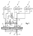
- Fig. 1 shows a schematic representation of a Hydraulic diagram, as it is for one of the state of the art known three-point device construction is conceivable.
- Upper link a two-sided acting length adjustable Hydraulic unit 10, which in concrete each in the form of a two-sided acting hydraulic cylinder is executed.
- lower links are each with the hydraulic units 12 and 14 raised or lowered, with In other words, with the hydraulic units 12 and 14 in changed their orientation.
- the two hydraulic units 12, 14 are in the form of two-sided acting length-adjustable hydraulic cylinders formed. Same or similar components or assemblies are in the Fig. With each identified the same reference numerals.
- All of the hydraulic units 10, 12, 14 shown in FIG. 1 can over there provided supply lines 20 with a Hydraulic supply 16 and a hydraulic tank 18 is connected are provided, provided the two valves 22, 24 are located in a corresponding valve position.
- Both Supply lines 20 are in the concrete order Hydraulic lines for transporting or receiving Hydraulic fluid.
- the valves 22, 24 are in concrete terms, proportional valves. In that shown in Fig. 1 Currently active valve position of the valves 22, 24 are the Hydraulic units 10, 12 and 14 each of the Hydraulic supply 16 and the hydraulic tank 18 is disconnected.
- the double-acting hydraulic cylinder of the Hydraulic units 10, 12, 14 each include a piston chamber 26, 28, 30 and a piston rod chamber 32, 34, 36.
- connection lines 38 are provided, with which the Connecting lines 20, which from the valve 22 to the Hydraulic unit 10 extend, with the connecting lines 20th are connectable, which between the valve 24 and the Hydraulic units 12, 14 extend.
- the connection lines 38 have another valve 40, with which the Connecting lines 38 are interruptible.
- About the Shut-off valve 42 are the piston chambers 28, 30 of the Hydraulic units 12, 14 connected to the hydraulic tank 18.
- valve is in the form of a 4/4-way valve 22 with its left valve position in the active position is, the piston of the hydraulic unit 10 or extended the top link of the three-point device structure.
- the hydraulic unit 10 In the in Fig. 1 position of the valve 22, in the second Valve position from the left, the hydraulic unit 10 remains in their position, provided that the further valve 40 itself is in the position shown in FIG. 1. If that Valve 22 contacts the third valve position from the left in the active position is assigned to the top link Retracted hydraulic unit 10. If the valve 22 with the right valve position is in the active position, is both the piston chamber 26 and the piston rod chamber 32nd the hydraulic unit 10 connected to the hydraulic tank 18, with in other words, depressurized. The same applies for the valve positions of the valve 24, with which the Hydraulic units 12, 14 are controlled accordingly, as the Supply lines 20 between the valve 24 and the Hydraulic units 12, 14 are interconnected.
- Figs. 2 to 7 show an embodiment of a Hydraulic circuit diagram according to the invention, with which the Hydraulic units 10, 12 and 14 can be controlled.
- the valve 22 the Control of the hydraulic unit 12 is the valve 24 and the Control of the hydraulic unit 14 is the valve 44 intended. Accordingly, therefore, the hydraulic unit 12th independent of the hydraulic unit 14 via the two valves 24, 44 are controlled. This can be done with the help of Connecting lines 38, the corresponding supply lines 20 of the hydraulic units 12, 14 are connected, which between the valve 24 and the hydraulic unit 12 and run between the valve 44 and the hydraulic unit 14.
- 44, 40 are all hydraulic units 10, 12, 14 in one rigid position, so that a working device attached to a Work vehicle is coupled, no relative movements to Work vehicle can perform.
- both valves 40 are on Passage switched, so that the piston chamber 26 of the Hydraulic unit 10 with the piston rod chambers 34, 36 of the Hydraulic units 12, 14 are connected.
- This can be a on the upper link and thus on the hydraulic unit 10th acting compressive force in a Hubkraftkomponente on the Hydraulic units 12, 14 are transmitted.
- the on the Hydraulic unit 10 acting force is essentially from the implement weight and the traction of the Working device together. It is with such an interconnection possible to transfer a weight of a working device to the To realize work vehicle, which depends on the Implement weight and the required traction is.
- Weight transfer refers to the burden of Front axle of the working vehicle depending on the on the Work vehicle acting support load of the implement.
- valve position of FIG. 3 Especially advantageous in the valve position of FIG. 3 is that the hydraulic units 10, 12, 14 a "kinking" of the implement relative to the work vehicle around the Support working vehicle transverse axis. This can do that Work tool better from the movements of the work vehicle be decoupled.
- This circuit is especially for Equipment suitable, which are guided on a roller. In the circuit shown in Fig. 3 is dependent on the vertical load of the implement, which is a corresponding hydraulic pressure in the piston rod spaces 34, 36 of the Hydraulic units 12, 14 corresponds to the hydraulic unit 10th burdened, whereby the weight transfer of the relevant Support load achieved on the front axle of the work vehicle becomes.
- a working vehicle with a high Traction requirement at low weight and lower Einziehskraft is uncouple, is preferably provided, the Adjust valves 22, 24, 44, 40 and 42, as in Fig. 5 is shown. Again, the top link or the Hydraulic unit 10 locked so that a traction between implement and commercial vehicle only over one Parallelogram is realized, which of the upper link and the lower links is stretched. The work tool can become even through a roller lead into the depth or through the Lower the height of the lower link of the work vehicle.
- the hydraulic units 12, 14 are interconnected to a better ground adaptation of the implement to the Vehicle longitudinal axis to ensure.
- the circuit of FIG. 5 has the advantage that work tools, due to their Vertical component of traction not keep its working depth can, their working depth with the invention Can hold device without additional device weight, such as which could be the case with underground hoes, for example.
- the three-point device construction according to the invention also be used to towed implements to the Couple commercial vehicle.
- This can be additional Degrees of freedom around the vehicle transverse axis - and at a Design of the three-point device structure without lift shaft - also around the vehicle longitudinal axis can be used.
- circuits namely a) a control without weight transfer between work vehicle and Working device, b) a control with weight transfer to the Front axle of the working vehicle and c) a control with negative vertical load.
- An activation to b) is for example Fig. 3 removable.
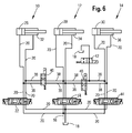
- a control to a) Fig. 6 can be removed.
- the piston chambers 28, 30 are over the Valve 42 is connected to the hydraulic tank 18.
- the degree of freedom of Movements between work vehicle and implement around the Vehicle transverse axis is by the hydraulic unit 10th realized, which is in floating position. hereby a vibration damping for towed equipment is possible.
- a control to c) Fig. 7 can be removed, which for Implements with negative support load is suitable. Neg Support loads can be particularly at empty or unequal laden implements arise.
- the hydraulic unit 10 is also in floating position and does not take any Forces up.
- the interconnected hydraulic units 12, 14 take the vertical load of the implement, the pressure now in the piston chambers 28, 30 of the hydraulic units 12, 14 prevails.
- the interconnected piston rod spaces 34, 36 of the hydraulic units 12, 14 absorb no forces and are therefore depressurized. Also in this control of Hydraulic units 10, 12, 14 are degrees of freedom and the Vehicle transverse axis and the vehicle's longitudinal axis possible.
Landscapes
- Life Sciences & Earth Sciences (AREA)
- Engineering & Computer Science (AREA)
- Mechanical Engineering (AREA)
- Soil Sciences (AREA)
- Environmental Sciences (AREA)
- Fluid-Pressure Circuits (AREA)
Abstract
Description
- Fig. 1
- einen Schaltplan für einen konventionellen Dreipunkt-Geräteaufbau, wie er aus dem Stand der Technik bekannt ist,
- Fig. 2
- ein Ausführungsbeispiel eines Schaltplans einer erfindungsgemäßen Vorrichtung zur Ansteuerung eines Dreipunkt-Geräteaufbaus für ein landwirtschaftliches oder industrielles Nutzfahrzeug,
- Fig. 3 bis 7
- jeweils den Schaltplan aus Fig. 2, bei welchem jeweils eine andere Ventilstellung vorliegt.
Claims (21)
- Vorrichtung zur Ansteuerung eines Dreipunkt-Geräteaufbaus für ein landwirtschaftliches oder industrielles Nutzfahrzeug, insbesondere für einen Traktor, wobei der Dreipunkt-Geräteaufbau einen Oberlenker und zwei Unterlenker umfasst, wobei zur Verstellung der Ausrichtung eines Unterlenkers eine zweiseitig wirkende längenverstellbare Hydraulikeinheit (12, 14) vorgesehen ist, wobei eine Hydraulikeinheit (12, 14) jeweils über mindestens eine Versorgungsleitung (20) mit einer Hydraulikversorgung (16) und/oder mit einem Hydrauliktank (18) verbindbar ist, und wobei die Versorgungsleitungen (20) derart ausgebildet sind, dass die Hydraulikeinheiten (12, 14) jeweils unabhängig voneinander ansteuerbar sind, dadurch gekennzeichnet, dass die Versorgungsleitungen (20) derart ausgebildet sind, dass die die Unterlenker betreffenden Hydraulikeinheiten (12, 14) auch dann miteinander verbindbar sind, wenn die Hydraulikeinheiten (12, 14) nicht mit der Hydraulikversorgung (16) und/oder mit dem Hydrauliktank (18) verbunden sind.
- Vorrichtung nach Anspruch 1, dadurch gekennzeichnet, dass der Oberlenker eine zweiseitig wirkende längenverstellbare Hydraulikeinheit (10) aufweist.
- Vorrichtung nach Anspruch 1 oder 2, dadurch gekennzeichnet, dass eine Hydraulikeinheit (10, 12, 14) mindestens einen Hydraulikzylinder aufweist, welcher vorzugsweise einen Kolbenraum (26, 28, 30) und einen Kolbenstangenraum (32, 34, 36) aufweist, wobei insbesondere sowohl der Kolbenraum (26, 28, 30) als auch der Kolbenstangenraum (32, 34, 36) jeweils an eine Versorgungsleitung (20) anschließbar ist.
- Vorrichtung nach einem der Ansprüche 1 bis 3, dadurch gekennzeichnet, dass der Teil der Versorgungsleitung (20) zwischen der Hydraulikversorgung (16) oder dem Hydrauliktank (18) und einer Hydraulikeinheit (10, 12, 14) mindestens ein Ventil (22, 24, 44) aufweist, welches vorzugsweise in Form eines Mehrwegventils, insbesondere als 4/4-Wegventil ausgebildet ist, und welches in Form eines Proportionalventils ausgebildet sein kann.
- Vorrichtung nach Anspruch 4, dadurch gekennzeichnet, dass ein Ventil (22, 24, 44) derart ausgebildet und ansteuerbar ist, dass die Verbindung zwischen dem Kolbenraum (26, 28, 30) einer Hydraulikeinheit (10, 12, 14) und der Hydraulikversorgung (16) oder dem Hydrauliktank (18) herstellbar oder unterbrechbar ist.
- Vorrichtung nach Anspruch 4 oder 5, dadurch gekennzeichnet, dass ein Ventil (22, 24, 44) derart ausgebildet und ansteuerbar ist, dass die Verbindung zwischen dem Kolbenstangenraum (32, 34, 36) einer Hydraulikeinheit (10, 12, 14) und der Hydraulikversorgung (16) oder dem Hydrauliktank (8) herstellbar oder unterbrechbar ist.
- Vorrichtung nach einem der Ansprüche 1 bis 6, dadurch gekennzeichnet, dass die Versorgungsleitungen (20), welche zwischen einem Ventil (24) und einer dem Ventil (24) zugeordneten Hydraulikeinheit (12) angeordnet sind, mit den Versorgungsleitungen (20), welche zwischen einem anderen Ventil (44) und einer dem anderen Ventil (44) zugeordneten anderen Hydraulikeinheit (14) angeordnet sind, über Verbindungsleitungen (38) miteinander verbindbar und/oder unterbrechbar sind.
- Vorrichtung nach Anspruch 7, dadurch gekennzeichnet, dass eine Verbindungsleitung (38) ein weiteres Ventil (40) aufweist, mit welchem die Verbindung unterschiedlicher Hydraulikeinheiten (12, 14) miteinander verbindbar und/oder unterbrechbar ist.
- Vorrichtung nach Anspruch 8, dadurch gekennzeichnet, dass das weitere Ventil (40) in Form eines 4/2-Wegventils ausgebildet ist, mit welchem vorzugsweise der Kolbenraum (28, 30) und der Kolbenstangenraum (34, 36) unterschiedlicher Hydraulikeinheiten (12, 14) miteinander verbindbar und/oder unterbrechbar sind.
- Vorrichtung nach einem der Ansprüche 6 bis 9, dadurch gekennzeichnet, dass mindestens eine Verbindungsleitung (38) - vorzugsweise mittels eines Absperrventils (42) - mit dem Hydrauliktank (18) verbindbar ist.
- Verfahren zur Ansteuerung eines Dreipunkt-Geräteaufbaus für ein landwirtschaftliches oder industrielles Nutzfahrzeug, insbesondere für einen Traktor, wobei der Dreipunkt-Geräteaufbau einen Oberlenker und zwei Unterlenker umfasst, wobei die Ausrichtung eines Unterlenkers mit einer zweiseitig wirkenden längenverstellbaren Hydraulikeinheit (12, 14) erfolgt, wobei eine Hydraulikeinheit (12, 14) jeweils über mindestens eine Versorgungsleitung (20) mit einer Hydraulikversorgung (16) und/oder mit einem Hydrauliktank (18) verbunden werden kann und wobei die Versorgungsleitungen (20) derart ausgebildet sind, dass zumindest in einem Betriebsmodus die Hydraulikeinheiten (12, 14) jeweils unabhängig voneinander angesteuert werden, vorzugsweise zur Ansteuerung einer Vorrichtung nach einem der Ansprüche 1 bis 10, dadurch gekennzeichnet, dass die Versorgungsleitungen (20) derart ausgebildet sind, dass zumindest in einem Betriebsmodus die die Unterlenker betreffende Hydraulikeinheiten (12, 14) auch dann miteinander verbunden werden, wenn die Hydraulikeinheiten (12, 14) nicht mit der Hydraulikversorgung (16) und/oder mit dem Hydrauliktank (18) verbunden sind.
- Verfahren nach Anspruch 11, dadurch gekennzeichnet, dass der Oberlenker eine zweiseitig wirkende längenverstellbare Hydraulikeinheit (10) aufweist.
- Verfahren nach Anspruch 11 oder 12, dadurch gekennzeichnet, dass eine Hydraulikeinheit (10, 12, 14) mindestens einen Hydraulikzylinder aufweist, welcher vorzugsweise einen Kolbenraum (26, 28, 30) und einen Kolbenstangenraum (32, 34, 36) aufweist, wobei sowohl der Kolbenraum (26, 28, 30) als auch der Kolbenstangenraum (32, 34, 36) jeweils an eine Versorgungsleitung (20) angeschlossen werden kann.
- Verfahren nach Anspruch 13, dadurch gekennzeichnet, dass der Kolbenraum (26, 28, 30) und/oder der Kolbenstangenraum (32, 34, 36) sämtlicher Hydraulikeinheiten (10, 12, 14) von der Hydraulikversorgung (16) und von dem Hydrauliktank (18) getrennt werden.
- Verfahren nach Anspruch 13 oder 14, dadurch gekennzeichnet, dass der Kolbenraum (28, 30) und/oder der Kolbenstangenraum (34, 36) mindestens zweier Hydraulikeinheiten (12, 14) voneinander getrennt werden.
- Verfahren nach einem der Ansprüche 13 bis 15, dadurch gekennzeichnet, dass der Kolbenraum (26, 28, 30) und/oder der Kolbenstangenraum (32, 34, 36) mindestens zweier Hydraulikeinheiten (10, 12, 14) miteinander verbunden werden.
- Verfahren nach einem der Ansprüche 11 bis 16, dadurch gekennzeichnet, dass der Teil der Versorgungsleitung (20) zwischen der Hydraulikversorgung (16) oder dem Hydrauliktank (18) und einer Hydraulikeinheit (10, 12, 14) mindestens ein Ventil (22, 24, 44) aufweist, welches vorzugsweise in Form eines Mehrwegventils, insbesondere als 4/4-Wegventil ausgebildet ist, und welches in Form eines Proportionalventils ausgebildet sein kann.
- Verfahren nach Anspruch 17, dadurch gekennzeichnet, dass die Verbindung zweier Hydraulikzylinder (12, 14) mittels Verbindungsleitungen (38) hergestellt und/oder unterbrochen wird, wobei die Verbindungsleitungen (38) die Versorgungsleitungen (20), welche zwischen einem Ventil (24) und einer dem Ventil (24) zugeordneten Hydraulikeinheit (12) angeordnet sind, mit den Versorgungsleitungen (20), welche zwischen einem anderen Ventil (44) und einer dem anderen Ventil (44) zugeordneten anderen Hydraulikeinheit (14) angeordnet sind, miteinander verbinden.
- Verfahren nach einem der Ansprüche 13 bis 18, dadurch gekennzeichnet, dass der Kolbenraum (26, 28, 30) und/oder der Kolbenstangenraum (32, 34, 36) mindestens einer Hydraulikeinheit (10, 12, 14) mit dem Hydrauliktank (16) verbunden wird.
- Verfahren nach einem der Ansprüche 13 bis 19, dadurch gekennzeichnet, dass die Kolbenräume (28, 30) beider zur Verstellung der Ausrichtung der Unterlenker vorgesehenen Hydraulikeinheiten (12, 14) mit dem Hydrauliktank (18) verbunden werden.
- Verfahren nach einem der Ansprüche 13 bis 20, dadurch gekennzeichnet, dass die Kolbenräume (26, 28, 30) sämtlicher Hydraulikeinheiten (10, 12, 14) mit dem Hydrauliktank (18) verbunden werden.
Priority Applications (1)
| Application Number | Priority Date | Filing Date | Title |
|---|---|---|---|
| EP04102014.0A EP1477052B1 (de) | 2003-05-12 | 2004-05-10 | Vorrichtung und Verfahren zur Ansteuerung eines Dreipunkt-Geräteaufbaus |
Applications Claiming Priority (5)
| Application Number | Priority Date | Filing Date | Title |
|---|---|---|---|
| WOPCT/EP03/04955 | 2003-05-12 | ||
| PCT/EP2003/004955 WO2003094591A1 (de) | 2002-05-11 | 2003-05-12 | Vorrichtung zur kopplung zweier einheiten aneinander |
| DE10352898 | 2003-11-11 | ||
| DE10352898A DE10352898A1 (de) | 2003-05-12 | 2003-11-11 | Vorrichtung und Verfahren zur Ansteuerung eines Dreipunkt-Geräteaufbaus |
| EP04102014.0A EP1477052B1 (de) | 2003-05-12 | 2004-05-10 | Vorrichtung und Verfahren zur Ansteuerung eines Dreipunkt-Geräteaufbaus |
Publications (2)
| Publication Number | Publication Date |
|---|---|
| EP1477052A1 true EP1477052A1 (de) | 2004-11-17 |
| EP1477052B1 EP1477052B1 (de) | 2013-08-21 |
Family
ID=34530223
Family Applications (1)
| Application Number | Title | Priority Date | Filing Date |
|---|---|---|---|
| EP04102014.0A Expired - Lifetime EP1477052B1 (de) | 2003-05-12 | 2004-05-10 | Vorrichtung und Verfahren zur Ansteuerung eines Dreipunkt-Geräteaufbaus |
Country Status (3)
| Country | Link |
|---|---|
| US (1) | US6971453B2 (de) |
| EP (1) | EP1477052B1 (de) |
| DE (1) | DE10352898A1 (de) |
Cited By (1)
| Publication number | Priority date | Publication date | Assignee | Title |
|---|---|---|---|---|
| DE102022111489A1 (de) | 2022-05-09 | 2023-11-09 | Weber-Hydraulik Gmbh | Hydraulische Verstellvorrichtung |
Families Citing this family (10)
| Publication number | Priority date | Publication date | Assignee | Title |
|---|---|---|---|---|
| DE10342403A1 (de) * | 2003-09-13 | 2005-04-07 | Deere & Company, Moline | Vorrichtung zur Kopplung eines Arbeitsgeräts an ein Arbeitsfahrzeug |
| GB0723993D0 (en) * | 2007-12-08 | 2008-01-16 | Agco Sa | Implement control system |
| DE102010019819B4 (de) * | 2010-05-08 | 2014-09-18 | Lemken Gmbh & Co. Kg | Aufsatteldrehpflug |
| DE102011120302A1 (de) | 2011-12-03 | 2013-06-06 | Robert Bosch Gmbh | Hydraulisches Wegeventil für das Hubwerk eines landwirtschaftlichen Fahrzeugs |
| DE102013207299B4 (de) | 2013-04-23 | 2025-11-06 | Robert Bosch Gmbh | Hydraulisches Wegeventil für das Hubwerk eines landwirtschaftlichen Fahrzeugs |
| US12133481B2 (en) * | 2017-12-14 | 2024-11-05 | Deere & Company | Stabilizer control for an agricultural implement |
| JP7274997B2 (ja) * | 2019-10-01 | 2023-05-17 | 株式会社クボタ | 作業機の油圧システム |
| DE102019216733A1 (de) * | 2019-10-30 | 2021-05-06 | Deere & Company | Dreipunkt-Kraftheber für einen landwirtschaftlichen Traktor |
| US12427817B2 (en) * | 2022-11-29 | 2025-09-30 | Cnh Industrial America Llc | Vehicle with adjustable hitch |
| CN121162636B (zh) * | 2025-11-20 | 2026-02-10 | 第一拖拉机股份有限公司 | 一种用于拖拉机后置三点悬挂装置的多维度减震液压系统 |
Citations (6)
| Publication number | Priority date | Publication date | Assignee | Title |
|---|---|---|---|---|
| FR1270600A (fr) * | 1960-07-19 | 1961-09-01 | Renault | Commande hydraulique à affichage, notamment pour dispositif de relevage hydrauliquede tracteur agricole |
| US3750757A (en) * | 1971-05-27 | 1973-08-07 | Fiat Spa | Control devices for agricultural tractor implements |
| DE19611626A1 (de) * | 1996-03-25 | 1997-11-20 | Berend Schoemaker | Hydraulische Schleppersteuerung |
| US20020195258A1 (en) * | 2001-05-28 | 2002-12-26 | Herbert Coenen | Hydraulic lift device for an attaching device |
| DE19939967C2 (de) | 1999-01-09 | 2003-10-23 | Walterscheid Gmbh Gkn | Hubwerk für Unterlenker einer Anbaueinrichtung eines Traktors |
| US20040079224A1 (en) * | 2002-10-09 | 2004-04-29 | Gerd Bernhardt | Implement attachment interface for the coupling of operating implements to a utility vehicle and valve arrangement |
Family Cites Families (9)
| Publication number | Priority date | Publication date | Assignee | Title |
|---|---|---|---|---|
| US3247910A (en) * | 1963-01-24 | 1966-04-26 | Massey Ferguson Inc | Dual hydraulic lift arrangement with lateral flexibility |
| US4821806A (en) * | 1986-09-05 | 1989-04-18 | Deere & Company | Implement having parallel cylinder depth control and series cylinder lift |
| US5335499A (en) * | 1992-09-24 | 1994-08-09 | Viking Engineering & Development, Incorporated | Multiple hydraulic actuators with series/parallel operation |
| US5449042A (en) * | 1994-05-04 | 1995-09-12 | Deere & Company | Rephasing controlling/controlled hydraulic cylinders in folding implement frame |
| EP1018292B8 (de) * | 1999-01-09 | 2005-06-29 | GKN Walterscheid GmbH | Hubwerk für die Unterlenker einer Anbauvorrichtung eines Traktors |
| DE10000846A1 (de) * | 2000-01-12 | 2001-07-19 | Cramer Kupplung Gmbh & Co Kg | Dreipunktaufhängung für einen Traktor, Schlepper oder dergleichen |
| DE10114092A1 (de) * | 2001-03-22 | 2002-09-26 | Deere & Co | Geräteschnittstelle zwischen Arbeitsfahrzeug und Gerät |
| US6698523B2 (en) * | 2002-07-02 | 2004-03-02 | Husco International, Inc. | Electrohydraulic control system for implement lift cylinders |
| ITBO20020612A1 (it) * | 2002-09-27 | 2004-03-28 | Cnh Italia Spa | Dispositivo di attacco di attrezzi agricoli ad un trattore. |
-
2003
- 2003-11-11 DE DE10352898A patent/DE10352898A1/de not_active Withdrawn
-
2004
- 2004-04-29 US US10/835,314 patent/US6971453B2/en not_active Expired - Lifetime
- 2004-05-10 EP EP04102014.0A patent/EP1477052B1/de not_active Expired - Lifetime
Patent Citations (6)
| Publication number | Priority date | Publication date | Assignee | Title |
|---|---|---|---|---|
| FR1270600A (fr) * | 1960-07-19 | 1961-09-01 | Renault | Commande hydraulique à affichage, notamment pour dispositif de relevage hydrauliquede tracteur agricole |
| US3750757A (en) * | 1971-05-27 | 1973-08-07 | Fiat Spa | Control devices for agricultural tractor implements |
| DE19611626A1 (de) * | 1996-03-25 | 1997-11-20 | Berend Schoemaker | Hydraulische Schleppersteuerung |
| DE19939967C2 (de) | 1999-01-09 | 2003-10-23 | Walterscheid Gmbh Gkn | Hubwerk für Unterlenker einer Anbaueinrichtung eines Traktors |
| US20020195258A1 (en) * | 2001-05-28 | 2002-12-26 | Herbert Coenen | Hydraulic lift device for an attaching device |
| US20040079224A1 (en) * | 2002-10-09 | 2004-04-29 | Gerd Bernhardt | Implement attachment interface for the coupling of operating implements to a utility vehicle and valve arrangement |
Cited By (1)
| Publication number | Priority date | Publication date | Assignee | Title |
|---|---|---|---|---|
| DE102022111489A1 (de) | 2022-05-09 | 2023-11-09 | Weber-Hydraulik Gmbh | Hydraulische Verstellvorrichtung |
Also Published As
| Publication number | Publication date |
|---|---|
| DE10352898A1 (de) | 2004-12-16 |
| US6971453B2 (en) | 2005-12-06 |
| US20050098329A1 (en) | 2005-05-12 |
| EP1477052B1 (de) | 2013-08-21 |
Similar Documents
| Publication | Publication Date | Title |
|---|---|---|
| EP1514463B1 (de) | Vorrichtung zur Kopplung eines Arbeitsgeräts an ein Arbeitsfahrzeug | |
| DE19951840A1 (de) | Anbauschnittstelle zur Kopplung von Arbeitsgeräten an ein Arbeitsfahrzeug | |
| EP1008284A2 (de) | Teleskopierbarer Geräteanbau eines Kraftfahrzeugs | |
| EP1477052B1 (de) | Vorrichtung und Verfahren zur Ansteuerung eines Dreipunkt-Geräteaufbaus | |
| EP1505863A1 (de) | Vorrichtung zur kopplung zweier einheiten aneinander | |
| WO2006111505A1 (de) | Dreipunkt-geräteanbau für ein landwirtschaftliches oder industrielles nutzfahrzeug | |
| DE2262922C2 (de) | Schlepper mit einer Dreipunkthebevorrichtung für ein Bodenbearbeitungsgerät | |
| DE10126029B4 (de) | Hydraulisches Hubwerk für eine Anbaueinrichtung | |
| EP1068780A1 (de) | Verschwenkbarer Geräteanbau eines Kraftfahrzeugs | |
| EP1199194A2 (de) | Vorrichtung zum Kuppeln eines Fahrzeugs mit einem Gerät oder Anhänger | |
| DE202009014618U1 (de) | Tastradfahrwerk für landwirtschaftliches Gerät | |
| DE1109933B (de) | Anbauvorrichtung zum Ankuppeln von Anbaugeraeten an mit einem Kraftheber ausgeruestete Ackerschlepper | |
| DE1455578C3 (de) | Steuervorrichtung für Ackerschlepper mit einem Dreipunktgestänge sowie einem hydraulischen Kraftheber | |
| DE19737318C2 (de) | Vorrichtung zur automatischen Stabilisierung von zwei Unterlenkern einer Geräteanbaueinrichtung an einem landwirtschaftlichen oder forstwirtschaftlichen Schlepper | |
| EP1243170B1 (de) | Geräteschnittstelle zwischen Arbeitsfahrzeug und Gerät | |
| EP0875132B1 (de) | Klapprahmen | |
| EP0068381A1 (de) | Von einem Ackerschlepper nachgeschleppter Pflug | |
| DE10120733A1 (de) | Anbauvorrichtung zur Kopplung eines Arbeitsgerätes an ein Arbeitsfahrzeug | |
| DE10213993C1 (de) | Bodenbearbeitungsgerät mit Stabilisierungseinrichtung | |
| DE9320343U1 (de) | Zur Anordnung an einem Arbeitsfahrzeug vorgesehenes Arbeitsgerät | |
| EP2520146A1 (de) | Gezogenes landwirtschaftliches Gerät | |
| AT221134B (de) | Schneepflug | |
| EP3311640A1 (de) | Anhängevorrichtung für ein landwirtschaftliches zugfahrzeug und ein verfahren zu deren betrieb | |
| AT9794U1 (de) | Landmaschine | |
| DE2539702C2 (de) | u.dgl. bei Kraftfahrzeugen |
Legal Events
| Date | Code | Title | Description |
|---|---|---|---|
| PUAI | Public reference made under article 153(3) epc to a published international application that has entered the european phase |
Free format text: ORIGINAL CODE: 0009012 |
|
| AK | Designated contracting states |
Kind code of ref document: A1 Designated state(s): AT BE BG CH CY CZ DE DK EE ES FI FR GB GR HU IE IT LI LU MC NL PL PT RO SE SI SK TR |
|
| AX | Request for extension of the european patent |
Extension state: AL HR LT LV MK |
|
| 17P | Request for examination filed |
Effective date: 20050517 |
|
| AKX | Designation fees paid |
Designated state(s): AT BE BG CH CY CZ DE DK EE ES FI FR GB GR HU IE IT LI LU MC NL PL PT RO SE SI SK TR |
|
| 17Q | First examination report despatched |
Effective date: 20110504 |
|
| GRAP | Despatch of communication of intention to grant a patent |
Free format text: ORIGINAL CODE: EPIDOSNIGR1 |
|
| INTG | Intention to grant announced |
Effective date: 20130502 |
|
| GRAS | Grant fee paid |
Free format text: ORIGINAL CODE: EPIDOSNIGR3 |
|
| GRAA | (expected) grant |
Free format text: ORIGINAL CODE: 0009210 |
|
| AK | Designated contracting states |
Kind code of ref document: B1 Designated state(s): AT BE BG CH CY CZ DE DK EE ES FI FR GB GR HU IE IT LI LU MC NL PL PT RO SE SI SK TR |
|
| REG | Reference to a national code |
Ref country code: GB Ref legal event code: FG4D Free format text: NOT ENGLISH |
|
| REG | Reference to a national code |
Ref country code: CH Ref legal event code: EP |
|
| REG | Reference to a national code |
Ref country code: AT Ref legal event code: REF Ref document number: 627481 Country of ref document: AT Kind code of ref document: T Effective date: 20130915 |
|
| REG | Reference to a national code |
Ref country code: IE Ref legal event code: FG4D Free format text: LANGUAGE OF EP DOCUMENT: GERMAN |
|
| REG | Reference to a national code |
Ref country code: DE Ref legal event code: R096 Ref document number: 502004014315 Country of ref document: DE Effective date: 20131010 |
|
| REG | Reference to a national code |
Ref country code: NL Ref legal event code: VDEP Effective date: 20130821 |
|
| PG25 | Lapsed in a contracting state [announced via postgrant information from national office to epo] |
Ref country code: SE Free format text: LAPSE BECAUSE OF FAILURE TO SUBMIT A TRANSLATION OF THE DESCRIPTION OR TO PAY THE FEE WITHIN THE PRESCRIBED TIME-LIMIT Effective date: 20130821 Ref country code: CY Free format text: LAPSE BECAUSE OF FAILURE TO SUBMIT A TRANSLATION OF THE DESCRIPTION OR TO PAY THE FEE WITHIN THE PRESCRIBED TIME-LIMIT Effective date: 20130703 Ref country code: PT Free format text: LAPSE BECAUSE OF FAILURE TO SUBMIT A TRANSLATION OF THE DESCRIPTION OR TO PAY THE FEE WITHIN THE PRESCRIBED TIME-LIMIT Effective date: 20131223 |
|
| PG25 | Lapsed in a contracting state [announced via postgrant information from national office to epo] |
Ref country code: SI Free format text: LAPSE BECAUSE OF FAILURE TO SUBMIT A TRANSLATION OF THE DESCRIPTION OR TO PAY THE FEE WITHIN THE PRESCRIBED TIME-LIMIT Effective date: 20130821 Ref country code: GR Free format text: LAPSE BECAUSE OF FAILURE TO SUBMIT A TRANSLATION OF THE DESCRIPTION OR TO PAY THE FEE WITHIN THE PRESCRIBED TIME-LIMIT Effective date: 20131122 Ref country code: PL Free format text: LAPSE BECAUSE OF FAILURE TO SUBMIT A TRANSLATION OF THE DESCRIPTION OR TO PAY THE FEE WITHIN THE PRESCRIBED TIME-LIMIT Effective date: 20130821 |
|
| PG25 | Lapsed in a contracting state [announced via postgrant information from national office to epo] |
Ref country code: CY Free format text: LAPSE BECAUSE OF FAILURE TO SUBMIT A TRANSLATION OF THE DESCRIPTION OR TO PAY THE FEE WITHIN THE PRESCRIBED TIME-LIMIT Effective date: 20130821 |
|
| PG25 | Lapsed in a contracting state [announced via postgrant information from national office to epo] |
Ref country code: EE Free format text: LAPSE BECAUSE OF FAILURE TO SUBMIT A TRANSLATION OF THE DESCRIPTION OR TO PAY THE FEE WITHIN THE PRESCRIBED TIME-LIMIT Effective date: 20130821 Ref country code: RO Free format text: LAPSE BECAUSE OF FAILURE TO SUBMIT A TRANSLATION OF THE DESCRIPTION OR TO PAY THE FEE WITHIN THE PRESCRIBED TIME-LIMIT Effective date: 20130821 Ref country code: CZ Free format text: LAPSE BECAUSE OF FAILURE TO SUBMIT A TRANSLATION OF THE DESCRIPTION OR TO PAY THE FEE WITHIN THE PRESCRIBED TIME-LIMIT Effective date: 20130821 Ref country code: SK Free format text: LAPSE BECAUSE OF FAILURE TO SUBMIT A TRANSLATION OF THE DESCRIPTION OR TO PAY THE FEE WITHIN THE PRESCRIBED TIME-LIMIT Effective date: 20130821 Ref country code: NL Free format text: LAPSE BECAUSE OF FAILURE TO SUBMIT A TRANSLATION OF THE DESCRIPTION OR TO PAY THE FEE WITHIN THE PRESCRIBED TIME-LIMIT Effective date: 20130821 Ref country code: DK Free format text: LAPSE BECAUSE OF FAILURE TO SUBMIT A TRANSLATION OF THE DESCRIPTION OR TO PAY THE FEE WITHIN THE PRESCRIBED TIME-LIMIT Effective date: 20130821 |
|
| PG25 | Lapsed in a contracting state [announced via postgrant information from national office to epo] |
Ref country code: ES Free format text: LAPSE BECAUSE OF FAILURE TO SUBMIT A TRANSLATION OF THE DESCRIPTION OR TO PAY THE FEE WITHIN THE PRESCRIBED TIME-LIMIT Effective date: 20130821 Ref country code: IT Free format text: LAPSE BECAUSE OF FAILURE TO SUBMIT A TRANSLATION OF THE DESCRIPTION OR TO PAY THE FEE WITHIN THE PRESCRIBED TIME-LIMIT Effective date: 20130821 |
|
| PLBE | No opposition filed within time limit |
Free format text: ORIGINAL CODE: 0009261 |
|
| STAA | Information on the status of an ep patent application or granted ep patent |
Free format text: STATUS: NO OPPOSITION FILED WITHIN TIME LIMIT |
|
| 26N | No opposition filed |
Effective date: 20140522 |
|
| REG | Reference to a national code |
Ref country code: DE Ref legal event code: R097 Ref document number: 502004014315 Country of ref document: DE Effective date: 20140522 |
|
| PG25 | Lapsed in a contracting state [announced via postgrant information from national office to epo] |
Ref country code: LU Free format text: LAPSE BECAUSE OF FAILURE TO SUBMIT A TRANSLATION OF THE DESCRIPTION OR TO PAY THE FEE WITHIN THE PRESCRIBED TIME-LIMIT Effective date: 20140510 |
|
| REG | Reference to a national code |
Ref country code: CH Ref legal event code: PL |
|
| PG25 | Lapsed in a contracting state [announced via postgrant information from national office to epo] |
Ref country code: LI Free format text: LAPSE BECAUSE OF NON-PAYMENT OF DUE FEES Effective date: 20140531 Ref country code: CH Free format text: LAPSE BECAUSE OF NON-PAYMENT OF DUE FEES Effective date: 20140531 Ref country code: MC Free format text: LAPSE BECAUSE OF FAILURE TO SUBMIT A TRANSLATION OF THE DESCRIPTION OR TO PAY THE FEE WITHIN THE PRESCRIBED TIME-LIMIT Effective date: 20130821 |
|
| REG | Reference to a national code |
Ref country code: IE Ref legal event code: MM4A |
|
| PG25 | Lapsed in a contracting state [announced via postgrant information from national office to epo] |
Ref country code: IE Free format text: LAPSE BECAUSE OF NON-PAYMENT OF DUE FEES Effective date: 20140510 |
|
| REG | Reference to a national code |
Ref country code: AT Ref legal event code: MM01 Ref document number: 627481 Country of ref document: AT Kind code of ref document: T Effective date: 20140510 |
|
| PG25 | Lapsed in a contracting state [announced via postgrant information from national office to epo] |
Ref country code: AT Free format text: LAPSE BECAUSE OF NON-PAYMENT OF DUE FEES Effective date: 20140510 |
|
| REG | Reference to a national code |
Ref country code: FR Ref legal event code: PLFP Year of fee payment: 13 |
|
| PG25 | Lapsed in a contracting state [announced via postgrant information from national office to epo] |
Ref country code: BG Free format text: LAPSE BECAUSE OF FAILURE TO SUBMIT A TRANSLATION OF THE DESCRIPTION OR TO PAY THE FEE WITHIN THE PRESCRIBED TIME-LIMIT Effective date: 20130821 |
|
| PG25 | Lapsed in a contracting state [announced via postgrant information from national office to epo] |
Ref country code: BE Free format text: LAPSE BECAUSE OF FAILURE TO SUBMIT A TRANSLATION OF THE DESCRIPTION OR TO PAY THE FEE WITHIN THE PRESCRIBED TIME-LIMIT Effective date: 20140531 Ref country code: TR Free format text: LAPSE BECAUSE OF FAILURE TO SUBMIT A TRANSLATION OF THE DESCRIPTION OR TO PAY THE FEE WITHIN THE PRESCRIBED TIME-LIMIT Effective date: 20130821 Ref country code: HU Free format text: LAPSE BECAUSE OF FAILURE TO SUBMIT A TRANSLATION OF THE DESCRIPTION OR TO PAY THE FEE WITHIN THE PRESCRIBED TIME-LIMIT; INVALID AB INITIO Effective date: 20040510 |
|
| REG | Reference to a national code |
Ref country code: FR Ref legal event code: PLFP Year of fee payment: 14 |
|
| REG | Reference to a national code |
Ref country code: FR Ref legal event code: PLFP Year of fee payment: 15 |
|
| PGFP | Annual fee paid to national office [announced via postgrant information from national office to epo] |
Ref country code: FR Payment date: 20230525 Year of fee payment: 20 Ref country code: DE Payment date: 20230419 Year of fee payment: 20 |
|
| PGFP | Annual fee paid to national office [announced via postgrant information from national office to epo] |
Ref country code: FI Payment date: 20230525 Year of fee payment: 20 |
|
| PGFP | Annual fee paid to national office [announced via postgrant information from national office to epo] |
Ref country code: GB Payment date: 20230529 Year of fee payment: 20 |
|
| REG | Reference to a national code |
Ref country code: DE Ref legal event code: R071 Ref document number: 502004014315 Country of ref document: DE |
|
| REG | Reference to a national code |
Ref country code: GB Ref legal event code: PE20 Expiry date: 20240509 |
|
| PG25 | Lapsed in a contracting state [announced via postgrant information from national office to epo] |
Ref country code: GB Free format text: LAPSE BECAUSE OF EXPIRATION OF PROTECTION Effective date: 20240509 |
|
| PG25 | Lapsed in a contracting state [announced via postgrant information from national office to epo] |
Ref country code: GB Free format text: LAPSE BECAUSE OF EXPIRATION OF PROTECTION Effective date: 20240509 |