EP1476765B1 - Radio frequency power generation and power measurement - Google Patents
Radio frequency power generation and power measurement Download PDFInfo
- Publication number
- EP1476765B1 EP1476765B1 EP03702775A EP03702775A EP1476765B1 EP 1476765 B1 EP1476765 B1 EP 1476765B1 EP 03702775 A EP03702775 A EP 03702775A EP 03702775 A EP03702775 A EP 03702775A EP 1476765 B1 EP1476765 B1 EP 1476765B1
- Authority
- EP
- European Patent Office
- Prior art keywords
- power
- under test
- unit under
- connector
- link
- Prior art date
- Legal status (The legal status is an assumption and is not a legal conclusion. Google has not performed a legal analysis and makes no representation as to the accuracy of the status listed.)
- Expired - Lifetime
Links
- 238000005259 measurement Methods 0.000 title claims abstract description 15
- 238000010248 power generation Methods 0.000 title claims abstract description 14
- 230000005540 biological transmission Effects 0.000 description 9
- 230000008878 coupling Effects 0.000 description 8
- 238000010168 coupling process Methods 0.000 description 8
- 238000005859 coupling reaction Methods 0.000 description 8
- 238000000034 method Methods 0.000 description 3
- 238000004891 communication Methods 0.000 description 1
- 238000010295 mobile communication Methods 0.000 description 1
Images

Classifications
-
- G—PHYSICS
- G01—MEASURING; TESTING
- G01R—MEASURING ELECTRIC VARIABLES; MEASURING MAGNETIC VARIABLES
- G01R21/00—Arrangements for measuring electric power or power factor
-
- G—PHYSICS
- G01—MEASURING; TESTING
- G01R—MEASURING ELECTRIC VARIABLES; MEASURING MAGNETIC VARIABLES
- G01R31/00—Arrangements for testing electric properties; Arrangements for locating electric faults; Arrangements for electrical testing characterised by what is being tested not provided for elsewhere
- G01R31/28—Testing of electronic circuits, e.g. by signal tracer
- G01R31/2832—Specific tests of electronic circuits not provided for elsewhere
- G01R31/2836—Fault-finding or characterising
- G01R31/2839—Fault-finding or characterising using signal generators, power supplies or circuit analysers
- G01R31/2841—Signal generators
-
- G—PHYSICS
- G01—MEASURING; TESTING
- G01R—MEASURING ELECTRIC VARIABLES; MEASURING MAGNETIC VARIABLES
- G01R31/00—Arrangements for testing electric properties; Arrangements for locating electric faults; Arrangements for electrical testing characterised by what is being tested not provided for elsewhere
- G01R31/28—Testing of electronic circuits, e.g. by signal tracer
-
- G—PHYSICS
- G01—MEASURING; TESTING
- G01R—MEASURING ELECTRIC VARIABLES; MEASURING MAGNETIC VARIABLES
- G01R31/00—Arrangements for testing electric properties; Arrangements for locating electric faults; Arrangements for electrical testing characterised by what is being tested not provided for elsewhere
- G01R31/28—Testing of electronic circuits, e.g. by signal tracer
- G01R31/282—Testing of electronic circuits specially adapted for particular applications not provided for elsewhere
- G01R31/2822—Testing of electronic circuits specially adapted for particular applications not provided for elsewhere of microwave or radiofrequency circuits
Definitions
- This invention relates to the generation and measurement of radio frequency (RF) power.
- Figure 1 shows a known example of this technique.
- equipment for generating known RF power is sometimes used with a remote RF power sensing element, which may be connected to a separate means of power measurement, or may form part of a feedback loop which controls the RF power generation equipment.
- a remote RF power sensing element which may be connected to a separate means of power measurement, or may form part of a feedback loop which controls the RF power generation equipment.
- Such a system provides a signal source whose RF power at a defined point is determined by the accuracy of the remote sensor and the coupling device.
- the advantage is that whilst the full RF power generation equipment may be large, the power sensing element and coupling device can be made small, and connected directly to the unit under test.
- Figure 2 shows a known example of this technique.
- the document US 6 313 644 B1 discloses an apparatus and method measuring voltage standing wave ratio in antenna of base station.
- Radio communication equipment often has either a single RF connector for transmission and reception, or one RF connector for transmission and another for reception.
- RF connector for transmission and reception
- Radio communication equipment When characterising such equipment it is required both to measure the RF power transmitted by the unit under test, and to set the RF power received by the unit under test. It is usual to specify both powers at the RF connector or connectors of the unit under test.
- an RF power generation and measurement system for supplying RF power to, and measuring RF power transmitted by a unit under test via at least one RF connector of the unit, the system comprising, a main part, and a remote part connected to the main part by a link and being connectable to said RF connector of the unit under test, wherein said main part includes RF power generation means for supplying RF power to said unit under test via said link, said remote part and said RF connector, said remote part includes sensor means for sensing RF power received from said unit under test via said RF connector and for sensing RF power indicative of said RF power supplied to the unit under test at said RF connector, and said RF power generation means is controlled in response to an output of said sensor means whereby RF power supplied to the unit under test at said RF connector has a predetermined value.
- Embodiments of the invention enable both measurement of RF power transmitted by the unit under test at the RF connector and setting of the RF power received by the unit under test at the RF connector.
- Those components of the system which need to be near the RF connector or connectors are fitted in a small remote assembly. The majority of the system components are in a larger main assembly, allowing freedom in the location of this part.
- the two parts of the system are connected by a link, preferably a flexible link.
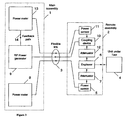
- the system comprises a main assembly part 1 including an RF power generator 9 and power meters 8,13, and a remote assembly part 2 connectable to the RF connector of a unit under test 4 (which may be a mobile communications terminal, for example).
- the main and remote assembly parts are interconnected by a flexible link 3.
- RF power is supplied to, and received from the unit under test by a duplexer 6 in the remote assembly part 2.
- the remote assembly part 2 also includes a first RF power sensor 5 connected to duplexer 2 via an attenuator 7 and a second RF power-sensor 11 connected to an RF coupling device 10, for example a directional coupler or a power splitter, which is also connected to duplexer 6 via a fixed or settable attenuator 12.
- RF power transmitted by the unit under test 4 is measured using the first RF power sensor 5.
- the duplexer 6 directs at least some of the power transmitted by the unit under test 4 to the power sensor 5 via the attenuator 7.
- the attenuator 7 is chosen so that the power sensor 5 receives RF power within its measurement range.
- the duplexer 6, the attenuator 7 and the power sensor 5 are all fitted within the remote assembly 2, to allow them to be connected close to the RF connector of the unit under test 4.
- the electrical output of the power sensor 5 is connected via the flexible link 3 to the power meter 8 fitted within the main assembly part 1. Transmission loss through the duplexer 6 and the attenuator 7 can be characterised, and is used by power meter 8 to give a measurement of RF power transmitted by the unit under test 4 at its RF connector.
- the signal to be received by the unit under test is supplied by the RF power generator 9 in the main assembly part 1. It passes through the flexible link 3, and into the coupling-device 10.
- the coupling device 10 allows a predetermined fraction of the RF power to reach the power sensor 11, and another predetermined fraction to reach the RF connector of the unit under test 4 via the attenuator 12 and the duplexer 6.
- the coupling device 10, the attenuator 12 and the power sensor 11 are all fitted within the remote assembly part 2, to allow them to be connected close to the RF connector of the unit under test 4.
- the electrical output of the power sensor 11 is connected via the flexible link 3 to the power meter 13 fitted within the main assembly part 1.
- the RF transmission characteristics of the coupling device 10, and loss through the attenuator 12 and the duplexer 6 can be characterised and used by power meter 13 to give a measurement of RF power received by the unit under test 4 at its RF connector.
- the value reported by power meter 13 is used to correct the output level of the RF power generator 9 via a feedback path 14.
- the characteristics of the duplexer 6 and the coupling device 10, and the value of the attenuator 12, are chosen so that the power sensor 11 is not significantly affected by the RF power transmitted by the unit under test 4.
- the characteristics of the duplexer 6 and the value of the attenuator 7 are chosen so that the power sensor 5 is not significantly affected by the RF power transmitted by the RF power generator 9.
- the electrical outputs of one or both power sensors 5,11 need not necessarily be supplied to power meters located in the main assembly part 1. Alternatively, these outputs could be supplied to separate metering apparatus remote from the main assembly part 1. In an alternative implementation, a single power sensor means may be used to perform the functions of power sensor 5 and power sensor 11, for example by being switched between the output of attenuator 7 and the coupling device 10.
Landscapes
- Engineering & Computer Science (AREA)
- Physics & Mathematics (AREA)
- General Physics & Mathematics (AREA)
- General Engineering & Computer Science (AREA)
- Power Engineering (AREA)
- Arrangements For Transmission Of Measured Signals (AREA)
- Developing Agents For Electrophotography (AREA)
- Diaphragms For Electromechanical Transducers (AREA)
- Eye Examination Apparatus (AREA)
- Testing Electric Properties And Detecting Electric Faults (AREA)
Applications Claiming Priority (3)
| Application Number | Priority Date | Filing Date | Title |
|---|---|---|---|
| GB0204013A GB2385674B (en) | 2002-02-20 | 2002-02-20 | Radio frequency power generation and power measurement |
| GB0204013 | 2002-02-20 | ||
| PCT/GB2003/000701 WO2003071296A1 (en) | 2002-02-20 | 2003-02-18 | Radio frequency power generation and power measurement |
Publications (2)
| Publication Number | Publication Date |
|---|---|
| EP1476765A1 EP1476765A1 (en) | 2004-11-17 |
| EP1476765B1 true EP1476765B1 (en) | 2006-04-19 |
Family
ID=9931444
Family Applications (1)
| Application Number | Title | Priority Date | Filing Date |
|---|---|---|---|
| EP03702775A Expired - Lifetime EP1476765B1 (en) | 2002-02-20 | 2003-02-18 | Radio frequency power generation and power measurement |
Country Status (10)
| Country | Link |
|---|---|
| US (1) | US7098646B2 (https=) |
| EP (1) | EP1476765B1 (https=) |
| JP (1) | JP2005517964A (https=) |
| KR (1) | KR100794877B1 (https=) |
| AT (1) | ATE323887T1 (https=) |
| AU (1) | AU2003205897A1 (https=) |
| DE (1) | DE60304684T2 (https=) |
| ES (1) | ES2258215T3 (https=) |
| GB (1) | GB2385674B (https=) |
| WO (1) | WO2003071296A1 (https=) |
Families Citing this family (9)
| Publication number | Priority date | Publication date | Assignee | Title |
|---|---|---|---|---|
| US7466240B2 (en) * | 2005-01-25 | 2008-12-16 | The Retents Of The University Of California | Wireless sensing node powered by energy conversion from sensed system |
| US7888947B2 (en) | 2007-11-21 | 2011-02-15 | Teradyne, Inc. | Calibrating automatic test equipment |
| DE102007056268A1 (de) | 2007-11-22 | 2009-05-28 | Rohde & Schwarz Gmbh & Co. Kg | Leistungsmessung mit einem Signalgenerator |
| KR100964974B1 (ko) * | 2007-11-29 | 2010-06-21 | 한국전자통신연구원 | 고주파 디바이스의 대전력 테스트 시스템 및 그의 방법 |
| WO2012129433A2 (en) | 2011-03-22 | 2012-09-27 | The Johns Hopkins University | System and method of performing magnetic resonance spectroscopic imaging |
| WO2012129430A2 (en) * | 2011-03-22 | 2012-09-27 | The Johns Hopkins University | High dynamic range rf power monitor |
| US20130076337A1 (en) * | 2011-09-26 | 2013-03-28 | Dechnia, LLC | Dynamic RF Power Measurement with Visualization |
| US10120049B2 (en) | 2015-05-18 | 2018-11-06 | The Johns Hopkins University | System and method of obtaining spatially-encoded NMR parameters from arbitrarily-shaped compartments and linear algebraic modeling |
| IT201900022140A1 (it) * | 2019-11-26 | 2021-05-26 | Prysmian Spa | Sistema di misurazione di impianti elettrici |
Family Cites Families (13)
| Publication number | Priority date | Publication date | Assignee | Title |
|---|---|---|---|---|
| US4547728A (en) | 1982-08-31 | 1985-10-15 | Bird Electronic Corporation | RF Wattmeter |
| US4758775A (en) * | 1987-04-10 | 1988-07-19 | Eip Microwave, Inc. | Broad band coupler |
| GB8721668D0 (en) * | 1987-09-15 | 1987-10-21 | Secr Defence | Microwave network analyser |
| US4820047A (en) * | 1987-12-22 | 1989-04-11 | Snyder James J | Laser heterodyne apparatus for measuring optical power |
| CA2030272C (en) * | 1989-11-24 | 1995-06-27 | David R. Brunfeldt | Vector network analyzer |
| US5373237A (en) * | 1993-06-02 | 1994-12-13 | Imperato; John | Radio frequency power measurement system |
| US6147481A (en) * | 1996-12-27 | 2000-11-14 | Emc Technology Llc | Termination for RF circuit which senses changes in power and which is not temperature sensitive |
| KR100218152B1 (ko) * | 1997-02-06 | 1999-09-01 | 서평원 | 기지국 안테나의 전압정재파비 측정장치 및 그 방법 |
| GB2347754A (en) * | 1999-03-11 | 2000-09-13 | Alenia Marconi Syst Ltd | Measuring electromagnetic energy device parameters |
| US6268735B1 (en) * | 1999-06-04 | 2001-07-31 | Teradyne, Inc. | Noise source module for microwave test systems |
| US6215448B1 (en) * | 1999-07-30 | 2001-04-10 | Agilent Technologies | Broadband coupler for measurement of antenna signals |
| US6801767B1 (en) * | 2001-01-26 | 2004-10-05 | Lgc Wireless, Inc. | Method and system for distributing multiband wireless communications signals |
| US6859283B2 (en) * | 2002-06-17 | 2005-02-22 | Lightwave Electronics Corporation | Apparatus and method for measuring phase response of optical detectors using multiple-beatnote optical heterodyne |
-
2002
- 2002-02-20 GB GB0204013A patent/GB2385674B/en not_active Expired - Fee Related
-
2003
- 2003-02-18 EP EP03702775A patent/EP1476765B1/en not_active Expired - Lifetime
- 2003-02-18 ES ES03702775T patent/ES2258215T3/es not_active Expired - Lifetime
- 2003-02-18 AT AT03702775T patent/ATE323887T1/de not_active IP Right Cessation
- 2003-02-18 DE DE60304684T patent/DE60304684T2/de not_active Expired - Fee Related
- 2003-02-18 AU AU2003205897A patent/AU2003205897A1/en not_active Abandoned
- 2003-02-18 WO PCT/GB2003/000701 patent/WO2003071296A1/en not_active Ceased
- 2003-02-18 JP JP2003570146A patent/JP2005517964A/ja active Pending
- 2003-02-18 KR KR1020047012842A patent/KR100794877B1/ko not_active Expired - Fee Related
- 2003-02-18 US US10/504,682 patent/US7098646B2/en not_active Expired - Fee Related
Also Published As
| Publication number | Publication date |
|---|---|
| GB2385674A (en) | 2003-08-27 |
| US7098646B2 (en) | 2006-08-29 |
| EP1476765A1 (en) | 2004-11-17 |
| ATE323887T1 (de) | 2006-05-15 |
| KR100794877B1 (ko) | 2008-01-14 |
| GB2385674B (en) | 2005-04-06 |
| GB0204013D0 (en) | 2002-04-03 |
| US20050174234A1 (en) | 2005-08-11 |
| DE60304684T2 (de) | 2006-09-14 |
| WO2003071296A1 (en) | 2003-08-28 |
| KR20040097130A (ko) | 2004-11-17 |
| DE60304684D1 (de) | 2006-05-24 |
| JP2005517964A (ja) | 2005-06-16 |
| AU2003205897A1 (en) | 2003-09-09 |
| ES2258215T3 (es) | 2006-08-16 |
Similar Documents
| Publication | Publication Date | Title |
|---|---|---|
| FI98259C (fi) | Menetelmä ja laitteisto testisilmukan muodostamiseksi radioaseman toiminnan valvontaan | |
| KR100218152B1 (ko) | 기지국 안테나의 전압정재파비 측정장치 및 그 방법 | |
| US9979496B2 (en) | System and method for calibration and monitoring of an anechoic boundary array RF environment simulator | |
| EP1476765B1 (en) | Radio frequency power generation and power measurement | |
| EP0642672B1 (en) | Arrangement for measuring the condition of a receiver antenna | |
| KR20120064686A (ko) | 하이브리드 반사계 시스템(hrs) | |
| JP2005534224A (ja) | 電力増幅器およびアンテナ間の動的インピーダンスマッチング装置 | |
| KR100206463B1 (ko) | 이동체 통신장치의 무선특성 평가 장치 | |
| US6131020A (en) | Arrangement for measuring condition of antenna in mobile telephone system | |
| US6879918B2 (en) | Method and apparatus for measuring the transmission loss of a cable | |
| EP0543835B1 (en) | Method and device for supervising the condition of a receiving antenna | |
| JP2000009776A (ja) | 無線通信特性試験装置 | |
| KR100270647B1 (ko) | 이동통신 시스템의 기지국 송신출력보정장치 및 방법 | |
| KR100523995B1 (ko) | 고주파 스위치 메트릭스를 이용한 고주파 신호 중계기의성능 측정 장치 | |
| JP2000039460A (ja) | 無線装置の評価方法 | |
| KR100563321B1 (ko) | 신호발생기와 신호분석기를 가지는 무선망 관리장치 및그를 이용한 기능 측정방법 | |
| FI80817B (fi) | Anordning foer kontroll av kondition av basstationens antenn vid celltelefonsystem. | |
| KR100462461B1 (ko) | 특정 흡수율 측정 시스템의 유효성 시험용 표준 신호원공급 장치 | |
| KR20010038980A (ko) | 이중 편파 안테나를 채용한 이동통신 시스템내 기지국의 액티브 안테나의 이득 측정장치 | |
| KR100413424B1 (ko) | 기지국 시험장비의 자체 진단 방법 | |
| RU2030752C1 (ru) | Способ определения взаимного сопротивления связанных антенн | |
| KR20030028604A (ko) | Cdma 기지국 송수신 안테나 전압 정재파비 측정 장치및 방법 | |
| KR20060078307A (ko) | 반사되는 무선 신호 레벨 측정을 통해 기지국으로출력되는 무선 신호의 송신전력 제어가 가능한 이동통신단말기 | |
| KR20060071948A (ko) | 이동 통신 단말기의 송신전력 제어장치 | |
| KR20020011545A (ko) | 이동통신시스템의 송수신 신호 경로 자동화 장치 |
Legal Events
| Date | Code | Title | Description |
|---|---|---|---|
| PUAI | Public reference made under article 153(3) epc to a published international application that has entered the european phase |
Free format text: ORIGINAL CODE: 0009012 |
|
| 17P | Request for examination filed |
Effective date: 20040823 |
|
| AK | Designated contracting states |
Kind code of ref document: A1 Designated state(s): AT BE BG CH CY CZ DE DK EE ES FI FR GB GR HU IE IT LI LU MC NL PT SE SI SK TR |
|
| AX | Request for extension of the european patent |
Extension state: AL LT LV MK RO |
|
| GRAP | Despatch of communication of intention to grant a patent |
Free format text: ORIGINAL CODE: EPIDOSNIGR1 |
|
| GRAS | Grant fee paid |
Free format text: ORIGINAL CODE: EPIDOSNIGR3 |
|
| RBV | Designated contracting states (corrected) |
Designated state(s): AT BE BG CH CY CZ DE DK EE ES FI FR GR HU IE IT LI LU MC NL PT SE SI SK TR |
|
| GRAA | (expected) grant |
Free format text: ORIGINAL CODE: 0009210 |
|
| AK | Designated contracting states |
Kind code of ref document: B1 Designated state(s): AT BE BG CH CY CZ DE DK EE ES FI FR GR HU IE IT LI LU MC NL PT SE SI SK TR |
|
| PG25 | Lapsed in a contracting state [announced via postgrant information from national office to epo] |
Ref country code: IT Free format text: LAPSE BECAUSE OF FAILURE TO SUBMIT A TRANSLATION OF THE DESCRIPTION OR TO PAY THE FEE WITHIN THE PRESCRIBED TIME-LIMIT;WARNING: LAPSES OF ITALIAN PATENTS WITH EFFECTIVE DATE BEFORE 2007 MAY HAVE OCCURRED AT ANY TIME BEFORE 2007. THE CORRECT EFFECTIVE DATE MAY BE DIFFERENT FROM THE ONE RECORDED. Effective date: 20060419 Ref country code: CH Free format text: LAPSE BECAUSE OF FAILURE TO SUBMIT A TRANSLATION OF THE DESCRIPTION OR TO PAY THE FEE WITHIN THE PRESCRIBED TIME-LIMIT Effective date: 20060419 Ref country code: AT Free format text: LAPSE BECAUSE OF FAILURE TO SUBMIT A TRANSLATION OF THE DESCRIPTION OR TO PAY THE FEE WITHIN THE PRESCRIBED TIME-LIMIT Effective date: 20060419 Ref country code: CZ Free format text: LAPSE BECAUSE OF FAILURE TO SUBMIT A TRANSLATION OF THE DESCRIPTION OR TO PAY THE FEE WITHIN THE PRESCRIBED TIME-LIMIT Effective date: 20060419 Ref country code: LI Free format text: LAPSE BECAUSE OF FAILURE TO SUBMIT A TRANSLATION OF THE DESCRIPTION OR TO PAY THE FEE WITHIN THE PRESCRIBED TIME-LIMIT Effective date: 20060419 Ref country code: BE Free format text: LAPSE BECAUSE OF FAILURE TO SUBMIT A TRANSLATION OF THE DESCRIPTION OR TO PAY THE FEE WITHIN THE PRESCRIBED TIME-LIMIT Effective date: 20060419 Ref country code: SK Free format text: LAPSE BECAUSE OF FAILURE TO SUBMIT A TRANSLATION OF THE DESCRIPTION OR TO PAY THE FEE WITHIN THE PRESCRIBED TIME-LIMIT Effective date: 20060419 Ref country code: SI Free format text: LAPSE BECAUSE OF FAILURE TO SUBMIT A TRANSLATION OF THE DESCRIPTION OR TO PAY THE FEE WITHIN THE PRESCRIBED TIME-LIMIT Effective date: 20060419 Ref country code: NL Free format text: LAPSE BECAUSE OF FAILURE TO SUBMIT A TRANSLATION OF THE DESCRIPTION OR TO PAY THE FEE WITHIN THE PRESCRIBED TIME-LIMIT Effective date: 20060419 |
|
| REF | Corresponds to: |
Ref document number: 60304684 Country of ref document: DE Date of ref document: 20060524 Kind code of ref document: P |
|
| REG | Reference to a national code |
Ref country code: IE Ref legal event code: FG4D |
|
| REG | Reference to a national code |
Ref country code: SE Ref legal event code: TRGR |
|
| PG25 | Lapsed in a contracting state [announced via postgrant information from national office to epo] |
Ref country code: DK Free format text: LAPSE BECAUSE OF FAILURE TO SUBMIT A TRANSLATION OF THE DESCRIPTION OR TO PAY THE FEE WITHIN THE PRESCRIBED TIME-LIMIT Effective date: 20060719 |
|
| REG | Reference to a national code |
Ref country code: ES Ref legal event code: FG2A Ref document number: 2258215 Country of ref document: ES Kind code of ref document: T3 |
|
| PG25 | Lapsed in a contracting state [announced via postgrant information from national office to epo] |
Ref country code: PT Free format text: LAPSE BECAUSE OF FAILURE TO SUBMIT A TRANSLATION OF THE DESCRIPTION OR TO PAY THE FEE WITHIN THE PRESCRIBED TIME-LIMIT Effective date: 20060919 |
|
| NLV1 | Nl: lapsed or annulled due to failure to fulfill the requirements of art. 29p and 29m of the patents act | ||
| REG | Reference to a national code |
Ref country code: CH Ref legal event code: PL |
|
| ET | Fr: translation filed | ||
| PGFP | Annual fee paid to national office [announced via postgrant information from national office to epo] |
Ref country code: SE Payment date: 20070206 Year of fee payment: 5 |
|
| PGFP | Annual fee paid to national office [announced via postgrant information from national office to epo] |
Ref country code: FI Payment date: 20070214 Year of fee payment: 5 |
|
| PLBE | No opposition filed within time limit |
Free format text: ORIGINAL CODE: 0009261 |
|
| STAA | Information on the status of an ep patent application or granted ep patent |
Free format text: STATUS: NO OPPOSITION FILED WITHIN TIME LIMIT |
|
| PG25 | Lapsed in a contracting state [announced via postgrant information from national office to epo] |
Ref country code: MC Free format text: LAPSE BECAUSE OF NON-PAYMENT OF DUE FEES Effective date: 20070228 |
|
| PGFP | Annual fee paid to national office [announced via postgrant information from national office to epo] |
Ref country code: ES Payment date: 20070327 Year of fee payment: 5 |
|
| 26N | No opposition filed |
Effective date: 20070122 |
|
| PGFP | Annual fee paid to national office [announced via postgrant information from national office to epo] |
Ref country code: IT Payment date: 20070511 Year of fee payment: 5 |
|
| PG25 | Lapsed in a contracting state [announced via postgrant information from national office to epo] |
Ref country code: IE Free format text: LAPSE BECAUSE OF NON-PAYMENT OF DUE FEES Effective date: 20070219 |
|
| PG25 | Lapsed in a contracting state [announced via postgrant information from national office to epo] |
Ref country code: GR Free format text: LAPSE BECAUSE OF FAILURE TO SUBMIT A TRANSLATION OF THE DESCRIPTION OR TO PAY THE FEE WITHIN THE PRESCRIBED TIME-LIMIT Effective date: 20060720 |
|
| PGFP | Annual fee paid to national office [announced via postgrant information from national office to epo] |
Ref country code: FR Payment date: 20070208 Year of fee payment: 5 |
|
| PG25 | Lapsed in a contracting state [announced via postgrant information from national office to epo] |
Ref country code: BG Free format text: LAPSE BECAUSE OF FAILURE TO SUBMIT A TRANSLATION OF THE DESCRIPTION OR TO PAY THE FEE WITHIN THE PRESCRIBED TIME-LIMIT Effective date: 20060719 |
|
| PG25 | Lapsed in a contracting state [announced via postgrant information from national office to epo] |
Ref country code: EE Free format text: LAPSE BECAUSE OF FAILURE TO SUBMIT A TRANSLATION OF THE DESCRIPTION OR TO PAY THE FEE WITHIN THE PRESCRIBED TIME-LIMIT Effective date: 20060419 |
|
| EUG | Se: european patent has lapsed | ||
| PG25 | Lapsed in a contracting state [announced via postgrant information from national office to epo] |
Ref country code: FI Free format text: LAPSE BECAUSE OF NON-PAYMENT OF DUE FEES Effective date: 20080218 |
|
| REG | Reference to a national code |
Ref country code: FR Ref legal event code: ST Effective date: 20081031 |
|
| PG25 | Lapsed in a contracting state [announced via postgrant information from national office to epo] |
Ref country code: SE Free format text: LAPSE BECAUSE OF NON-PAYMENT OF DUE FEES Effective date: 20080219 |
|
| PG25 | Lapsed in a contracting state [announced via postgrant information from national office to epo] |
Ref country code: FR Free format text: LAPSE BECAUSE OF NON-PAYMENT OF DUE FEES Effective date: 20080229 |
|
| REG | Reference to a national code |
Ref country code: ES Ref legal event code: FD2A Effective date: 20080219 |
|
| PGFP | Annual fee paid to national office [announced via postgrant information from national office to epo] |
Ref country code: DE Payment date: 20090213 Year of fee payment: 7 |
|
| PG25 | Lapsed in a contracting state [announced via postgrant information from national office to epo] |
Ref country code: ES Free format text: LAPSE BECAUSE OF NON-PAYMENT OF DUE FEES Effective date: 20080219 |
|
| PG25 | Lapsed in a contracting state [announced via postgrant information from national office to epo] |
Ref country code: IT Free format text: LAPSE BECAUSE OF NON-PAYMENT OF DUE FEES Effective date: 20080218 Ref country code: CY Free format text: LAPSE BECAUSE OF FAILURE TO SUBMIT A TRANSLATION OF THE DESCRIPTION OR TO PAY THE FEE WITHIN THE PRESCRIBED TIME-LIMIT Effective date: 20060419 Ref country code: LU Free format text: LAPSE BECAUSE OF NON-PAYMENT OF DUE FEES Effective date: 20070218 |
|
| PG25 | Lapsed in a contracting state [announced via postgrant information from national office to epo] |
Ref country code: TR Free format text: LAPSE BECAUSE OF FAILURE TO SUBMIT A TRANSLATION OF THE DESCRIPTION OR TO PAY THE FEE WITHIN THE PRESCRIBED TIME-LIMIT Effective date: 20060419 Ref country code: HU Free format text: LAPSE BECAUSE OF FAILURE TO SUBMIT A TRANSLATION OF THE DESCRIPTION OR TO PAY THE FEE WITHIN THE PRESCRIBED TIME-LIMIT Effective date: 20061020 |
|
| PG25 | Lapsed in a contracting state [announced via postgrant information from national office to epo] |
Ref country code: DE Free format text: LAPSE BECAUSE OF NON-PAYMENT OF DUE FEES Effective date: 20100901 |