EP1475596A2 - Plattenwärmeübertrager mit einwandigen und doppelwandigen Wärmeübertragerplatten - Google Patents
Plattenwärmeübertrager mit einwandigen und doppelwandigen Wärmeübertragerplatten Download PDFInfo
- Publication number
- EP1475596A2 EP1475596A2 EP04009741A EP04009741A EP1475596A2 EP 1475596 A2 EP1475596 A2 EP 1475596A2 EP 04009741 A EP04009741 A EP 04009741A EP 04009741 A EP04009741 A EP 04009741A EP 1475596 A2 EP1475596 A2 EP 1475596A2
- Authority
- EP
- European Patent Office
- Prior art keywords
- heat exchanger
- walled
- plate
- exchanger plates
- heat
- Prior art date
- Legal status (The legal status is an assumption and is not a legal conclusion. Google has not performed a legal analysis and makes no representation as to the accuracy of the status listed.)
- Granted
Links
Images


Classifications
-
- F—MECHANICAL ENGINEERING; LIGHTING; HEATING; WEAPONS; BLASTING
- F28—HEAT EXCHANGE IN GENERAL
- F28F—DETAILS OF HEAT-EXCHANGE AND HEAT-TRANSFER APPARATUS, OF GENERAL APPLICATION
- F28F3/00—Plate-like or laminated elements; Assemblies of plate-like or laminated elements
- F28F3/02—Elements or assemblies thereof with means for increasing heat-transfer area, e.g. with fins, with recesses, with corrugations
- F28F3/04—Elements or assemblies thereof with means for increasing heat-transfer area, e.g. with fins, with recesses, with corrugations the means being integral with the element
- F28F3/042—Elements or assemblies thereof with means for increasing heat-transfer area, e.g. with fins, with recesses, with corrugations the means being integral with the element in the form of local deformations of the element
- F28F3/046—Elements or assemblies thereof with means for increasing heat-transfer area, e.g. with fins, with recesses, with corrugations the means being integral with the element in the form of local deformations of the element the deformations being linear, e.g. corrugations
-
- F—MECHANICAL ENGINEERING; LIGHTING; HEATING; WEAPONS; BLASTING
- F28—HEAT EXCHANGE IN GENERAL
- F28D—HEAT-EXCHANGE APPARATUS, NOT PROVIDED FOR IN ANOTHER SUBCLASS, IN WHICH THE HEAT-EXCHANGE MEDIA DO NOT COME INTO DIRECT CONTACT
- F28D9/00—Heat-exchange apparatus having stationary plate-like or laminated conduit assemblies for both heat-exchange media, the media being in contact with different sides of a conduit wall
- F28D9/0031—Heat-exchange apparatus having stationary plate-like or laminated conduit assemblies for both heat-exchange media, the media being in contact with different sides of a conduit wall the conduits for one heat-exchange medium being formed by paired plates touching each other
- F28D9/0043—Heat-exchange apparatus having stationary plate-like or laminated conduit assemblies for both heat-exchange media, the media being in contact with different sides of a conduit wall the conduits for one heat-exchange medium being formed by paired plates touching each other the plates having openings therein for circulation of at least one heat-exchange medium from one conduit to another
- F28D9/005—Heat-exchange apparatus having stationary plate-like or laminated conduit assemblies for both heat-exchange media, the media being in contact with different sides of a conduit wall the conduits for one heat-exchange medium being formed by paired plates touching each other the plates having openings therein for circulation of at least one heat-exchange medium from one conduit to another the plates having openings therein for both heat-exchange media
Definitions
- the invention is in the field of plate heat exchangers.
- Plate heat exchangers are used to transfer thermal energy between heat exchange fluids transferred to. At least two heat exchanger fluids flow through separate fluids Flow spaces formed between heat exchanger plates in the plate heat exchanger are.
- the heat exchanger plates are usually arranged in a stack, which Is part of the plate heat exchanger.
- the separate flow spaces are created using of openings formed in the heat exchanger plates and between the heat exchanger plates trained spaces.
- a heat transfer between the at least two heat exchanger fluids essentially take place in the region of one central heat transfer section of the heat exchanger plates instead.
- To transfer the Thermal energy flows through one of the heat exchanger fluids through a flow space on one Side of a heat exchanger plate and another heat exchanger fluid through a flow space on the other side of the heat exchanger plate. Through the heat exchanger plate heat is then passed between the two heat exchanger fluids flowing in countercurrent replaced.
- plate heat exchangers in which the stacked heat exchanger plates each are designed as single-walled heat exchanger plates with a single plate element, plate heat exchangers are known, in which all relevant for heat transfer Heat exchanger plates of the stack are designed as double-walled heat exchanger plates are. Double-walled heat exchanger plates are made using two plate elements formed that closely at least in the area of the central heat transfer section come to rest against each other.
- plate heat exchangers with a stack of double-walled heat exchanger plates can be used for applications where three separate flow spaces for three heat exchanger fluids with the help of the openings in the heat exchanger plates and the gaps between the heat exchanger plates in a plate heat exchanger are formed.
- the object of the invention is to provide an improved plate heat exchanger with which the application possibilities for the use of plate heat exchangers are expanded.
- the invention encompasses the idea of a plate heat exchanger with a stack of Heat exchanger plates that are permanently connected to each other and separated between them Flow spaces for at least two heat exchanger fluids are to be provided, in which a part of the heat exchanger plates usable for heat transfer each as a single-walled heat exchanger plate with one plate element and another Part of the heat exchanger plates usable for heat transfer each as a double wall Heat exchanger plate is designed with two plate elements.
- plate heat exchangers can be manufactured, which as a single component sections in Have stacks of heat exchanger plates that meet various safety standards.
- a plate heat exchanger enables plate heat exchangers for applications manufacture, in which to some extent the use of the more expensive double-walled Heat exchanger plates for the purpose of ensuring an adequate safety standard is necessary, but also at least a part of the heat exchanger plates can also be single-walled, because for some of the in the plate heat exchanger formed flow spaces a lower safety standard is sufficient.
- Such use cases are particularly present when flow spaces in the plate heat exchanger are formed for more than two heat exchanger fluids. In this case it happens often before that regarding the heat transfer between one of the heat exchanger fluids and another of the heat exchanger fluids to ensure a higher safety standard is what the double-walled design of the heat exchanger plates requires. In terms of the heat transfer between the one heat exchanger fluid and another of the Heat exchanger fluids, however, a low safety standard is sufficient, so that the heat exchanger plates can be single-walled here.
- the combination of double-walled and single-walled heat exchanger plates has this furthermore the advantage that in this way in a plate heat exchanger, which is usually is designed with double-walled heat exchanger plates, in some cases more efficient heat transfer used in connection with the single-walled heat exchanger plates can be.
- using the combination of the two types of heat exchanger plates the manufacturing cost compared to the known, exclusively plate heat exchangers equipped with double-walled heat exchanger plates.
- Figure 1 shows a schematic representation of an arrangement with several single-walled Heat exchanger plates 1 and several double-walled heat exchanger plates 2. Both Types of heat exchanger plates each have a central heat transfer section 3 and openings 4 in corner areas 5. In the area outside the openings 4 Embossments 6 are provided for forming surface structures. The embossing 6 support the spaced arrangement of the single-walled / double-walled heat exchanger plates 1, 2 for forming the flow spaces when using the single-walled / double-walled Heat exchanger plates 1, 2 in a plate heat exchanger.
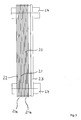
- a plate heat exchanger 20 is shown in front and side view.
- the plate heat exchanger comprises a stack 21 with the arrangement of the single-walled / double-walled Heat exchanger plates 1, 2 according to Figure 1, the single-walled / double-walled Heat exchanger plates 1, 2 permanently connected to each other by means of soldering are.
- the plate heat exchanger 20 further comprises two outer plates 22, 23 with Connections 24 for introducing and discharging the heat exchanger fluids. Between the several Heat exchanger plates 1, 2 are separate flow spaces for the connections 24 introduced / removed heat exchanger fluids formed.
- the heat exchanger fluids are along the heat exchanger plates 1, 2 through the separate flow spaces in Countercurrent led.
- the embossments 6 cause in the central heat transfer sections 3 of the single-walled / double-walled heat exchanger plates 1, 2 a highly turbulent Flow of the heat exchanger fluids between the several heat exchanger plates 1, 2.
- FIG. 4 shows a cross-sectional illustration of the plate heat exchanger 20 according to FIG. 2 a line AA 'in Figure 2.
- the stack 21 in the illustrated embodiment of the plate heat exchanger 20 comprises three double-walled heat exchanger plates 2a, 2b, 2c, each have two plate elements 2a ', 2a ", 2b', 2b" and 2c ', 2c ".
- Both the single-walled as the double-walled heat exchanger plates 1, 2 have one opposite the plane of the central heat transfer section 3 raised edge 26.
- an optional outer edge 27 is formed, which is bent outwards so that the outer edge 27 substantially parallel to the plane of the central heat transfer section 3 runs. In an alternative embodiment, can the outer edge 27 may be omitted.
- heat exchanger fluid is what is due to a leak in one of the two plate elements 2a ', 2a “, 2b', 2b” or 2c ', 2c "between the plate elements 2a', 2a", 2b ', 2b “ or 2c ', 2c "and reaches the region of the edge 26 due to capillary action, already visible from the outside in an area 28.
- the single-walled and double-walled heat exchanger plates 1, 2 each in separate stacks 21a, 21b summarized.
- Heat exchanger plates 1, 2 can be provided, for example with several stacks of single-walled / double-walled heat exchanger plates 1, 2 in a plate heat exchanger.
Landscapes
- Engineering & Computer Science (AREA)
- Physics & Mathematics (AREA)
- Thermal Sciences (AREA)
- Mechanical Engineering (AREA)
- General Engineering & Computer Science (AREA)
- Heat-Exchange Devices With Radiators And Conduit Assemblies (AREA)
- Separation By Low-Temperature Treatments (AREA)
Abstract
Description
- Figur 1
- einen Stapel mit mehreren Wärmeübertragerplatten;
- Figur 2
- eine schematische Darstellung eines Plattenwärmeübertragers in Vorderansicht;
- Figur 3
- eine schematische Darstellung des Plattenwärmeübertragers nach Figur 2 in Seitenansicht;
- Figur 4
- eine Querschnittsdarstellung des Plattenwärmeübertragers nach Figur 2 entlang einer Linie AA' in Figur 2; und
- Figur 5
- eine vergrößerte Darstellung eines Randbereichs der Querschnittsdarstellung in Figur 4.
Claims (2)
- Plattenwärmeübertrager (20) mit einem Stapel (21) von Wärmeübertragerplatten (1, 2), die dauerhaft miteinander verbunden sind und zwischen denen getrennte Durchflußräume für wenigstens zwei Wärmetauscher-Fluide gebildet sind, dadurch gekennzeichnet, daß ein Teil der Wärmeübertragerplatten (1, 2) jeweils als eine einwandige Wärmeübertragerplatte (1) mit einem Plattenelement und ein anderer Teil der Wärmeübertragerplatten (1, 2) jeweils als eine doppelwandige Wärmeübertragerplatte (2) mit zwei Plattenelementen ausgeführt ist.
- Plattenwärmeübertrager nach Anspruch 1, dadurch gekennzeichnet, daß zwischen den Wärmeübertragerplatten (1, 2) getrennte Durchflußräume für drei Wärmetauscher-Fluide gebildet sind.
Applications Claiming Priority (2)
| Application Number | Priority Date | Filing Date | Title |
|---|---|---|---|
| DE10320812A DE10320812B4 (de) | 2003-05-08 | 2003-05-08 | Plattenwärmeübertrager mit einwandigen und doppelwandigen Wärmeübertragerplatten |
| DE10320812 | 2003-05-08 |
Publications (3)
| Publication Number | Publication Date |
|---|---|
| EP1475596A2 true EP1475596A2 (de) | 2004-11-10 |
| EP1475596A3 EP1475596A3 (de) | 2005-10-19 |
| EP1475596B1 EP1475596B1 (de) | 2010-09-01 |
Family
ID=32981301
Family Applications (1)
| Application Number | Title | Priority Date | Filing Date |
|---|---|---|---|
| EP04009741A Expired - Lifetime EP1475596B1 (de) | 2003-05-08 | 2004-04-23 | Plattenwärmeübertrager mit einwandigen und doppelwandigen Wärmeübertragerplatten |
Country Status (7)
| Country | Link |
|---|---|
| US (1) | US6973961B2 (de) |
| EP (1) | EP1475596B1 (de) |
| CN (2) | CN1550746A (de) |
| AT (1) | ATE479874T1 (de) |
| CA (1) | CA2465441C (de) |
| DE (2) | DE10320812B4 (de) |
| NZ (1) | NZ532496A (de) |
Cited By (4)
| Publication number | Priority date | Publication date | Assignee | Title |
|---|---|---|---|---|
| WO2014140131A1 (de) * | 2013-03-12 | 2014-09-18 | Behr Gmbh & Co. Kg | Wärmeübertrager |
| EP2700894A4 (de) * | 2011-04-18 | 2014-12-31 | Mitsubishi Electric Corp | Plattenwärmetauscher und wärmepumpenvorrichtung |
| EP2741041A4 (de) * | 2011-07-13 | 2015-05-27 | Mitsubishi Electric Corp | Plattenwärmetauscher und wärmepumpenvorrichtung |
| EP3404350A4 (de) * | 2016-01-13 | 2019-09-18 | Hisaka Works, Ltd. | Plattenwärmetauscher |
Families Citing this family (14)
| Publication number | Priority date | Publication date | Assignee | Title |
|---|---|---|---|---|
| DE10317263B4 (de) * | 2003-04-14 | 2019-05-29 | Gea Wtt Gmbh | Plattenwärmeübertrager mit doppelwandigen Wärmeübertragerplatten |
| SE532524C2 (sv) * | 2008-06-13 | 2010-02-16 | Alfa Laval Corp Ab | Värmeväxlarplatta samt värmeväxlarmontage innefattandes fyra plattor |
| USD679788S1 (en) * | 2008-10-07 | 2013-04-09 | Swep International Ab | Heat exchanger |
| FI20095267A7 (fi) * | 2009-03-13 | 2010-09-14 | Mauri Kontu | Levylämmönsiirrin ja menetelmä levylämmönsiirtimen paineenkestävyyden parantamiseksi |
| US9163882B2 (en) | 2011-04-25 | 2015-10-20 | Itt Manufacturing Enterprises, Inc. | Plate heat exchanger with channels for ‘leaking fluid’ |
| EP3077752B1 (de) * | 2013-12-05 | 2020-05-13 | SWEP International AB | Wärmetauscher mit verbesserter festigkeit |
| CN105742759B (zh) * | 2016-04-22 | 2019-03-05 | 重庆超力高科技股份有限公司 | 电池冷却液温控装置 |
| CN107917629B (zh) * | 2016-10-11 | 2020-12-18 | 恒丰工程(香港)有限公司 | 双壁板板壳式换热器及其专用双壁换热板 |
| US10809009B2 (en) | 2016-10-14 | 2020-10-20 | Dana Canada Corporation | Heat exchanger having aerodynamic features to improve performance |
| DE112019001344T5 (de) | 2018-03-15 | 2020-12-03 | Mitsubishi Electric Corporation | Plattenwärmetauscher, wärmepumpengerät mit plattenwärmetauscher und wärmepumpentyp eines kühl-, heiz- und warmwasserversorgungssystems mit wärmepumpengerät |
| US11662152B2 (en) | 2018-03-15 | 2023-05-30 | Mitsubishi Electric Corporation | Plate heat exchanger, heat pump device including plate heat exchanger, and heat pump cooling, heating, and hot water supply system including heat pump device |
| US11976895B2 (en) * | 2019-03-18 | 2024-05-07 | Mitsubishi Electric Corporation | Plate heat exchanger and heat pump apparatus including the same |
| JP7567021B2 (ja) * | 2020-07-10 | 2024-10-15 | ハンオン システムズ | 熱交換器 |
| EP4464971A1 (de) * | 2023-05-16 | 2024-11-20 | Danfoss A/S | Wärmetauscher |
Family Cites Families (20)
| Publication number | Priority date | Publication date | Assignee | Title |
|---|---|---|---|---|
| US3537513A (en) * | 1968-03-11 | 1970-11-03 | Garrett Corp | Three-fluid heat exchanger |
| DE2518683C3 (de) * | 1975-04-26 | 1981-04-09 | 4P Verpackungen Gmbh, 8960 Kempten | Wärmeübertrager aus zwei miteinander verbundenen Aluminiumblechen |
| US4249597A (en) * | 1979-05-07 | 1981-02-10 | General Motors Corporation | Plate type heat exchanger |
| JPS5974496A (ja) * | 1982-10-21 | 1984-04-26 | Matsushita Electric Ind Co Ltd | プレ−ト式熱交換器 |
| US4678027A (en) * | 1984-12-14 | 1987-07-07 | Paul Mueller Company | Dual-walled coiled plate heat exchanger with vented interface |
| JP2547231B2 (ja) * | 1986-10-22 | 1996-10-23 | アルフア‐ラヴアル サーマル アーベー | 二重壁構造のプレート型熱交換器とその製造方法 |
| DE3903084A1 (de) * | 1989-02-02 | 1990-08-09 | Bergfeld & Heider Gmbh & Co Kg | Plattenwaermeaustauscher |
| SE9000712L (sv) * | 1990-02-28 | 1991-08-29 | Alfa Laval Thermal | Permanent sammanfogad plattvaermevaexlare |
| SE467275B (sv) * | 1990-05-02 | 1992-06-22 | Alfa Laval Thermal Ab | Loedd dubbelvaeggig plattvaermevaexlare med bockade kanter |
| SE466027B (sv) * | 1990-05-16 | 1991-12-02 | Alfa Laval Thermal Ab | Dubbelvaeggig plattvaermevaexlare med laeckagekanaler tvaers taetningspartierna |
| DE69113039T2 (de) * | 1991-07-08 | 1996-04-18 | Apv Baker As, Kolding | Wärmetauscher mit mehrschichtigen Plattenelementen. |
| US5469914A (en) * | 1993-06-14 | 1995-11-28 | Tranter, Inc. | All-welded plate heat exchanger |
| SE502984C2 (sv) * | 1993-06-17 | 1996-03-04 | Alfa Laval Thermal Ab | Plattvärmeväxlare med speciellt utformade portpartier |
| DE9400502U1 (de) * | 1994-01-13 | 1994-02-24 | Behr Gmbh & Co, 70469 Stuttgart | Wärmetauscher, insbesondere Kältemittelverdampfer |
| US5462113A (en) * | 1994-06-20 | 1995-10-31 | Flatplate, Inc. | Three-circuit stacked plate heat exchanger |
| SE9502135D0 (sv) * | 1995-06-13 | 1995-06-13 | Tetra Laval Holdings & Finance | Plattvärmeväxlare |
| DE19906180C2 (de) * | 1999-02-05 | 2003-02-06 | Peter Rehberg | Plattenwärmeübertrager für Warmwasserbereitung und -speicherung |
| JP2000266479A (ja) * | 1999-03-17 | 2000-09-29 | Daikin Ind Ltd | プレート熱交換器 |
| SE514714C2 (sv) * | 1999-08-27 | 2001-04-09 | Alfa Laval Ab | Lödd plattvärmeväxlare med dubbelväggiga plattor utan inre anliggning mittför lödförbindningarna |
| DE10317263B4 (de) * | 2003-04-14 | 2019-05-29 | Gea Wtt Gmbh | Plattenwärmeübertrager mit doppelwandigen Wärmeübertragerplatten |
-
2003
- 2003-05-08 DE DE10320812A patent/DE10320812B4/de not_active Expired - Fee Related
-
2004
- 2004-04-23 AT AT04009741T patent/ATE479874T1/de active
- 2004-04-23 EP EP04009741A patent/EP1475596B1/de not_active Expired - Lifetime
- 2004-04-23 DE DE502004011600T patent/DE502004011600D1/de not_active Expired - Lifetime
- 2004-04-23 NZ NZ532496A patent/NZ532496A/en unknown
- 2004-04-26 CA CA002465441A patent/CA2465441C/en not_active Expired - Fee Related
- 2004-05-07 US US10/841,084 patent/US6973961B2/en not_active Expired - Fee Related
- 2004-05-08 CN CNA2004100421628A patent/CN1550746A/zh active Pending
- 2004-05-08 CN CNB200610006399XA patent/CN100443848C/zh not_active Expired - Fee Related
Cited By (6)
| Publication number | Priority date | Publication date | Assignee | Title |
|---|---|---|---|---|
| EP2700894A4 (de) * | 2011-04-18 | 2014-12-31 | Mitsubishi Electric Corp | Plattenwärmetauscher und wärmepumpenvorrichtung |
| US9448013B2 (en) | 2011-04-18 | 2016-09-20 | Mitsubishi Electric Corporation | Plate heat exchanger and heat pump apparatus |
| EP2741041A4 (de) * | 2011-07-13 | 2015-05-27 | Mitsubishi Electric Corp | Plattenwärmetauscher und wärmepumpenvorrichtung |
| US9874409B2 (en) | 2011-07-13 | 2018-01-23 | Mitsubishi Electric Corporation | Plate heat exchanger and heat pump apparatus |
| WO2014140131A1 (de) * | 2013-03-12 | 2014-09-18 | Behr Gmbh & Co. Kg | Wärmeübertrager |
| EP3404350A4 (de) * | 2016-01-13 | 2019-09-18 | Hisaka Works, Ltd. | Plattenwärmetauscher |
Also Published As
| Publication number | Publication date |
|---|---|
| EP1475596A3 (de) | 2005-10-19 |
| US6973961B2 (en) | 2005-12-13 |
| CA2465441C (en) | 2008-12-09 |
| CN1550746A (zh) | 2004-12-01 |
| US20040256083A1 (en) | 2004-12-23 |
| NZ532496A (en) | 2005-03-24 |
| CN100443848C (zh) | 2008-12-17 |
| CA2465441A1 (en) | 2004-11-08 |
| CN1847767A (zh) | 2006-10-18 |
| DE10320812B4 (de) | 2007-03-01 |
| DE502004011600D1 (de) | 2010-10-14 |
| HK1092865A1 (zh) | 2007-02-16 |
| DE10320812A1 (de) | 2004-11-25 |
| EP1475596B1 (de) | 2010-09-01 |
| ATE479874T1 (de) | 2010-09-15 |
Similar Documents
| Publication | Publication Date | Title |
|---|---|---|
| EP1475596B1 (de) | Plattenwärmeübertrager mit einwandigen und doppelwandigen Wärmeübertragerplatten | |
| DE112014004486B4 (de) | Wärmetauscher mit integriertem koaxialen Einlass-/Auslassrohr | |
| DE19528117B4 (de) | Wärmeübertrager mit Plattenstapelaufbau | |
| DE112018004787T5 (de) | Multi-fluid wärmetauscher | |
| DE102015010310B4 (de) | Gelöteter Wärmetauscher und Herstellungsverfahren | |
| DE69612664T2 (de) | Plattenwärmetauscher mit gewellten oberflächen | |
| DE102007011762B4 (de) | Wärmetauscher, insbesondere Ölkühler für Kraftfahrzeuge | |
| DE19802012C2 (de) | Gehäuseloser Plattenwärmetauscher | |
| DE112016000793T5 (de) | Flexible Bauweise von Wärmetauschern zum Erwärmen und/oder Kühlen von Flüssigkeiten | |
| DE102016201712A1 (de) | Stapelscheibenwärmetauscher, insbesondere für ein Kraftfahrzeug | |
| DE10317263B4 (de) | Plattenwärmeübertrager mit doppelwandigen Wärmeübertragerplatten | |
| DE102022124354A1 (de) | Wärmeübertrager bestehend aus zwei Arten von Platten | |
| DE2856678C2 (de) | ||
| DE102015209130A1 (de) | Wärmeübertrager | |
| DE60004295T2 (de) | Plattenwärmetauscher, insbesondere zum Kühlen von Kraftfahrzeugöl | |
| WO2017067820A2 (de) | Stapelscheiben-wärmeübertrager | |
| DE102009041526A1 (de) | Plattenwärmetauscher | |
| EP2438384A2 (de) | Sammelrohr für einen kondensator | |
| DE602006000675T2 (de) | Wellrippe für integralgefertigten Wärmetäuscher | |
| DE102021205249B4 (de) | Befestigungseinrichtung für einen Behälter eines Kraftfahrzeugs | |
| DE102012022046A1 (de) | Wärmetauscher | |
| DE60019456T2 (de) | Plattenwärmetauscher | |
| EP2899487A1 (de) | Stapelscheibenwärmeübertrager | |
| EP3191783A1 (de) | Stapelscheiben-wärmeübertrager | |
| DE60003496T2 (de) | Plattenwärmetauscher, insbesondere zum Kühlen von Kraftfahrzeugöl |
Legal Events
| Date | Code | Title | Description |
|---|---|---|---|
| PUAI | Public reference made under article 153(3) epc to a published international application that has entered the european phase |
Free format text: ORIGINAL CODE: 0009012 |
|
| AK | Designated contracting states |
Kind code of ref document: A2 Designated state(s): AT BE BG CH CY CZ DE DK EE ES FI FR GB GR HU IE IT LI LU MC NL PL PT RO SE SI SK TR |
|
| AX | Request for extension of the european patent |
Extension state: AL HR LT LV MK |
|
| PUAL | Search report despatched |
Free format text: ORIGINAL CODE: 0009013 |
|
| AK | Designated contracting states |
Kind code of ref document: A3 Designated state(s): AT BE BG CH CY CZ DE DK EE ES FI FR GB GR HU IE IT LI LU MC NL PL PT RO SE SI SK TR |
|
| AX | Request for extension of the european patent |
Extension state: AL HR LT LV MK |
|
| 17P | Request for examination filed |
Effective date: 20060302 |
|
| AKX | Designation fees paid |
Designated state(s): AT BE BG CH CY CZ DE DK EE ES FI FR GB GR HU IE IT LI LU MC NL PL PT RO SE SI SK TR |
|
| RAP1 | Party data changed (applicant data changed or rights of an application transferred) |
Owner name: GEA WTT GMBH |
|
| 17Q | First examination report despatched |
Effective date: 20090729 |
|
| GRAP | Despatch of communication of intention to grant a patent |
Free format text: ORIGINAL CODE: EPIDOSNIGR1 |
|
| GRAC | Information related to communication of intention to grant a patent modified |
Free format text: ORIGINAL CODE: EPIDOSCIGR1 |
|
| GRAS | Grant fee paid |
Free format text: ORIGINAL CODE: EPIDOSNIGR3 |
|
| GRAA | (expected) grant |
Free format text: ORIGINAL CODE: 0009210 |
|
| AK | Designated contracting states |
Kind code of ref document: B1 Designated state(s): AT BE BG CH CY CZ DE DK EE ES FI FR GB GR HU IE IT LI LU MC NL PL PT RO SE SI SK TR |
|
| REG | Reference to a national code |
Ref country code: GB Ref legal event code: FG4D Free format text: NOT ENGLISH |
|
| REG | Reference to a national code |
Ref country code: CH Ref legal event code: EP |
|
| REG | Reference to a national code |
Ref country code: IE Ref legal event code: FG4D Free format text: LANGUAGE OF EP DOCUMENT: GERMAN |
|
| REF | Corresponds to: |
Ref document number: 502004011600 Country of ref document: DE Date of ref document: 20101014 Kind code of ref document: P |
|
| REG | Reference to a national code |
Ref country code: NL Ref legal event code: VDEP Effective date: 20100901 |
|
| PG25 | Lapsed in a contracting state [announced via postgrant information from national office to epo] |
Ref country code: FI Free format text: LAPSE BECAUSE OF FAILURE TO SUBMIT A TRANSLATION OF THE DESCRIPTION OR TO PAY THE FEE WITHIN THE PRESCRIBED TIME-LIMIT Effective date: 20100901 |
|
| PG25 | Lapsed in a contracting state [announced via postgrant information from national office to epo] |
Ref country code: CY Free format text: LAPSE BECAUSE OF FAILURE TO SUBMIT A TRANSLATION OF THE DESCRIPTION OR TO PAY THE FEE WITHIN THE PRESCRIBED TIME-LIMIT Effective date: 20100901 Ref country code: PL Free format text: LAPSE BECAUSE OF FAILURE TO SUBMIT A TRANSLATION OF THE DESCRIPTION OR TO PAY THE FEE WITHIN THE PRESCRIBED TIME-LIMIT Effective date: 20100901 Ref country code: SI Free format text: LAPSE BECAUSE OF FAILURE TO SUBMIT A TRANSLATION OF THE DESCRIPTION OR TO PAY THE FEE WITHIN THE PRESCRIBED TIME-LIMIT Effective date: 20100901 |
|
| REG | Reference to a national code |
Ref country code: IE Ref legal event code: FD4D |
|
| PG25 | Lapsed in a contracting state [announced via postgrant information from national office to epo] |
Ref country code: GR Free format text: LAPSE BECAUSE OF FAILURE TO SUBMIT A TRANSLATION OF THE DESCRIPTION OR TO PAY THE FEE WITHIN THE PRESCRIBED TIME-LIMIT Effective date: 20101202 Ref country code: NL Free format text: LAPSE BECAUSE OF FAILURE TO SUBMIT A TRANSLATION OF THE DESCRIPTION OR TO PAY THE FEE WITHIN THE PRESCRIBED TIME-LIMIT Effective date: 20100901 Ref country code: SE Free format text: LAPSE BECAUSE OF FAILURE TO SUBMIT A TRANSLATION OF THE DESCRIPTION OR TO PAY THE FEE WITHIN THE PRESCRIBED TIME-LIMIT Effective date: 20100901 |
|
| PG25 | Lapsed in a contracting state [announced via postgrant information from national office to epo] |
Ref country code: IE Free format text: LAPSE BECAUSE OF FAILURE TO SUBMIT A TRANSLATION OF THE DESCRIPTION OR TO PAY THE FEE WITHIN THE PRESCRIBED TIME-LIMIT Effective date: 20100901 |
|
| PG25 | Lapsed in a contracting state [announced via postgrant information from national office to epo] |
Ref country code: SK Free format text: LAPSE BECAUSE OF FAILURE TO SUBMIT A TRANSLATION OF THE DESCRIPTION OR TO PAY THE FEE WITHIN THE PRESCRIBED TIME-LIMIT Effective date: 20100901 Ref country code: EE Free format text: LAPSE BECAUSE OF FAILURE TO SUBMIT A TRANSLATION OF THE DESCRIPTION OR TO PAY THE FEE WITHIN THE PRESCRIBED TIME-LIMIT Effective date: 20100901 Ref country code: CZ Free format text: LAPSE BECAUSE OF FAILURE TO SUBMIT A TRANSLATION OF THE DESCRIPTION OR TO PAY THE FEE WITHIN THE PRESCRIBED TIME-LIMIT Effective date: 20100901 Ref country code: RO Free format text: LAPSE BECAUSE OF FAILURE TO SUBMIT A TRANSLATION OF THE DESCRIPTION OR TO PAY THE FEE WITHIN THE PRESCRIBED TIME-LIMIT Effective date: 20100901 Ref country code: IT Free format text: LAPSE BECAUSE OF FAILURE TO SUBMIT A TRANSLATION OF THE DESCRIPTION OR TO PAY THE FEE WITHIN THE PRESCRIBED TIME-LIMIT Effective date: 20100901 Ref country code: PT Free format text: LAPSE BECAUSE OF FAILURE TO SUBMIT A TRANSLATION OF THE DESCRIPTION OR TO PAY THE FEE WITHIN THE PRESCRIBED TIME-LIMIT Effective date: 20110103 |
|
| PG25 | Lapsed in a contracting state [announced via postgrant information from national office to epo] |
Ref country code: ES Free format text: LAPSE BECAUSE OF FAILURE TO SUBMIT A TRANSLATION OF THE DESCRIPTION OR TO PAY THE FEE WITHIN THE PRESCRIBED TIME-LIMIT Effective date: 20101212 |
|
| PLBE | No opposition filed within time limit |
Free format text: ORIGINAL CODE: 0009261 |
|
| STAA | Information on the status of an ep patent application or granted ep patent |
Free format text: STATUS: NO OPPOSITION FILED WITHIN TIME LIMIT |
|
| 26N | No opposition filed |
Effective date: 20110606 |
|
| PG25 | Lapsed in a contracting state [announced via postgrant information from national office to epo] |
Ref country code: DK Free format text: LAPSE BECAUSE OF FAILURE TO SUBMIT A TRANSLATION OF THE DESCRIPTION OR TO PAY THE FEE WITHIN THE PRESCRIBED TIME-LIMIT Effective date: 20100901 |
|
| REG | Reference to a national code |
Ref country code: DE Ref legal event code: R097 Ref document number: 502004011600 Country of ref document: DE Effective date: 20110606 |
|
| BERE | Be: lapsed |
Owner name: GEA WTT G.M.B.H. Effective date: 20110430 |
|
| PG25 | Lapsed in a contracting state [announced via postgrant information from national office to epo] |
Ref country code: MC Free format text: LAPSE BECAUSE OF NON-PAYMENT OF DUE FEES Effective date: 20110430 |
|
| REG | Reference to a national code |
Ref country code: CH Ref legal event code: PL |
|
| GBPC | Gb: european patent ceased through non-payment of renewal fee |
Effective date: 20110423 |
|
| REG | Reference to a national code |
Ref country code: FR Ref legal event code: ST Effective date: 20111230 |
|
| PG25 | Lapsed in a contracting state [announced via postgrant information from national office to epo] |
Ref country code: LI Free format text: LAPSE BECAUSE OF NON-PAYMENT OF DUE FEES Effective date: 20110430 Ref country code: BE Free format text: LAPSE BECAUSE OF NON-PAYMENT OF DUE FEES Effective date: 20110430 Ref country code: FR Free format text: LAPSE BECAUSE OF NON-PAYMENT OF DUE FEES Effective date: 20110502 Ref country code: DE Free format text: LAPSE BECAUSE OF NON-PAYMENT OF DUE FEES Effective date: 20111101 Ref country code: CH Free format text: LAPSE BECAUSE OF NON-PAYMENT OF DUE FEES Effective date: 20110430 |
|
| REG | Reference to a national code |
Ref country code: DE Ref legal event code: R119 Ref document number: 502004011600 Country of ref document: DE Effective date: 20111101 |
|
| PG25 | Lapsed in a contracting state [announced via postgrant information from national office to epo] |
Ref country code: GB Free format text: LAPSE BECAUSE OF NON-PAYMENT OF DUE FEES Effective date: 20110423 |
|
| REG | Reference to a national code |
Ref country code: AT Ref legal event code: MM01 Ref document number: 479874 Country of ref document: AT Kind code of ref document: T Effective date: 20110423 |
|
| PG25 | Lapsed in a contracting state [announced via postgrant information from national office to epo] |
Ref country code: AT Free format text: LAPSE BECAUSE OF NON-PAYMENT OF DUE FEES Effective date: 20110423 |
|
| PG25 | Lapsed in a contracting state [announced via postgrant information from national office to epo] |
Ref country code: LU Free format text: LAPSE BECAUSE OF NON-PAYMENT OF DUE FEES Effective date: 20110423 |
|
| PG25 | Lapsed in a contracting state [announced via postgrant information from national office to epo] |
Ref country code: TR Free format text: LAPSE BECAUSE OF FAILURE TO SUBMIT A TRANSLATION OF THE DESCRIPTION OR TO PAY THE FEE WITHIN THE PRESCRIBED TIME-LIMIT Effective date: 20100901 Ref country code: BG Free format text: LAPSE BECAUSE OF FAILURE TO SUBMIT A TRANSLATION OF THE DESCRIPTION OR TO PAY THE FEE WITHIN THE PRESCRIBED TIME-LIMIT Effective date: 20101201 |
|
| PG25 | Lapsed in a contracting state [announced via postgrant information from national office to epo] |
Ref country code: HU Free format text: LAPSE BECAUSE OF FAILURE TO SUBMIT A TRANSLATION OF THE DESCRIPTION OR TO PAY THE FEE WITHIN THE PRESCRIBED TIME-LIMIT Effective date: 20100901 |