EP1475550B1 - Reibungskupplung - Google Patents
Reibungskupplung Download PDFInfo
- Publication number
- EP1475550B1 EP1475550B1 EP04009758A EP04009758A EP1475550B1 EP 1475550 B1 EP1475550 B1 EP 1475550B1 EP 04009758 A EP04009758 A EP 04009758A EP 04009758 A EP04009758 A EP 04009758A EP 1475550 B1 EP1475550 B1 EP 1475550B1
- Authority
- EP
- European Patent Office
- Prior art keywords
- pressure plate
- wear
- friction clutch
- arrangement
- adjusting
- Prior art date
- Legal status (The legal status is an assumption and is not a legal conclusion. Google has not performed a legal analysis and makes no representation as to the accuracy of the status listed.)
- Expired - Lifetime
Links
- 230000033001 locomotion Effects 0.000 claims abstract description 19
- 230000005540 biological transmission Effects 0.000 claims description 26
- 230000009977 dual effect Effects 0.000 claims description 5
- 238000000034 method Methods 0.000 claims description 2
- 230000008569 process Effects 0.000 claims description 2
- 238000001514 detection method Methods 0.000 abstract description 23
- 230000008878 coupling Effects 0.000 description 28
- 238000010168 coupling process Methods 0.000 description 28
- 238000005859 coupling reaction Methods 0.000 description 28
- 230000000903 blocking effect Effects 0.000 description 9
- 238000010276 construction Methods 0.000 description 5
- 230000002093 peripheral effect Effects 0.000 description 4
- 230000008859 change Effects 0.000 description 3
- 230000009471 action Effects 0.000 description 2
- 230000000712 assembly Effects 0.000 description 2
- 238000000429 assembly Methods 0.000 description 2
- 238000006073 displacement reaction Methods 0.000 description 2
- 230000000694 effects Effects 0.000 description 2
- 238000009434 installation Methods 0.000 description 2
- 238000005299 abrasion Methods 0.000 description 1
- 230000004323 axial length Effects 0.000 description 1
- 238000005452 bending Methods 0.000 description 1
- 230000009286 beneficial effect Effects 0.000 description 1
- 230000015572 biosynthetic process Effects 0.000 description 1
- 238000002485 combustion reaction Methods 0.000 description 1
- 230000000295 complement effect Effects 0.000 description 1
- 230000007423 decrease Effects 0.000 description 1
- 230000003993 interaction Effects 0.000 description 1
- 238000010248 power generation Methods 0.000 description 1
- 238000004080 punching Methods 0.000 description 1
- 230000009467 reduction Effects 0.000 description 1
Images



Classifications
-
- F—MECHANICAL ENGINEERING; LIGHTING; HEATING; WEAPONS; BLASTING
- F16—ENGINEERING ELEMENTS AND UNITS; GENERAL MEASURES FOR PRODUCING AND MAINTAINING EFFECTIVE FUNCTIONING OF MACHINES OR INSTALLATIONS; THERMAL INSULATION IN GENERAL
- F16D—COUPLINGS FOR TRANSMITTING ROTATION; CLUTCHES; BRAKES
- F16D21/00—Systems comprising a plurality of actuated clutches
- F16D21/02—Systems comprising a plurality of actuated clutches for interconnecting three or more shafts or other transmission members in different ways
- F16D21/06—Systems comprising a plurality of actuated clutches for interconnecting three or more shafts or other transmission members in different ways at least two driving shafts or two driven shafts being concentric
-
- F—MECHANICAL ENGINEERING; LIGHTING; HEATING; WEAPONS; BLASTING
- F16—ENGINEERING ELEMENTS AND UNITS; GENERAL MEASURES FOR PRODUCING AND MAINTAINING EFFECTIVE FUNCTIONING OF MACHINES OR INSTALLATIONS; THERMAL INSULATION IN GENERAL
- F16D—COUPLINGS FOR TRANSMITTING ROTATION; CLUTCHES; BRAKES
- F16D13/00—Friction clutches
- F16D13/58—Details
- F16D13/75—Features relating to adjustment, e.g. slack adjusters
- F16D13/757—Features relating to adjustment, e.g. slack adjusters the adjusting device being located on or inside the clutch cover, e.g. acting on the diaphragm or on the pressure plate
-
- F—MECHANICAL ENGINEERING; LIGHTING; HEATING; WEAPONS; BLASTING
- F16—ENGINEERING ELEMENTS AND UNITS; GENERAL MEASURES FOR PRODUCING AND MAINTAINING EFFECTIVE FUNCTIONING OF MACHINES OR INSTALLATIONS; THERMAL INSULATION IN GENERAL
- F16D—COUPLINGS FOR TRANSMITTING ROTATION; CLUTCHES; BRAKES
- F16D21/00—Systems comprising a plurality of actuated clutches
- F16D21/02—Systems comprising a plurality of actuated clutches for interconnecting three or more shafts or other transmission members in different ways
- F16D21/06—Systems comprising a plurality of actuated clutches for interconnecting three or more shafts or other transmission members in different ways at least two driving shafts or two driven shafts being concentric
- F16D2021/0607—Double clutch with torque input plate in-between the two clutches, i.e. having a central input plate
-
- F—MECHANICAL ENGINEERING; LIGHTING; HEATING; WEAPONS; BLASTING
- F16—ENGINEERING ELEMENTS AND UNITS; GENERAL MEASURES FOR PRODUCING AND MAINTAINING EFFECTIVE FUNCTIONING OF MACHINES OR INSTALLATIONS; THERMAL INSULATION IN GENERAL
- F16D—COUPLINGS FOR TRANSMITTING ROTATION; CLUTCHES; BRAKES
- F16D21/00—Systems comprising a plurality of actuated clutches
- F16D21/02—Systems comprising a plurality of actuated clutches for interconnecting three or more shafts or other transmission members in different ways
- F16D21/06—Systems comprising a plurality of actuated clutches for interconnecting three or more shafts or other transmission members in different ways at least two driving shafts or two driven shafts being concentric
- F16D2021/0684—Mechanically actuated clutches with two clutch plates
-
- F—MECHANICAL ENGINEERING; LIGHTING; HEATING; WEAPONS; BLASTING
- F16—ENGINEERING ELEMENTS AND UNITS; GENERAL MEASURES FOR PRODUCING AND MAINTAINING EFFECTIVE FUNCTIONING OF MACHINES OR INSTALLATIONS; THERMAL INSULATION IN GENERAL
- F16D—COUPLINGS FOR TRANSMITTING ROTATION; CLUTCHES; BRAKES
- F16D2300/00—Special features for couplings or clutches
- F16D2300/14—Clutches which are normally open, i.e. not engaged in released state
Definitions
- the present invention relates to a friction clutch comprising a housing assembly, a movable in the housing assembly in the direction of a rotation axis held pressure plate, a respect to the housing assembly and the pressure plate supporting Kraftbeaufschlagungsaniser, a wear adjuster in the power transmission path between the pressure plate and the Kraftbeaufschlagungsan whatsoever, comprising at least one displaceable for wear adjustment Adjustment element, provided on the pressure plate detection element, that with a detection section when wear occurs in plant can come a stop and is movable with respect to the pressure plate, a wedge-like locking element, which the detection element with respect to movement the pressure plate locked against return movement, wherein the locking element by a biasing arrangement towards a sensing element against Return movement arresting state is biased.
- a friction clutch is known from US 2003/0062237 A1.
- Double couplings are used, through which either the drive, so a Internal combustion engine to be coupled with one of the two transmission input shafts can.
- Such friction clutches also known as dual clutches, include two generally axially staggered coupling areas, the corresponding axial volume claim.
- the aim of the present invention is to provide such a friction clutch with the possibility compensate for occurring wear, so that the claimed axial space can be reduced.
- a friction clutch comprising a housing assembly, one in the housing assembly in the direction of a Rotary axis held movable pressure plate, one with respect to the housing assembly and the pressure plate supporting Kraftbeaufyerungsan 11, a Wear adjusting device in the power transmission path between the pressure plate and the Kraftbeaufschlagungsan 11, comprising at least one for wear adjustment displaceable adjusting element, one provided on the pressure plate Detecting element, which with a detection section in case of wear can come into contact with a stop and thereby with respect to the pressure plate is movable, a wedge-like locking element, which the detection element after Movement with respect to the pressure plate locked against return movement, wherein the locking element by a biasing arrangement towards a sensing element is biased against return movement arresting state, the at least an adjusting element and the pressure plate with respect to each other radially staggered are arranged.
- the at least one adjusting element is an adjusting ring, which on reason its closed ring-like body absorbs centrifugal forces in itself.
- At the pressure plate at least a the at least one adjusting element axially supporting and radially projecting Supporting area is provided. It should be noted that nevertheless in the context of the present invention with partially radially outwardly and the wear adjuster at least partially radially overlapping areas the substantial body portion of the pressure plate with respect to the wear adjusting device continues to be regarded as radially staggered.
- the stop with which cooperate the detection element in case of wear may preferably be fixed to the housing assembly.
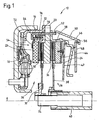
- an inventively designed double clutch is generally designated 10.
- the dual clutch 10 includes a housing assembly 12 having a first one Housing part 14, which via a Torsionsschwingungsdämpferan extract 16 for coupled common rotation with a crankshaft or other drive shaft can be.
- a second housing part 18 is provided, wherein the two housing parts 14, 16 positioned on the two axial sides of an intermediate plate 20 are and are firmly connected with it.
- the dual clutch 10 are the two pressure plates 22, 24 of the two coupling areas 26, 28 of the double clutch 10 is provided.
- the two pressure plates 22, 24 For example, with the housing parts 14 and 18 or the intermediate plate 20 rotationally fixed, with respect to the intermediate plate 20, however, be coupled axially movable.
- tangential leaf springs for this purpose, so-called tangential leaf springs or the like can be used.
- Die Clutch disc 32 is connected to a first transmission input shaft 34 of a not shown Gear coupled for common rotation about the axis of rotation A.
- This Kraftbeetzhausungsan Aunt 46 also includes in construction as a so-called normal-open coupling a plurality of lever segments 48 or the like, which, as well as the Kraftbeaufschlagungsan whatsoever 42 of the coupling portion 28, with respect to the housing part 18 support and two, for example, pot-shaped or shell-like power transmission elements 50, 52, which axially bridge the intermediate plate 20, an actuating force lead in the direction of the pressure plate 22. Also in the power transmission path between this Kraftbeaufleyungsan ever 46, namely the power transmission element 52 thereof, and the pressure plate 22 is a generally designated 54 Wear compensator.
- the wear adjustment device 54 comprises, for example, two readjusting rings 56, 58 which are staggered axially relative to one another and which surround the pressure plate 22 substantially radially on the outside.
- the adjusting ring 58 is axially supported on a support region 60 of the pressure plate 22 which engages radially outward.
- the adjusting ring 56 is acted upon by Einschkraftbeaufschlagung the pressure plate 22 by the power transmission element 52 axially.
- There is an example formed as a helical tension spring biasing spring 62 is present, which is mounted in an end portion of a rivet bolt 64.
- This rivet bolt 64 which is attached to a radially outwardly gripping mounting portion 66 of the pressure plate 22, at the same time serve also to firmly connect the above-mentioned tangential leaf springs or the like with the pressure plate 22.
- the biasing spring 62 is attached to the adjuster ring 58 which is supported on the support region 60.
- force F 1 is generated, which tries to turn the adjusting ring 58 in the circumferential direction.
- the two axially adjoining adjusting rings 56, 58 abut each other in the area of ramp surfaces 68, 70.
- a rotation of the adjusting ring 58, induced by the force F 1 would thus result in an increase in the total axial extent of the two adjoining adjusting rings 56, 58 and the wear adjusting device 54 substantially provided by them.
- detection element 72 is provided on the pressure plate 22. This extends radially outward and engages through a recess 74 of the Adjustment ring 56 through. Since the detection element 72 on the pressure plate 22nd is determined by this engagement in the recess 74 and the adjusting ring 56 with respect to the pressure plate 22 held against rotation. The detection element 72 stretches further radially outward and overlaps there in the radial direction and also in the circumferential direction with a on the housing assembly 12 and the intermediate plate 20 fixed blocking element 76th
- a wedge-shaped slide locking member 78 is provided. This is arranged on the outer peripheral side of the adjusting rings 56, 58 and is supported, for example, by the sections 66, which are also visible in Figures 4 and 5, radially outward. Also for the locking element 78, a biasing spring is provided which generates a force F 2 to bias this component for movement in the circumferential direction.
- this biasing spring is fixed in one end to the locking element 78 and in the other end to a fixed element, for example, a rivet bolt 64 or the biasing spring 62 in that end region in which this is attached to the adjusting ring 58, is fixed.
- the pressure plate 22 will move closer to the intermediate plate 20 than is the case in a new, non-wearing condition. In this case, the state will occur in which the detection element 72 comes radially outward in contact with the blocking element 76 and thus at least in this radially outer region of the further axial displacement of the pressure plate 22 can not follow. The sensing element 72 thus moves axially with respect to the pressure plate, so that the axial gap between the sensing element 72 and the support portion 60 increases where the locking member 78 is positioned increases.
- the detection element 72 In the course of this relative movement of the detection element 72 with respect to the pressure plate 22, the detection element 72 thus lifts off the adjusting ring 56, and due to the increasing gap between this detection element 72 and the support region 60, the locking element 78 by the action of the force F 2 correspondingly shift in the circumferential direction.
- the adjusting ring 56 continues to be under the action of the power transmission member 52, it can not move despite the fact that it is no longer hindered from moving in the axial direction by the detecting member 72.
- the detection element 72 can not move back into its initial position by the locking element 78, which is displaced slightly in the circumferential direction.
- the clamping of the readjusting rings 56, 58 between the pressure plate 22 and the force transmission element 52 is defined, for example, by the release force, which can be provided by the tangential leaf springs or the like.
- the release force can be provided by the tangential leaf springs or the like.
- the Arresting element 78 is positioned offset in the circumferential direction to the biasing spring 62nd for the adjusting ring 58, to mutual interference or overlapping of these components to avoid.
- the wear adjuster 54 only one may include single adjusting ring, which is then movable in the circumferential direction, to an axial side is acted upon by the force transmission element 52 and at the other axial side with its wedge surface or its wedge surfaces of complementary Is supported surfaces that directly on the pressure plate 22, so for example the support area 60 are provided.
- the illustrated or described adjusting rings and individual wedge-like slide elements provide.
- due to the centrifugal effect is particular in the radial staggering the provision of ring-closed adjusting elements advantageous.
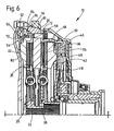
- FIG. 6 A modified embodiment of the above-described double clutch is shown in FIG. Also in the double clutch 10 shown in FIG. 6 forms the Intermediate plate 20 an abutment for the two coupling portions 26 and 28.
- the connection of the double clutch 10 and the housing assembly 12 thereof provided directly over the intermediate plate 20 or sections provided thereon, via a flex plate 82 or the like to the drive shaft, not shown are rotatably connected. Again, however, are on both sides of the intermediate plate 20, the two pressure plates 22, 24 are provided. While here at the pressure plate 24 of the coupling portion 28 is shown no wear adjusting device is in Assignment to the pressure plate 22 again the wear adjusting device described in detail above 54 provided with the associated components.
- the support region 60 has a section on the pressure plate 22, which engages over the adjusting ring 58 and also the locking element 78 on the outside and thus a radial support for the limited in the circumferential direction only extending locking member 78 provides.
- the detection element 72 is a for example, by punching and bending a tab formed Radialabstützvorsprung 84 formed on the other axial side of the locking element 78th supported radially outward.
- the blocking element 76 is here as an integral part also to be considered as part of the housing assembly 12 intermediate plate 20 executed.
- the pressure plate 20 may be provided a wear adjustment device, the constructed according to the principles of the present invention, so with radial staggering the pressure plate 20 and an adjusting element, which in turn here for example could be positioned on the inner peripheral side of the pressure plate 20.
- FIG. 7 shows a further embodiment of a dual-clutch arrangement according to the invention 10. It can be seen that in the embodiment according to Fig. 7, the intermediate plate 20 forms only the abutment for the coupling portion 28.
- the coupling portion 26 is a radially outward with the intermediate plate 20 through Bolt or the like firmly connected and a secondary mass of the torsional vibration damper assembly 16 forming flywheel 20 'as an abutment intended.
- With the intermediate plate 20 are now two housing parts 18, 18 'on the same axial side fixed to which the two lever assemblies or Kraftbeetzschungsan angelen 42, 48 of the two coupling portions 28, 26 in their respective radially outer region are supported.
Landscapes
- Engineering & Computer Science (AREA)
- General Engineering & Computer Science (AREA)
- Mechanical Engineering (AREA)
- Mechanical Operated Clutches (AREA)
- Braking Arrangements (AREA)
Description
- Fig. 1
- eine Teil-Längsschnittansicht einer erfindungsgemäß aufgebauten Doppelkupplung;
- Fig. 2
- eine Detail-Längsschnittansicht der erfindungsgemäßen Doppelkupplung in einer anderen Ebene geschnitten;
- Fig. 3
- eine Ansicht der erfindungsgemäßen Doppelkupplung von radial außen, teilweise geschnitten;
- Fig. 4
- eine Detailansicht der auch in Fig. 2 erkennbaren Anpressplatte;
- Fig. 5
- eine Axialansicht des in Fig. 4 dargestellten Details;
- Fig. 6
- eine der Fig. 1 entsprechende Ansicht einer alternativen Doppelkupplung;
- Fig. 7
- eine weitere alternative Ausgestaltungsform einer Doppelkupplung.
Claims (7)
- Reibungskupplung, umfassend:das wenigstens eine Nachstellelement (56, 58) und die Anpressplatte (22) bezüglich einander radial gestaffelt angeordnet sind.eine Gehäuseanordnung (12),eine in der Gehäuseanordnung (12) in Richtung einer Drehachse (A) bewegbar gehaltene Anpressplatte (22, 24),eine sich bezüglich der Gehäuseanordnung (12) und der Anpressplatte (22) abstützende Kraftbeaufschlagungsanordnung (46),eine Verschleißnachstellvorrichtung (54) im Kraftübertragungsweg zwischen der Anpressplatte (22) und der Kraftbeaufschlagungsanordnung (46), umfassend wenigstens ein zur Verschleißnachstellung verlagerbares Nachstellelement (56, 58),ein an der Anpressplatte (22) vorgesehenes Erfassungselement (72), das mit einem Erfassungsabschnitt bei Auftreten von Verschleiß in Anlage an einem Anschlag (76) kommen kann und dabei bezüglich der Anpressplatte (22) bewegbar ist,ein keilartiges Arretierelement (78), welches das Erfassungselement (78) nach Bewegung bezüglich der Anpressplatte (22) gegen Rückbewegung arretiert, wobei das Arretierelement (78) durch eine Vorspannanordnung (F2) in Richtung zu einem das Erfassungselement (72) gegen Rückbewegung arretierenden Zustand vorgespannt ist, dadurch gekennzeichnet, dass
- Reibungskupplung nach Anspruch 1,
dadurch gekennzeichnet, dass das wenigstens eine Nachstellelement (56, 58) radial außen bezüglich der Anpressplatte (22) angeordnet ist. - Reibungskupplung nach Anspruch 1 oder 2,
dadurch gekennzeichnet, dass das wenigstens eine Nachstellelement (56, 58) ein Nachstellring (56, 58) ist. - Reibungskupplung nach einem der Ansprüche 1 bis 3,
dadurch gekennzeichnet, dass an der Anpressplatte (22) wenigstens ein das wenigstens eine Nachstellelement (56, 58) axial stützender und radial vorspringender (60) Stützbereich vorgesehen ist. - Reibungskupplung nach einem der Ansprüche 1 bis 4,
dadurch gekennzeichnet, dass der Anschlag (76) bezüglich der Gehäuseanordnung (12) feststeht. - Reibungskupplung nach einem der Ansprüche 1 bis 5,
dadurch gekennzeichnet, dass eine Zwischenplatte (26) vorgesehen ist, an deren beiden axialen Seiten jeweils eine Anpressplatte (22, 24) eines jeweiligen Kupplungsbereichs (26, 28) einer Doppelkupplung vorgesehen ist, wobei die Zwischenplatte (20) für wenigstens einen Kupplungsbereich (26, 28) ein Widerlager bildet, wobei jeder Anpressplatte (22, 24) eine Kraftbeaufschlagungsanordnung (46, 42) zugeordnet ist und im Kraftübertragungsweg zwischen wenigstens einer Anpressplatte (22, 24) und der zugeordneten Kraftbeaufschlagungsanordnung (46, 42) eine Verschleißnachstellvorrichtung (54, 44) mit zugeordnetem Arretierelement (78) und Erfassungselement (72) vorgesehen ist. - Reibungskupplung nach Anspruch 6,
dadurch gekennzeichnet, dass eine (46) der Kraftbeaufschlagungsanordnungen (46, 42) die Zwischenplatte (20) axial überbrückt und dass wenigstens im Kraftübertragungsweg zwischen dieser Kraftbeaufschlagungsanordnung (46) und der dadurch beaufschlagten Anpressplatte (22) eine Verschleißnachstellvorrichtung (54) mit zugeordnetem Arretierelement (78) und Erfassungselement (72) vorgesehen ist.
Applications Claiming Priority (2)
| Application Number | Priority Date | Filing Date | Title |
|---|---|---|---|
| DE10319999 | 2003-05-06 | ||
| DE10319999 | 2003-05-06 |
Publications (2)
| Publication Number | Publication Date |
|---|---|
| EP1475550A1 EP1475550A1 (de) | 2004-11-10 |
| EP1475550B1 true EP1475550B1 (de) | 2005-12-07 |
Family
ID=32981221
Family Applications (1)
| Application Number | Title | Priority Date | Filing Date |
|---|---|---|---|
| EP04009758A Expired - Lifetime EP1475550B1 (de) | 2003-05-06 | 2004-04-24 | Reibungskupplung |
Country Status (3)
| Country | Link |
|---|---|
| EP (1) | EP1475550B1 (de) |
| AT (1) | ATE312298T1 (de) |
| DE (2) | DE502004000163D1 (de) |
Families Citing this family (3)
| Publication number | Priority date | Publication date | Assignee | Title |
|---|---|---|---|---|
| DE102006019977B4 (de) * | 2005-05-19 | 2018-01-04 | Schaeffler Technologies AG & Co. KG | Drehmomentübertragungseinrichtung |
| EP1748206A3 (de) * | 2005-05-19 | 2007-02-21 | LuK Lamellen und Kupplungsbau Beteiligungs KG | Drehmomentübertragungseinrichtung |
| CN102356250B (zh) | 2009-04-27 | 2014-12-03 | 舍弗勒技术股份两合公司 | 离合器 |
Family Cites Families (4)
| Publication number | Priority date | Publication date | Assignee | Title |
|---|---|---|---|---|
| GB2242945B (en) * | 1990-04-11 | 1994-02-02 | Honda Motor Co Ltd | Multiple-disk clutch apparatus |
| US5404979A (en) * | 1994-05-27 | 1995-04-11 | Chrysler Corporation | Motor vehicle manual transmission modular clutch assembly |
| JP2000274448A (ja) * | 1999-03-23 | 2000-10-03 | Exedy Corp | ツインクラッチ |
| DE10148434A1 (de) * | 2001-10-01 | 2003-04-17 | Zf Sachs Ag | Druckplattenbaugruppe für eine Reigungskupplung |
-
2004
- 2004-04-24 DE DE502004000163T patent/DE502004000163D1/de not_active Expired - Lifetime
- 2004-04-24 AT AT04009758T patent/ATE312298T1/de not_active IP Right Cessation
- 2004-04-24 EP EP04009758A patent/EP1475550B1/de not_active Expired - Lifetime
- 2004-04-27 DE DE102004020634A patent/DE102004020634A1/de not_active Withdrawn
Also Published As
| Publication number | Publication date |
|---|---|
| EP1475550A1 (de) | 2004-11-10 |
| ATE312298T1 (de) | 2005-12-15 |
| DE102004020634A1 (de) | 2004-11-18 |
| DE502004000163D1 (de) | 2006-01-12 |
Similar Documents
| Publication | Publication Date | Title |
|---|---|---|
| EP1499811B1 (de) | Kupplungsaggregat | |
| EP3069037B1 (de) | Kupplungsaggregat | |
| DE4440412C2 (de) | Reibungskupplung mit automatischem Verschleißausgleich | |
| EP1134447B1 (de) | Doppelkupplungsanordnung | |
| EP1298339B1 (de) | Mehrfach-Kupplungsanordnung, insbesondere Doppelkupplungsanordnung | |
| DE9219181U1 (de) | Reibungskupplung | |
| DE102019204349A1 (de) | Druckfluid-Betätigungsanordnung für eine Reibungskupplung | |
| EP1512881B1 (de) | Kupplungsaggregat | |
| EP1302687B1 (de) | Mehrfach-Kupplungsanordnung | |
| DE69705563T2 (de) | Kupplungsgehäuse mit Abnutzausgleichmechanismus | |
| DE2736518C3 (de) | Ausrück-Hilfseinrichtung für eine Reibungskupplung, insbesondere eines Kraftfahrzeuges | |
| EP1862688B2 (de) | Drehmomentübertragungsanordnung für den Antriebsstrang eines Fahrzeugs | |
| DE102012213684A1 (de) | Zugankeranordnung zum Verlagern einer Anpressplatte einer Reibungskupplung | |
| DE10018646B4 (de) | Doppelkupplungsanordnung | |
| DE10241027A1 (de) | Mehrfach-Kupplungsanordnung | |
| EP1475550A1 (de) | Reibungskupplung | |
| EP1375944B1 (de) | Druckplattenbaugruppe für eine Reibungskupplung | |
| DE10148427A1 (de) | Verfahren zum Justieren eines Reibungskupplungssystems | |
| DE10049649A1 (de) | Druckplattenbaugruppe | |
| DE10126776A1 (de) | Druckplattenbaugruppe | |
| WO2003029675A1 (de) | Druckplattenbaugruppe für eine reibungskupplung | |
| DE102019204360A1 (de) | Druckfluid-Betätigungsanordnung für eine Reibungskupplung | |
| EP1298338B1 (de) | Druckplattenbaugruppe für eine Reibungskupplung | |
| EP1916435B1 (de) | Kupplungssystem | |
| DE10201914B4 (de) | Reibungskupplung |
Legal Events
| Date | Code | Title | Description |
|---|---|---|---|
| PUAI | Public reference made under article 153(3) epc to a published international application that has entered the european phase |
Free format text: ORIGINAL CODE: 0009012 |
|
| AK | Designated contracting states |
Kind code of ref document: A1 Designated state(s): AT BE BG CH CY CZ DE DK EE ES FI FR GB GR HU IE IT LI LU MC NL PL PT RO SE SI SK TR |
|
| AX | Request for extension of the european patent |
Extension state: AL HR LT LV MK |
|
| 17P | Request for examination filed |
Effective date: 20040916 |
|
| GRAP | Despatch of communication of intention to grant a patent |
Free format text: ORIGINAL CODE: EPIDOSNIGR1 |
|
| AKX | Designation fees paid |
Designated state(s): AT BE BG CH CY CZ DE DK EE ES FI FR GB GR HU IE IT LI LU MC NL PL PT RO SE SI SK TR |
|
| GRAS | Grant fee paid |
Free format text: ORIGINAL CODE: EPIDOSNIGR3 |
|
| GRAA | (expected) grant |
Free format text: ORIGINAL CODE: 0009210 |
|
| AK | Designated contracting states |
Kind code of ref document: B1 Designated state(s): AT BE BG CH CY CZ DE DK EE ES FI FR GB GR HU IE IT LI LU MC NL PL PT RO SE SI SK TR |
|
| PG25 | Lapsed in a contracting state [announced via postgrant information from national office to epo] |
Ref country code: CZ Free format text: LAPSE BECAUSE OF FAILURE TO SUBMIT A TRANSLATION OF THE DESCRIPTION OR TO PAY THE FEE WITHIN THE PRESCRIBED TIME-LIMIT Effective date: 20051207 Ref country code: SI Free format text: LAPSE BECAUSE OF FAILURE TO SUBMIT A TRANSLATION OF THE DESCRIPTION OR TO PAY THE FEE WITHIN THE PRESCRIBED TIME-LIMIT Effective date: 20051207 Ref country code: FI Free format text: LAPSE BECAUSE OF FAILURE TO SUBMIT A TRANSLATION OF THE DESCRIPTION OR TO PAY THE FEE WITHIN THE PRESCRIBED TIME-LIMIT Effective date: 20051207 Ref country code: IT Free format text: LAPSE BECAUSE OF FAILURE TO SUBMIT A TRANSLATION OF THE DESCRIPTION OR TO PAY THE FEE WITHIN THE PRESCRIBED TIME-LIMIT;WARNING: LAPSES OF ITALIAN PATENTS WITH EFFECTIVE DATE BEFORE 2007 MAY HAVE OCCURRED AT ANY TIME BEFORE 2007. THE CORRECT EFFECTIVE DATE MAY BE DIFFERENT FROM THE ONE RECORDED. Effective date: 20051207 Ref country code: SK Free format text: LAPSE BECAUSE OF FAILURE TO SUBMIT A TRANSLATION OF THE DESCRIPTION OR TO PAY THE FEE WITHIN THE PRESCRIBED TIME-LIMIT Effective date: 20051207 Ref country code: PL Free format text: LAPSE BECAUSE OF FAILURE TO SUBMIT A TRANSLATION OF THE DESCRIPTION OR TO PAY THE FEE WITHIN THE PRESCRIBED TIME-LIMIT Effective date: 20051207 Ref country code: NL Free format text: LAPSE BECAUSE OF FAILURE TO SUBMIT A TRANSLATION OF THE DESCRIPTION OR TO PAY THE FEE WITHIN THE PRESCRIBED TIME-LIMIT Effective date: 20051207 Ref country code: IE Free format text: LAPSE BECAUSE OF FAILURE TO SUBMIT A TRANSLATION OF THE DESCRIPTION OR TO PAY THE FEE WITHIN THE PRESCRIBED TIME-LIMIT Effective date: 20051207 Ref country code: RO Free format text: LAPSE BECAUSE OF FAILURE TO SUBMIT A TRANSLATION OF THE DESCRIPTION OR TO PAY THE FEE WITHIN THE PRESCRIBED TIME-LIMIT Effective date: 20051207 |
|
| REG | Reference to a national code |
Ref country code: GB Ref legal event code: FG4D Free format text: NOT ENGLISH |
|
| REG | Reference to a national code |
Ref country code: CH Ref legal event code: EP |
|
| REG | Reference to a national code |
Ref country code: IE Ref legal event code: FG4D Free format text: LANGUAGE OF EP DOCUMENT: GERMAN |
|
| REF | Corresponds to: |
Ref document number: 502004000163 Country of ref document: DE Date of ref document: 20060112 Kind code of ref document: P |
|
| PG25 | Lapsed in a contracting state [announced via postgrant information from national office to epo] |
Ref country code: GR Free format text: LAPSE BECAUSE OF FAILURE TO SUBMIT A TRANSLATION OF THE DESCRIPTION OR TO PAY THE FEE WITHIN THE PRESCRIBED TIME-LIMIT Effective date: 20060307 Ref country code: BG Free format text: LAPSE BECAUSE OF FAILURE TO SUBMIT A TRANSLATION OF THE DESCRIPTION OR TO PAY THE FEE WITHIN THE PRESCRIBED TIME-LIMIT Effective date: 20060307 Ref country code: DK Free format text: LAPSE BECAUSE OF FAILURE TO SUBMIT A TRANSLATION OF THE DESCRIPTION OR TO PAY THE FEE WITHIN THE PRESCRIBED TIME-LIMIT Effective date: 20060307 Ref country code: SE Free format text: LAPSE BECAUSE OF FAILURE TO SUBMIT A TRANSLATION OF THE DESCRIPTION OR TO PAY THE FEE WITHIN THE PRESCRIBED TIME-LIMIT Effective date: 20060307 |
|
| GBT | Gb: translation of ep patent filed (gb section 77(6)(a)/1977) |
Effective date: 20060214 |
|
| PG25 | Lapsed in a contracting state [announced via postgrant information from national office to epo] |
Ref country code: ES Free format text: LAPSE BECAUSE OF FAILURE TO SUBMIT A TRANSLATION OF THE DESCRIPTION OR TO PAY THE FEE WITHIN THE PRESCRIBED TIME-LIMIT Effective date: 20060318 |
|
| PG25 | Lapsed in a contracting state [announced via postgrant information from national office to epo] |
Ref country code: AT Free format text: LAPSE BECAUSE OF NON-PAYMENT OF DUE FEES Effective date: 20060424 |
|
| PG25 | Lapsed in a contracting state [announced via postgrant information from national office to epo] |
Ref country code: MC Free format text: LAPSE BECAUSE OF NON-PAYMENT OF DUE FEES Effective date: 20060430 Ref country code: BE Free format text: LAPSE BECAUSE OF NON-PAYMENT OF DUE FEES Effective date: 20060430 |
|
| PG25 | Lapsed in a contracting state [announced via postgrant information from national office to epo] |
Ref country code: PT Free format text: LAPSE BECAUSE OF FAILURE TO SUBMIT A TRANSLATION OF THE DESCRIPTION OR TO PAY THE FEE WITHIN THE PRESCRIBED TIME-LIMIT Effective date: 20060508 |
|
| NLV1 | Nl: lapsed or annulled due to failure to fulfill the requirements of art. 29p and 29m of the patents act | ||
| PG25 | Lapsed in a contracting state [announced via postgrant information from national office to epo] |
Ref country code: HU Free format text: LAPSE BECAUSE OF FAILURE TO SUBMIT A TRANSLATION OF THE DESCRIPTION OR TO PAY THE FEE WITHIN THE PRESCRIBED TIME-LIMIT Effective date: 20060608 |
|
| ET | Fr: translation filed | ||
| REG | Reference to a national code |
Ref country code: IE Ref legal event code: FD4D |
|
| PLBE | No opposition filed within time limit |
Free format text: ORIGINAL CODE: 0009261 |
|
| STAA | Information on the status of an ep patent application or granted ep patent |
Free format text: STATUS: NO OPPOSITION FILED WITHIN TIME LIMIT |
|
| 26N | No opposition filed |
Effective date: 20060908 |
|
| BERE | Be: lapsed |
Owner name: ZF SACHS A.G. Effective date: 20060430 |
|
| PG25 | Lapsed in a contracting state [announced via postgrant information from national office to epo] |
Ref country code: EE Free format text: LAPSE BECAUSE OF FAILURE TO SUBMIT A TRANSLATION OF THE DESCRIPTION OR TO PAY THE FEE WITHIN THE PRESCRIBED TIME-LIMIT Effective date: 20051207 |
|
| PG25 | Lapsed in a contracting state [announced via postgrant information from national office to epo] |
Ref country code: LU Free format text: LAPSE BECAUSE OF NON-PAYMENT OF DUE FEES Effective date: 20060424 Ref country code: TR Free format text: LAPSE BECAUSE OF FAILURE TO SUBMIT A TRANSLATION OF THE DESCRIPTION OR TO PAY THE FEE WITHIN THE PRESCRIBED TIME-LIMIT Effective date: 20051207 |
|
| PG25 | Lapsed in a contracting state [announced via postgrant information from national office to epo] |
Ref country code: CY Free format text: LAPSE BECAUSE OF FAILURE TO SUBMIT A TRANSLATION OF THE DESCRIPTION OR TO PAY THE FEE WITHIN THE PRESCRIBED TIME-LIMIT Effective date: 20051207 |
|
| REG | Reference to a national code |
Ref country code: CH Ref legal event code: PL |
|
| PG25 | Lapsed in a contracting state [announced via postgrant information from national office to epo] |
Ref country code: LI Free format text: LAPSE BECAUSE OF NON-PAYMENT OF DUE FEES Effective date: 20080430 Ref country code: CH Free format text: LAPSE BECAUSE OF NON-PAYMENT OF DUE FEES Effective date: 20080430 |
|
| PGFP | Annual fee paid to national office [announced via postgrant information from national office to epo] |
Ref country code: FR Payment date: 20090417 Year of fee payment: 6 |
|
| PGFP | Annual fee paid to national office [announced via postgrant information from national office to epo] |
Ref country code: GB Payment date: 20090422 Year of fee payment: 6 |
|
| GBPC | Gb: european patent ceased through non-payment of renewal fee |
Effective date: 20100424 |
|
| REG | Reference to a national code |
Ref country code: FR Ref legal event code: ST Effective date: 20101230 |
|
| PG25 | Lapsed in a contracting state [announced via postgrant information from national office to epo] |
Ref country code: GB Free format text: LAPSE BECAUSE OF NON-PAYMENT OF DUE FEES Effective date: 20100424 |
|
| PG25 | Lapsed in a contracting state [announced via postgrant information from national office to epo] |
Ref country code: FR Free format text: LAPSE BECAUSE OF NON-PAYMENT OF DUE FEES Effective date: 20100430 |
|
| REG | Reference to a national code |
Ref country code: DE Ref legal event code: R081 Ref document number: 502004000163 Country of ref document: DE Owner name: ZF FRIEDRICHSHAFEN AG, DE Free format text: FORMER OWNER: ZF SACHS AG, 97424 SCHWEINFURT, DE Effective date: 20121030 |
|
| PGFP | Annual fee paid to national office [announced via postgrant information from national office to epo] |
Ref country code: DE Payment date: 20130508 Year of fee payment: 10 |
|
| REG | Reference to a national code |
Ref country code: DE Ref legal event code: R119 Ref document number: 502004000163 Country of ref document: DE |
|
| REG | Reference to a national code |
Ref country code: DE Ref legal event code: R119 Ref document number: 502004000163 Country of ref document: DE Effective date: 20141101 |
|
| PG25 | Lapsed in a contracting state [announced via postgrant information from national office to epo] |
Ref country code: DE Free format text: LAPSE BECAUSE OF NON-PAYMENT OF DUE FEES Effective date: 20141101 |