EP1475543B1 - Schwenkmotor - Google Patents
Schwenkmotor Download PDFInfo
- Publication number
- EP1475543B1 EP1475543B1 EP04008277A EP04008277A EP1475543B1 EP 1475543 B1 EP1475543 B1 EP 1475543B1 EP 04008277 A EP04008277 A EP 04008277A EP 04008277 A EP04008277 A EP 04008277A EP 1475543 B1 EP1475543 B1 EP 1475543B1
- Authority
- EP
- European Patent Office
- Prior art keywords
- vane actuator
- shaft
- actuator according
- drive shaft
- pressure
- Prior art date
- Legal status (The legal status is an assumption and is not a legal conclusion. Google has not performed a legal analysis and makes no representation as to the accuracy of the status listed.)
- Expired - Lifetime
Links
- 230000001105 regulatory effect Effects 0.000 claims abstract description 4
- 238000013022 venting Methods 0.000 claims description 2
- 230000005540 biological transmission Effects 0.000 claims 1
- 230000005611 electricity Effects 0.000 claims 1
- 230000001276 controlling effect Effects 0.000 abstract 1
- 238000010276 construction Methods 0.000 description 3
- 238000007789 sealing Methods 0.000 description 3
- 230000008878 coupling Effects 0.000 description 2
- 238000010168 coupling process Methods 0.000 description 2
- 238000005859 coupling reaction Methods 0.000 description 2
- 238000011161 development Methods 0.000 description 2
- 230000018109 developmental process Effects 0.000 description 2
- 238000006073 displacement reaction Methods 0.000 description 2
- 230000010354 integration Effects 0.000 description 2
- 230000006978 adaptation Effects 0.000 description 1
- 230000003111 delayed effect Effects 0.000 description 1
- 238000005516 engineering process Methods 0.000 description 1
- 210000004907 gland Anatomy 0.000 description 1
- 239000010720 hydraulic oil Substances 0.000 description 1
- 239000003921 oil Substances 0.000 description 1
- 238000005457 optimization Methods 0.000 description 1
- 230000008092 positive effect Effects 0.000 description 1
- 230000002441 reversible effect Effects 0.000 description 1
- 239000007787 solid Substances 0.000 description 1
- 238000009423 ventilation Methods 0.000 description 1
Images


Classifications
-
- F—MECHANICAL ENGINEERING; LIGHTING; HEATING; WEAPONS; BLASTING
- F15—FLUID-PRESSURE ACTUATORS; HYDRAULICS OR PNEUMATICS IN GENERAL
- F15B—SYSTEMS ACTING BY MEANS OF FLUIDS IN GENERAL; FLUID-PRESSURE ACTUATORS, e.g. SERVOMOTORS; DETAILS OF FLUID-PRESSURE SYSTEMS, NOT OTHERWISE PROVIDED FOR
- F15B15/00—Fluid-actuated devices for displacing a member from one position to another; Gearing associated therewith
- F15B15/08—Characterised by the construction of the motor unit
- F15B15/14—Characterised by the construction of the motor unit of the straight-cylinder type
- F15B15/149—Fluid interconnections, e.g. fluid connectors, passages
-
- F—MECHANICAL ENGINEERING; LIGHTING; HEATING; WEAPONS; BLASTING
- F15—FLUID-PRESSURE ACTUATORS; HYDRAULICS OR PNEUMATICS IN GENERAL
- F15B—SYSTEMS ACTING BY MEANS OF FLUIDS IN GENERAL; FLUID-PRESSURE ACTUATORS, e.g. SERVOMOTORS; DETAILS OF FLUID-PRESSURE SYSTEMS, NOT OTHERWISE PROVIDED FOR
- F15B15/00—Fluid-actuated devices for displacing a member from one position to another; Gearing associated therewith
- F15B15/08—Characterised by the construction of the motor unit
- F15B15/12—Characterised by the construction of the motor unit of the oscillating-vane or curved-cylinder type
-
- F—MECHANICAL ENGINEERING; LIGHTING; HEATING; WEAPONS; BLASTING
- F15—FLUID-PRESSURE ACTUATORS; HYDRAULICS OR PNEUMATICS IN GENERAL
- F15B—SYSTEMS ACTING BY MEANS OF FLUIDS IN GENERAL; FLUID-PRESSURE ACTUATORS, e.g. SERVOMOTORS; DETAILS OF FLUID-PRESSURE SYSTEMS, NOT OTHERWISE PROVIDED FOR
- F15B15/00—Fluid-actuated devices for displacing a member from one position to another; Gearing associated therewith
- F15B15/20—Other details, e.g. assembly with regulating devices
- F15B15/202—Externally-operated valves mounted in or on the actuator
-
- B—PERFORMING OPERATIONS; TRANSPORTING
- B60—VEHICLES IN GENERAL
- B60G—VEHICLE SUSPENSION ARRANGEMENTS
- B60G2202/00—Indexing codes relating to the type of spring, damper or actuator
- B60G2202/20—Type of damper
- B60G2202/22—Rotary Damper
Definitions
- the invention relates to a pivoting motor, preferably hydraulically operated, having the features of the preamble of claim 1.
- Swing motors are used in various areas of drive technology.
- the motors operating on the rotary vane principle convert the operating pressure of a pressure medium, such as hydraulic oil, directly and without play into a torque or a rotational movement.
- a swing motor with the features of the preamble of claim 1 is known from DE 197 42 882 C1:
- the known swing motor has a housing provided with covers, a rotor with a drive shaft mounted in the covers and a control system.
- the housing is at least one rib (stator) arranged.
- the drive shaft is provided with rotor blades in the same number as the ribs.
- the ribs and rotor blades in conjunction with the housing, the drive shaft and the lids form working spaces.
- the control system includes pressure lines (channels), control valves and / or reversing pumps. About the control system is a controlled supply and discharge of the pressure medium.
- the rotor blade is within its free space in the housing only limited pivotal and thus forms with the stator of the housing at least one pressure and a drain chamber.
- the invention has for its object to provide a pivot motor in which the overall volume of the system swing motor / hydraulic component is further reduced. According to the invention this object is achieved in that the drive shaft has at least one stepped blind bore for receiving control and regulating components, from which at least one connecting channel branches off into the working spaces, and that the control valves and / or the reversing pump are arranged within the drive shaft ,
- a pivot motor is provided in which the construction volume of the system swing motor / hydraulic components is significantly reduced.
- - only - to accommodate the switching valve for stability control in the cavity of the motor shaft is consistently extended in the invention to all, at least to the essential control and regulating components, on the controlled supply and discharge of the pressure medium he follows. Due to the possibility of integrating components into the stepped blind bore of the drive shaft, external volume of construction can be reduced. At the same time, the shaft is only slightly weakened with respect to the transmittable torque.
- the integration of the control valves into the shaft leads to an optimization of the thermal system behavior. Due to the reduced dead volume to a Component, for example, a directional control valve or servo valve, the replacement of the pressure medium of the working spaces (displacement) is optimized against the pressure medium of the tank volume of the supply unit. Especially with small working swivel angles and large dead volume, that is long lines from the work spaces to the directional control valve, the pressure medium in the swing motor heats up considerably, because it is not exchanged for cooler pressure medium from the tank of the supply unit due to the oscillating oil columns in the lines. The internal arrangement allows the largest possible exchange volume.
- both the control valves and the reversing are arranged within the drive shaft, wherein an electric motor is arranged on the bore side shaft end, which drives the reversing pump.
- a surge tank is integrated into the shaft. This is used to compensate for lower leaks and temperature and pressure-related volume changes.
- unlockable check valves are arranged between the work spaces and the expansion tank. This allows a controlled entry and exit of the difference volume between the work spaces and the expansion tank.
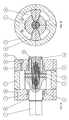
- the hydraulic swing motor selected according to FIGS. 1a and 1b has a shaft 1 and a housing 2.
- the housing 2 is closed at the end sides by housing cover 22, 23.
- the shaft 1 is rotatably mounted in the housing 2.
- the shaft 1 is executed discontinued. It has in the interior of the housing 2 a collar 11. The end faces of the collar 11 slide on the housing covers 22, 23.
- To seal the shaft 1 relative to the housing covers 22, 23 are provided in these sealing grooves 25 for receiving sealing rings.
- To the shaft 1, a wing 12 is formed, which extends to the housing 2 radially outward.
- a double pressure limiting valve 4 which is connected to the connecting channels 14, is arranged in the stepped blind bore 13.
- the stepped blind bore 13 is closed with a cover plate 15a, which is designed as a hollow cylinder with flange.
- a cover plate 15a which is designed as a hollow cylinder with flange.
- About the flange with an indicated lid gland 151 of the end cover 15a is connected to the shaft 1.
- the connections for the supply and removal of the pressure medium as pressure connections 152 are integrated into the end cover 15 b.
- the end cover 15b also has a passage 153 for an electrical supply line 51. This supplies a 4/3-way valve 5, which is arranged in the stepped blind bore 13 of the shaft 1 and connected to the connecting channels 14 and the pressure ports 152.
- connection cover 15c which is designed as a flanged solid cylinder
- multi-path rotary feedthrough 154 penetrates the connection cover 15c flange side orthogonal to the shaft axis.
- rotary feedthrough 154 extends the supply lines 51, which pass on the flange edge of the end cap 15c in sliding contacts 155.
- the sliding contacts 155 are in contact with contacts 62 of a closure cap 6, which are connected to an electrical supply line 63 which is guided on the edge side by the closure cap 6.
- the cap 6 encloses the flange-like end of the end cap 15c of the shaft 1 and is connected via an indicated screw 61 to the housing cover 23.
- the supply and discharge of the pressure medium via orthogonal to the shaft axis in the housing cover 23 introduced pressure ports 29, which penetrate the cover 23 to the shaft 1.
- the pressure ports 29 open into supply channels 16, which are arranged circumferentially on the shaft 1, and are connected via bores with introduced into the end cap 15c channels 156, to which in turn the 4/3-way valve 5 is connected.
- the electric motor 8 is fastened to a lantern 9, which in turn is connected to the shaft 23 surrounding the cover 23 of the housing 2.
- a "ventilation channel" 91 is inserted orthogonal to the shaft axis, which serves to tighten the fastening screws of the coupling 74.
- At the electric motor 8 opposite side of the Reservierpumpe 7 is connected via connecting channels 75, 76 and unlockable check valves 73 with a surge tank 72, in which a piston 71 is arranged.
- the check valves 73 limiting connecting channels 75, 76 are connected via the connecting channels 14 with the working spaces 27 and 28.
- a vent channel 17 of the stepped blind hole 13 to the electric motor 8 opposite end of the shaft 1 is provided.
- the swivel motor does not have a hydraulic pressure connection, since this itself at the same time represents the media container. A supply of the swing motor with pressure medium from the outside is unnecessary, since the sum of the volumes of the working spaces 27, 28 remains constant during a pivoting movement.
Landscapes
- Engineering & Computer Science (AREA)
- Physics & Mathematics (AREA)
- Fluid Mechanics (AREA)
- Mechanical Engineering (AREA)
- General Engineering & Computer Science (AREA)
- Hydraulic Motors (AREA)
- Fluid-Pressure Circuits (AREA)
- Actuator (AREA)
- Valve Device For Special Equipments (AREA)
- Reciprocating, Oscillating Or Vibrating Motors (AREA)
Description
- Die Erfindung betrifft einen Schwenkmotor, vorzugsweise hydraulisch betrieben, der die Merkmale des Oberbegriffs des Patentanspruchs 1 aufweist.
- Schwenkmotore werden in unterschiedlichsten Bereichen der Antriebstechnik eingesetzt. Die nach dem Drehflügelprinzip arbeitenden Motoren setzen den Betriebsdruck eines Druckmediums, wie zum Beispiel Hydrauliköl, direkt und spielfrei in ein Drehmoment bzw. eine Drehbewegung um.
- Ein Schwenkmotor mit den Merkmalen des Oberbegriffs des Anspruchs 1 ist aus DE 197 42 882 C1 bekannt: Der bekannte Schwenkmotor weist ein mit Deckeln versehenes Gehäuse, einen Rotor mit einer in den Deckeln gelagerten Antriebswelle und ein Steuerungssystem auf. In dem Gehäuse ist mindestens eine Rippe (Stator) angeordnet. Die Antriebswelle ist mit Rotorflügeln in gleicher Anzahl wie die Rippen versehen. Die Rippen und Rotorflügel in Verbindung mit dem Gehäuse, der Antriebswelle und den Deckeln bilden Arbeitsräume. Das Steuerungssystem umfasst Druckleitungen (Kanäle), Steuerventile und/oder Reversierpumpen. Über das Steuerungssystem erfolgt eine kontrollierte Zu- und Abführung des Druckmediums. Der Rotorflügel ist innerhalb seines Freiraumes im Gehäuse nur begrenzt schwenkbar und bildet so mit dem Statorflügel des Gehäuses mindestens eine Druck- und eine Ablaufkammer aus. Zur Gewährleistung der inneren Dichtheit zwischen der Druck- und der Ablaufkammer sind der Stator- und der Rotorflügel gegenüber den seitlichen Deckeln und gegenüber der radialen Gehäusewand bzw. der Abtriebswelle mit einem formangepassten Gleichdichtelement ausgerüstet. Die Abdichtung kann auch nur über metallische Spalte erfolgen. Vergleichbare Schwenkmotoren sind noch aus DE 11 79 124 B und aus der im Prioritätsintervall veröffentlichten WO 2004/054823 A1 bekannt.
- Den bekannten Schwenkmotoren gemein ist, dass sie ein erhebliches Bauvolumen des Systems Schwenkmotor/Hydraulikkomponenten aufweisen. Um dieses Bauvolumen zu reduzieren, ist es bekannt, einmal Steuerventile, vgl. DE 1 426 579 A, zum anderen Reversierpumpen innerhalb der Antriebswelle anzuordnen, vgl. DE 100 26 147 A1.
- Der Erfindung liegt die Aufgabe zugrunde, einen Schwenkmotor zu schaffen, bei dem das Bauvolumen des Systems Schwenkmotor/Hydraulikkomponente weiter verringert wird. Gemäß der Erfindung wird diese Aufgabe dadurch gelöst, dass die Antriebswelle mindestens eine Stufen-Sackbohrung zur Aufnahme von Steuer- und Regelkomponenten aufweist, von welcher mindestens ein Verbindungskanal in die Arbeitsräume abzweigt, und dass die Steuerventile und/oder die Reversierpumpe innerhalb der Antriebswelle angeordnet sind.
- Mit der Erfindung ist ein Schwenkmotor geschaffen, bei dem das Bauvolumen des Systems Schwenkmotor/Hydraulikkomponenten deutlich verringert ist. Die aus DE 197 54 539 A1 bekannte Maßnahme, - nur - das Schaltventil zur Stabilitätskontrolle in dem Hohlraum der Motorwelle unterzubringen wird bei der Erfindung konsequent auf alle, jedenfalls auf die wesentlichen Steuer- und Regelkomponenten, ausgedehnt, über die das kontrollierte Zu- und Abführen des Druckmediums erfolgt. Durch die Möglichkeit der Integration von Bauteilen in die Stufen-Sackbohrung der Antriebswelle lässt sich externes Bauvolumen reduzieren. Gleichzeitig wird die Welle nur unwesentlich bezüglich des übertragbaren Drehmoments geschwächt.
- Dadurch, dass die Steuerventile des Systems innerhalb der Antriebswelle angeordnet sind, wird das Ansprechverhalten von Druckventilen, die zur Überdruckabsicherung des Schwenkmotors dienen, zeitlich verkürzt. Aufgrund der kurzen internen Längen der Verbindungskanäle erreicht eine Druckwelle schneller das Druckventil und muss sich nicht durch Rohrleitungen und Schläuche fortpflanzen, was ein verzögertes Ansprechverhalten zur Folge hat und zu schädlichen Druckspitzen im Schwenkmotor führen kann. Weiterhin wird durch die Integration der Hydraulikkomponenten eine Erhöhung der hydraulischen Steifigkeit erzielt. Das eingeschlossene Volumen des Druckmediums, bestehend aus dem Volumen der Arbeitsräume des Schwenkmotors (Schluckvolumen) und dem Volumen der Verbindungskanäle bis zur Komponente (Totvolumen), ist reduziert. Durch die daraus resultierende verringerte Kompressibilität wird die Steifigkeit des Systems erhöht, was sich positiv auf das Regelungsverhalten des Systems auswirkt.
- Darüber hinaus führt die Integration der Steuerventile in die Welle zu einer Optimierung des thermischen Systemverhaltens. Durch das verringerte Totvolumen zu einer Komponente, zum Beispiel einem Wegeventil oder Servoventil, wird der Austausch des Druckmediums der Arbeitsräume (Schluckvolumen) gegen das Druckmedium des Tankvolumens des Versorgungsaggregats optimiert. Gerade bei kleinen Arbeitsschwenkwinkeln und großem Totvolumen, dass heißt langen Leitungen von den Arbeitsräumen bis zum Wegeventil, erwärmt sich das Druckmedium im Schwenkmotor stark, da es aufgrund der pendelnden Ölsäulen in den Leitungen nicht gegen kühleres Druckmedium aus dem Tank des Versorgungsaggregats getauscht wird. Die interne Anordnung ermöglicht ein größtmögliches Austauschvolumen.
- In weiterer Ausbildung der Erfindung sind sowohl die Steuerventile als auch die Reversierpumpe innerhalb der Antriebswelle angeordnet, wobei an das bohrungsseitige Wellenende ein Elektromotor angeordnet ist, der die Reversierpumpe antreibt. Durch die Integration sowohl der Steuerventile als auch der Reversierpumpe in die Antriebswelle des Schwenkmotors sowie der Adaption eines Elektromotors am Schwenkmotor entfällt das komplette Versorgungsaggregat inklusive der Verrohrung, was zu einer deutlichen Reduzierung der Komponentenanzahl führt. Es wird kein separater Medienbehälter mehr benötigt, da die Summe der Volumina der Arbeitsräume bei einer Schwenkbewegung konstant bleibt und somit der Schwenkmotor zugleich den Medienbehälter darstellt. Weiter entfällt ein zur Schwenkrichtungsumkehr benötigtes Wegeventil, da die Richtungsumkehr über die integrierte Reversierpumpe mittels Drehrichtungsänderung des E-Motors vorgenommen wird.
- In Weiterbildung der Erfindung ist ein Ausgleichsbehälter in die Welle integriert. Dieser dient dem Ausgleich von geringeren Leckagen sowie temperatur- und druckbedingten Volumenänderungen.
- In weiterer Ausgestaltung der Erfindung sind zwischen den Arbeitsräumen und dem Ausgleichsbehälter entsperrbare Rückschlagventile angeordnet. Hierdurch wird ein kontrollierter Ein- und Austritt des Differenzvolumens zwischen den Arbeitsräumen und dem Ausgleichsbehälter ermöglicht.
- Andere Weiterbildungen und Ausgestaltungen der Erfindung sind in den übrigen Unteransprüchen angegeben. Ausführungsbeispiele der Erfindung sind in den Zeichnungen dargestellt und werden nachfolgend im Einzelnen beschrieben. Es zeigen:
- Figur 1a
- einen Schwenkmotor mit Stufen-Sackbohrung in der Welle im Längsschnitt;
- Figur 1b
- den Schwenkmotor aus Figur 1a im Querschnitt;
- Figur 2a
- einen Schwenkmotor mit integriertem Doppel-Druckbegrenzungsventil im Längsschnitt;
- Figur 2b
- den Schwenkmotor aus Figur 2a im Querschnitt;
- Figur 3a
- einen Schwenkmotor mit integriertem 4/3-Wegeventil im Längsschnitt;
- Figur 3b
- den Schwenkmotor aus Figur 3a im Querschnitt;
- Figur 4a
- einen Schwenkmotor mit integriertem 4/3-Wegeventil und Drehdurchführung im Längsschnitt;
- Figur 4b
- den Schwenkmotor aus Figur 4a im Querschnitt;
- Figur 5a
- einen Schwenkmotor mit integrierter Reversierpumpe im Längsschnitt und entsperrbaren Rückschlagventilen;
- Figur 5b
- den Schwenkmotor aus Figur 5a im Querschnitt.
- Der als Ausführungsbeispiel gewählte hydraulische Schwenkmotor gemäß Figuren 1a und 1b weist eine Welle 1 und ein Gehäuse 2 auf. Das Gehäuse 2 ist an den Stirnseiten durch Gehäusedeckel 22, 23 verschlossen. Eine Deckelverschraubung 24, mit deren Hilfe die Gehäusedeckel 22, 23 an dem Gehäuse 2 befestigt sind, ist angedeutet.
- Mit Hilfe von Lagern 3, die in den Gehäusedeckeln 22, 23 angeordnet sind, ist die Welle 1 in dem Gehäuse 2 drehbar gelagert. Die Welle 1 ist abgesetzt ausgeführt. Sie weist im Innern des Gehäuses 2 einen Bund 11 auf. Die Stirnseiten des Bundes 11 gleiten an den Gehäusedeckeln 22, 23. Zur Abdichtung der Welle 1 gegenüber den Gehäusedeckeln 22, 23 sind in diesen Dichtungsnuten 25 zur Aufnahme von Dichtungsringen vorgesehen. An die Welle 1 ist ein Flügel 12 angeformt, der bis zum Gehäuse 2 radial nach außen reicht.
- An das Gehäuse 2 ist eine nach innen bis zu dem Bund 11 reichende Rippe 21 angeformt. In den Gehäusedeckel 23 sind Druckanschlüsse 26 für die Zu- und Abführung des Druckmediums in die bzw. aus Arbeitsräumen 27, 28 eingebracht, die zwischen den Flügeln 12 und den Rippen 21 gebildet sind. Rotationssymmetrisch zur Wellenachse ist in die Welle 2 eine Stufen-Sackbohrung 13 eingebracht, von der Verbindungskanäle 14 in die Arbeitsräume 27, 28 verlaufen.
- Im Ausführungsbeispiel nach den Figuren 2a und 2b ist in der Stufen-Sackbohrung 13 ein Doppel-Druckbegrenzungsventil 4 angeordnet, das an die Verbindungskanäle 14 angeschlossen ist. Die Stufen-Sackbohrung 13 ist mit einem Abschlussdeckel 15a verschlossen, der als Hohlzylinder mit Anschlussflansch ausgeführt ist. Über den Flansch mit einer angedeuteten Deckelverschraubung 151 ist der Abschlussdeckel 15a mit der Welle 1 verbunden.
- Im Ausführungsbeispiel nach den Figuren 3a und 3b sind die Anschlüsse für die Zu- und Abführung des Druckmediums als Druckanschlüsse 152 in den Abschlussdeckel 15b integriert. Der Abschlussdeckel 15b weist ferner eine Durchführung 153 für eine elektrische Versorgungsleitung 51 auf. Diese versorgt ein 4/3-Wegeventil 5, welches in der Stufen-Sackbohrung 13 der Welle 1 angeordnet und an die Verbindungskanäle 14 sowie die Druckanschlüsse 152 angeschlossen ist.
- Im Ausführungsbeispiel nach Figuren 4a und 4b erfolgt die elektrische Versorgung des 4/3-Wegeventils 5 über eine in den Anschlussdeckel 15c, der als mit Flansch versehener Vollzylinder ausgeführt ist, eingebrachte mehrpfadige Drehdurchführung 154. Letzter durchdringt den Anschlussdeckel 15c flanschseitig orthogonal zur Wellenachse. Durch die Drehdurchführung 154 verlaufen die Versorgungsleitungen 51, die am flanschartigen Rand des Abschlussdeckels 15c in Schleifkontakte 155 übergehen. Die Schleifkontakte 155 stehen mit Kontakten 62 einer Verschlusskappe 6 in Berührung, welche an eine elektrische Versorgungsleitung 63 angeschlossen sind, die randseitig durch die Verschlusskappe 6 geführt ist. Die Verschlusskappe 6 umschließt das flanschartige Ende des Abschlussdeckels 15c der Welle 1 und ist über eine angedeutete Verschraubung 61 mit dem Gehäusedeckel 23 verbunden.
- Die Zu- und Abführung des Druckmediums erfolgt über orthogonal zur Wellenachse in den Gehäusedeckel 23 eingebrachte Druckanschlüsse 29, welche den Deckel 23 bis zur Welle 1 durchdringen. Die Druckanschlüsse 29 münden in Versorgungskanäle 16, welche auf der Welle 1 umlaufend angeordnet sind, und über Bohrungen mit in den Abschlussdeckel 15c eingebrachten Kanälen 156 verbunden sind, an denen wiederum das 4/3-Wegeventil 5 angeschlossen ist.
- Im Ausführungsbeispiel nach den Figuren 5a und 5b ist in der Stufen-Sackbohrung 13 der Welle 1 eine Reversierpumpe 7 angeordnet, die über eine Kupplung 74 durch einen Elektromotor 8 angetrieben wird. Der Elektromotor 8 ist an einer Laterne 9 befestigt, welche wiederum die Welle 1 umschließend mit dem Deckel 23 des Gehäuses 2 verbunden ist. In der Laterne 9 ist orthogonal zur Wellenachse ein "Lüftungskanal" 91 eingebracht, der zum Anziehen der Befestigungsschrauben der Kupplung 74 dient. An der dem Elektromotor 8 entgegengerichteten Seite ist die Reservierpumpe 7 über Verbindungskanäle 75, 76 sowie entsperrbare Rückschlagventile 73 mit einem Ausgleichsbehälter 72 verbunden, in dem ein Kolben 71 angeordnet ist. Die die Rückschlagventile 73 begrenzenden Verbindungskanäle 75, 76 sind über die Verbindungskanäle 14 mit den Arbeitsräumen 27 und 28 verbunden. Zur Entlüftung der Anordnung ist entlang der Mittelachse der Welle 1 ein Entlüftungskanal 17 von der Stufen-Sackbohrung 13 bis zu dem Elektromotor 8 gegenüberliegenden Ende der Welle 1 vorgesehen.
- Der Schwenkmotor weist keinen hydraulischen Druckanschluss aus, da dieser selbst zugleich den Medienbehälter darstellt. Eine Versorgung des Schwenkmotors mit Druckmedium von außen erübrigt sich, da die Summe der Volumina der Arbeitsräumen 27, 28 bei einer Schwenkbewegung konstant bleibt.
Claims (11)
- Schwenkmotor, vorzugsweise hydraulisch betrieben, der ein mit Deckeln (22, 23) versehenes Gehäuse (2), in dem ein Stator mit mindestens einer Rippe (21) angeordnet ist, einen Rotor mit einer in den Deckeln gelagerten Antriebswelle (1), die abschnittsweise hohl ausgeführt und mit Rotorflügeln (12) in gleicher Anzahl wie die Rippen (21) versehen ist, wobei die Rippen (21) und Rotorflügel (12) in Verbindung mit dem Gehäuse (2), der Antriebswelle (1) und den Deckeln (22, 23) Arbeitsräume bilden, und der ein Steuerungssystem aus Druckleitungen, Steuerventilen und Reversierpumpe (7) aufweist, über das eine kontrollierte Zu- und Abführung eines Druckmediums erfolgt, wobei die Antriebswelle (1) mindestens eine Stufen-Sackbohrung (13) zur Aufnahme von Steuer- und Regelkomponenten aufweist, von welcher mindestens ein Verbindungskanal (14) in die Arbeitsräume (27, 28) abzweigt, dadurch gekennzeichnet, dass die Steuerventile und/oder die Reversierpumpe (7) innerhalb der Antriebswelle (1) angeordnet sind.
- Schwenkmotor nach Anspruch 1, dadurch gekennzeichnet, dass sowohl die Steuerventile als auch die Reversierpumpe (7) innerhalb der Antriebswelle (1) angeordnet sind.
- Schwenkmotor nach Anspruch 1 oder 2, dadurch gekennzeichnet, dass die Antriebswelle (1) bohrungsseitig mit einem Abschlussdeckel (15) verschlossen ist, der Druck- (152) und/oder elektrische Anschlüsse (153, 154) aufweist, und über den die Versorgung mit Druckmedium und/oder elektrischer Energie erfolgt.
- Schwenkmotor nach Anspruch 2 oder 3, dadurch gekennzeichnet, dass die Stufen-Sackbohrung (13) mit einem Entlüftungskanal (17) versehen ist.
- Schwenkmotor nach einem der Ansprüche 1 bis 4, dadurch gekennzeichnet, dass an das bohrungsseitige Ende der Welle (1) ein Elektromotor (8) angeordnet ist, der die Reversierpumpe (7) antreibt.
- Schwenkmotor nach einem der Ansprüche 1 bis 5, dadurch gekennzeichnet, dass in der Stufen-Sackbohrung (13) der Welle (1) ein Ausgleichsbehälter (72) angeordnet ist.
- Schwenkmotor nach Anspruch 6, dadurch gekennzeichnet, dass zwischen den Arbeitsräumen (27, 28) und dem Ausgleichsbehälter (72) entsperrbare Rückschlagventile (73) angeordnet sind.
- Schwenkmotor nach einem der Ansprüche 1 bis 7, dadurch gekennzeichnet, dass radial in der Welle (1) ein Druckbegrenzungsventil (4) angeordnet ist.
- Schwenkmotor nach Anspruch 8, dadurch gekennzeichnet, dass das Druckbegrenzungsventil (4) in einem der Gehäusedeckel (22, 23) angeordnet ist.
- Schwenkmotor nach einem der Ansprüche 1 bis 9, dadurch gekennzeichnet, dass in der Welle (1) eine Drehdurchführung (154) angeordnet ist und die elektrische Versorgung von in der Antriebswelle (1) integrierten Bauteilen über Schleifkontakte (155) erfolgt, die in einem die Stufen-Sackbohrung (13) verschließenden Abschlussdeckel (15) angeordnet sind.
- Schwenkmotor nach einem der Ansprüche 1 bis 10, dadurch gekennzeichnet, dass bohrungsseitig in die Welle (1) Versorgungsnuten (16) eingebracht sind, die mit in dem Gehäusedeckel (23) eingebrachten Druckanschlüsse (29) korrespondieren.
Applications Claiming Priority (2)
| Application Number | Priority Date | Filing Date | Title |
|---|---|---|---|
| DE10320456 | 2003-05-08 | ||
| DE10320456A DE10320456B4 (de) | 2003-05-08 | 2003-05-08 | Schwenkmotor |
Publications (3)
| Publication Number | Publication Date |
|---|---|
| EP1475543A2 EP1475543A2 (de) | 2004-11-10 |
| EP1475543A3 EP1475543A3 (de) | 2004-12-15 |
| EP1475543B1 true EP1475543B1 (de) | 2006-05-17 |
Family
ID=32981270
Family Applications (1)
| Application Number | Title | Priority Date | Filing Date |
|---|---|---|---|
| EP04008277A Expired - Lifetime EP1475543B1 (de) | 2003-05-08 | 2004-04-06 | Schwenkmotor |
Country Status (3)
| Country | Link |
|---|---|
| EP (1) | EP1475543B1 (de) |
| AT (1) | ATE326639T1 (de) |
| DE (2) | DE10320456B4 (de) |
Families Citing this family (10)
| Publication number | Priority date | Publication date | Assignee | Title |
|---|---|---|---|---|
| DE102007005839A1 (de) * | 2007-02-01 | 2008-08-07 | Zf Friedrichshafen Ag | Druckmittel betätigtes Aggregat |
| DE102007009592A1 (de) * | 2007-02-26 | 2008-08-28 | Zf Friedrichshafen Ag | Aggregat, insbesondere Schwenkmotor |
| DE102008008508A1 (de) * | 2007-04-20 | 2008-10-23 | Zf Friedrichshafen Ag | Torsionsschwingungsdämpfer für den Antriebsstrang eines Fahrzeugs |
| IT1398128B1 (it) * | 2009-03-27 | 2013-02-14 | Rovel S R L | Attuatore azionato da un fluido in pressione |
| CN102926923B (zh) * | 2011-06-02 | 2015-04-08 | 张家港圣美意机械有限公司 | 液压马达 |
| CN102230447B (zh) * | 2011-06-02 | 2013-02-06 | 张家港圣美意机械有限公司 | 液压马达 |
| CN102926924B (zh) * | 2011-06-02 | 2015-04-08 | 张家港圣美意机械有限公司 | 液压马达 |
| CN104564512B (zh) * | 2014-12-19 | 2016-08-24 | 合肥创源车辆控制技术有限公司 | 一种液力马达 |
| AT16161U1 (de) * | 2016-07-21 | 2019-03-15 | Pimatic Oy | Oszillationsaktuator |
| DE102018205638B4 (de) * | 2018-04-13 | 2024-06-13 | Festo Se & Co. Kg | Drehantriebsvorrichtung und damit ausgestatteter Roboterarm eines Roboters |
Family Cites Families (7)
| Publication number | Priority date | Publication date | Assignee | Title |
|---|---|---|---|---|
| DE1179124B (de) * | 1960-12-20 | 1964-10-01 | Daimler Benz Ag | Vorrichtung zur Kurvenstabilisierung des Wagenkastens bei Kraftfahrzeugen |
| GB1071621A (en) * | 1963-01-16 | 1967-06-07 | Sperry Gyroscope Co Ltd | Rotary hydraulic actuators and hydraulically actuated valves |
| DE3730045A1 (de) * | 1987-09-08 | 1989-03-16 | Blohm Voss Ag | Mit druckmittel betriebener schwenkfluegelmotor |
| DE19742882C1 (de) * | 1997-09-29 | 1999-01-07 | Pnp Luftfedersysteme Gmbh | Radialer Schwenkmotor |
| DE19754539C2 (de) * | 1997-12-09 | 2001-11-29 | Mannesmann Sachs Ag | Schwenkmotor |
| DE10026147C2 (de) * | 2000-05-26 | 2002-04-18 | Emg Eltma Hebezeuge Oschersleb | Elektrohydraulisches Betätigungsgerät |
| DE10259264B4 (de) * | 2002-12-17 | 2004-12-02 | Thyssenkrupp Automotive Ag | Schwenkmotor |
-
2003
- 2003-05-08 DE DE10320456A patent/DE10320456B4/de not_active Expired - Fee Related
-
2004
- 2004-04-06 DE DE502004000565T patent/DE502004000565D1/de not_active Expired - Lifetime
- 2004-04-06 EP EP04008277A patent/EP1475543B1/de not_active Expired - Lifetime
- 2004-04-06 AT AT04008277T patent/ATE326639T1/de not_active IP Right Cessation
Also Published As
| Publication number | Publication date |
|---|---|
| DE502004000565D1 (de) | 2006-06-22 |
| DE10320456B4 (de) | 2005-10-06 |
| ATE326639T1 (de) | 2006-06-15 |
| DE10320456A1 (de) | 2004-12-02 |
| EP1475543A3 (de) | 2004-12-15 |
| EP1475543A2 (de) | 2004-11-10 |
Similar Documents
| Publication | Publication Date | Title |
|---|---|---|
| EP2732164B1 (de) | Zahnringpumpe | |
| EP1837530B1 (de) | Betätigungsvorrichtung | |
| EP1475543B1 (de) | Schwenkmotor | |
| EP1687201B1 (de) | Strahlantrieb | |
| DE102005056909A1 (de) | Hydraulische Zahnradmaschine | |
| DE102008030058A1 (de) | Nockenwellenverstelleinrichtung und geeignetes Ventil dafür | |
| DE1553275A1 (de) | Hydraulische Vorrichtung | |
| DE102007004187B4 (de) | Regelbare Kühlmittelpumpe | |
| WO2012034619A1 (de) | Axialkolbenmaschine | |
| DE2304453C3 (de) | Hydrostatisches Getriebe zum Fahrantrieb eines Kraftfahrzeugs | |
| DE2017595A1 (de) | ||
| DE102015213338B4 (de) | Aktuatoreinheit | |
| EP1495227B1 (de) | Hydraulisches pumpenaggregat | |
| DE102008060596A1 (de) | Hydrotransformator | |
| DE20307106U1 (de) | Schwenkmotor | |
| DE102015115841A1 (de) | Pumpen-Motor-Einheit mit einer Kühlung eines die Pumpe antreibenden Elektromotors mittels Leckagefluid | |
| DE1528367A1 (de) | Hydraulische Pumpen- und Motorvorrichtung | |
| DE102009037260B4 (de) | Vorrichtung zur Veränderung der relativen Winkellage einer Nockenwelle gegenüber einer Kurbelwelle einer Brennkraftmaschine | |
| EP1026401B1 (de) | Hydrostatische Pumpe | |
| WO2016016310A1 (de) | Hydraulische achse | |
| EP1081382B1 (de) | Zahnradmaschine | |
| EP3737862A1 (de) | Hydromaschine, hydraulisches aggregat mit der hydromaschine, und hydraulische achse mit der hydromaschine | |
| DE102012213985A1 (de) | Pumpeneinrichtung | |
| WO2004027267A1 (de) | Hydrotransformator | |
| DE19637419C1 (de) | Hydropumpe und Hydromotor |
Legal Events
| Date | Code | Title | Description |
|---|---|---|---|
| PUAI | Public reference made under article 153(3) epc to a published international application that has entered the european phase |
Free format text: ORIGINAL CODE: 0009012 |
|
| PUAL | Search report despatched |
Free format text: ORIGINAL CODE: 0009013 |
|
| AK | Designated contracting states |
Kind code of ref document: A2 Designated state(s): AT BE BG CH CY CZ DE DK EE ES FI FR GB GR HU IE IT LI LU MC NL PL PT RO SE SI SK TR |
|
| AX | Request for extension of the european patent |
Extension state: AL HR LT LV MK |
|
| AK | Designated contracting states |
Kind code of ref document: A3 Designated state(s): AT BE BG CH CY CZ DE DK EE ES FI FR GB GR HU IE IT LI LU MC NL PL PT RO SE SI SK TR |
|
| AX | Request for extension of the european patent |
Extension state: AL HR LT LV MK |
|
| 17P | Request for examination filed |
Effective date: 20050607 |
|
| AKX | Designation fees paid |
Designated state(s): AT BE BG CH CY CZ DE DK EE ES FI FR GB GR HU IE IT LI LU MC NL PL PT RO SE SI SK TR |
|
| GRAP | Despatch of communication of intention to grant a patent |
Free format text: ORIGINAL CODE: EPIDOSNIGR1 |
|
| GRAS | Grant fee paid |
Free format text: ORIGINAL CODE: EPIDOSNIGR3 |
|
| GRAA | (expected) grant |
Free format text: ORIGINAL CODE: 0009210 |
|
| AK | Designated contracting states |
Kind code of ref document: B1 Designated state(s): AT BE BG CH CY CZ DE DK EE ES FI FR GB GR HU IE IT LI LU MC NL PL PT RO SE SI SK TR |
|
| PG25 | Lapsed in a contracting state [announced via postgrant information from national office to epo] |
Ref country code: IT Free format text: LAPSE BECAUSE OF FAILURE TO SUBMIT A TRANSLATION OF THE DESCRIPTION OR TO PAY THE FEE WITHIN THE PRESCRIBED TIME-LIMIT;WARNING: LAPSES OF ITALIAN PATENTS WITH EFFECTIVE DATE BEFORE 2007 MAY HAVE OCCURRED AT ANY TIME BEFORE 2007. THE CORRECT EFFECTIVE DATE MAY BE DIFFERENT FROM THE ONE RECORDED. Effective date: 20060517 Ref country code: CZ Free format text: LAPSE BECAUSE OF FAILURE TO SUBMIT A TRANSLATION OF THE DESCRIPTION OR TO PAY THE FEE WITHIN THE PRESCRIBED TIME-LIMIT Effective date: 20060517 Ref country code: NL Free format text: LAPSE BECAUSE OF FAILURE TO SUBMIT A TRANSLATION OF THE DESCRIPTION OR TO PAY THE FEE WITHIN THE PRESCRIBED TIME-LIMIT Effective date: 20060517 Ref country code: FI Free format text: LAPSE BECAUSE OF FAILURE TO SUBMIT A TRANSLATION OF THE DESCRIPTION OR TO PAY THE FEE WITHIN THE PRESCRIBED TIME-LIMIT Effective date: 20060517 Ref country code: SK Free format text: LAPSE BECAUSE OF FAILURE TO SUBMIT A TRANSLATION OF THE DESCRIPTION OR TO PAY THE FEE WITHIN THE PRESCRIBED TIME-LIMIT Effective date: 20060517 Ref country code: SI Free format text: LAPSE BECAUSE OF FAILURE TO SUBMIT A TRANSLATION OF THE DESCRIPTION OR TO PAY THE FEE WITHIN THE PRESCRIBED TIME-LIMIT Effective date: 20060517 Ref country code: RO Free format text: LAPSE BECAUSE OF FAILURE TO SUBMIT A TRANSLATION OF THE DESCRIPTION OR TO PAY THE FEE WITHIN THE PRESCRIBED TIME-LIMIT Effective date: 20060517 Ref country code: PL Free format text: LAPSE BECAUSE OF FAILURE TO SUBMIT A TRANSLATION OF THE DESCRIPTION OR TO PAY THE FEE WITHIN THE PRESCRIBED TIME-LIMIT Effective date: 20060517 Ref country code: IE Free format text: LAPSE BECAUSE OF FAILURE TO SUBMIT A TRANSLATION OF THE DESCRIPTION OR TO PAY THE FEE WITHIN THE PRESCRIBED TIME-LIMIT Effective date: 20060517 Ref country code: GB Free format text: LAPSE BECAUSE OF FAILURE TO SUBMIT A TRANSLATION OF THE DESCRIPTION OR TO PAY THE FEE WITHIN THE PRESCRIBED TIME-LIMIT Effective date: 20060517 |
|
| REG | Reference to a national code |
Ref country code: GB Ref legal event code: FG4D Free format text: NOT ENGLISH |
|
| REG | Reference to a national code |
Ref country code: CH Ref legal event code: EP |
|
| REG | Reference to a national code |
Ref country code: IE Ref legal event code: FG4D Free format text: LANGUAGE OF EP DOCUMENT: GERMAN |
|
| REF | Corresponds to: |
Ref document number: 502004000565 Country of ref document: DE Date of ref document: 20060622 Kind code of ref document: P |
|
| PG25 | Lapsed in a contracting state [announced via postgrant information from national office to epo] |
Ref country code: SE Free format text: LAPSE BECAUSE OF FAILURE TO SUBMIT A TRANSLATION OF THE DESCRIPTION OR TO PAY THE FEE WITHIN THE PRESCRIBED TIME-LIMIT Effective date: 20060817 Ref country code: DK Free format text: LAPSE BECAUSE OF FAILURE TO SUBMIT A TRANSLATION OF THE DESCRIPTION OR TO PAY THE FEE WITHIN THE PRESCRIBED TIME-LIMIT Effective date: 20060817 |
|
| PG25 | Lapsed in a contracting state [announced via postgrant information from national office to epo] |
Ref country code: ES Free format text: LAPSE BECAUSE OF FAILURE TO SUBMIT A TRANSLATION OF THE DESCRIPTION OR TO PAY THE FEE WITHIN THE PRESCRIBED TIME-LIMIT Effective date: 20060828 |
|
| PG25 | Lapsed in a contracting state [announced via postgrant information from national office to epo] |
Ref country code: PT Free format text: LAPSE BECAUSE OF FAILURE TO SUBMIT A TRANSLATION OF THE DESCRIPTION OR TO PAY THE FEE WITHIN THE PRESCRIBED TIME-LIMIT Effective date: 20061017 |
|
| NLV1 | Nl: lapsed or annulled due to failure to fulfill the requirements of art. 29p and 29m of the patents act | ||
| GBV | Gb: ep patent (uk) treated as always having been void in accordance with gb section 77(7)/1977 [no translation filed] |
Effective date: 20060517 |
|
| REG | Reference to a national code |
Ref country code: IE Ref legal event code: FD4D |
|
| PLBE | No opposition filed within time limit |
Free format text: ORIGINAL CODE: 0009261 |
|
| STAA | Information on the status of an ep patent application or granted ep patent |
Free format text: STATUS: NO OPPOSITION FILED WITHIN TIME LIMIT |
|
| 26N | No opposition filed |
Effective date: 20070220 |
|
| EN | Fr: translation not filed | ||
| BERE | Be: lapsed |
Owner name: HENSE SYSTEMTECHNIK G.M.B.H. & CO. KG Effective date: 20070430 |
|
| PG25 | Lapsed in a contracting state [announced via postgrant information from national office to epo] |
Ref country code: BE Free format text: LAPSE BECAUSE OF NON-PAYMENT OF DUE FEES Effective date: 20070430 |
|
| PG25 | Lapsed in a contracting state [announced via postgrant information from national office to epo] |
Ref country code: FR Free format text: LAPSE BECAUSE OF FAILURE TO SUBMIT A TRANSLATION OF THE DESCRIPTION OR TO PAY THE FEE WITHIN THE PRESCRIBED TIME-LIMIT Effective date: 20070309 Ref country code: GR Free format text: LAPSE BECAUSE OF FAILURE TO SUBMIT A TRANSLATION OF THE DESCRIPTION OR TO PAY THE FEE WITHIN THE PRESCRIBED TIME-LIMIT Effective date: 20060818 |
|
| PG25 | Lapsed in a contracting state [announced via postgrant information from national office to epo] |
Ref country code: BG Free format text: LAPSE BECAUSE OF FAILURE TO SUBMIT A TRANSLATION OF THE DESCRIPTION OR TO PAY THE FEE WITHIN THE PRESCRIBED TIME-LIMIT Effective date: 20060817 |
|
| PG25 | Lapsed in a contracting state [announced via postgrant information from national office to epo] |
Ref country code: EE Free format text: LAPSE BECAUSE OF FAILURE TO SUBMIT A TRANSLATION OF THE DESCRIPTION OR TO PAY THE FEE WITHIN THE PRESCRIBED TIME-LIMIT Effective date: 20060517 |
|
| PG25 | Lapsed in a contracting state [announced via postgrant information from national office to epo] |
Ref country code: AT Free format text: LAPSE BECAUSE OF NON-PAYMENT OF DUE FEES Effective date: 20070406 |
|
| PG25 | Lapsed in a contracting state [announced via postgrant information from national office to epo] |
Ref country code: FR Free format text: LAPSE BECAUSE OF FAILURE TO SUBMIT A TRANSLATION OF THE DESCRIPTION OR TO PAY THE FEE WITHIN THE PRESCRIBED TIME-LIMIT Effective date: 20060517 |
|
| REG | Reference to a national code |
Ref country code: CH Ref legal event code: PL |
|
| PG25 | Lapsed in a contracting state [announced via postgrant information from national office to epo] |
Ref country code: CH Free format text: LAPSE BECAUSE OF NON-PAYMENT OF DUE FEES Effective date: 20080430 Ref country code: LI Free format text: LAPSE BECAUSE OF NON-PAYMENT OF DUE FEES Effective date: 20080430 |
|
| PG25 | Lapsed in a contracting state [announced via postgrant information from national office to epo] |
Ref country code: MC Free format text: LAPSE BECAUSE OF NON-PAYMENT OF DUE FEES Effective date: 20070430 |
|
| PG25 | Lapsed in a contracting state [announced via postgrant information from national office to epo] |
Ref country code: LU Free format text: LAPSE BECAUSE OF NON-PAYMENT OF DUE FEES Effective date: 20070406 Ref country code: CY Free format text: LAPSE BECAUSE OF FAILURE TO SUBMIT A TRANSLATION OF THE DESCRIPTION OR TO PAY THE FEE WITHIN THE PRESCRIBED TIME-LIMIT Effective date: 20060517 |
|
| PG25 | Lapsed in a contracting state [announced via postgrant information from national office to epo] |
Ref country code: HU Free format text: LAPSE BECAUSE OF FAILURE TO SUBMIT A TRANSLATION OF THE DESCRIPTION OR TO PAY THE FEE WITHIN THE PRESCRIBED TIME-LIMIT Effective date: 20061118 Ref country code: TR Free format text: LAPSE BECAUSE OF FAILURE TO SUBMIT A TRANSLATION OF THE DESCRIPTION OR TO PAY THE FEE WITHIN THE PRESCRIBED TIME-LIMIT Effective date: 20060517 |
|
| REG | Reference to a national code |
Representative=s name: PATENTANWAELTE BALS & VOGEL, DE Ref country code: DE Ref legal event code: R082 Ref document number: 502004000565 Country of ref document: DE |
|
| PGFP | Annual fee paid to national office [announced via postgrant information from national office to epo] |
Ref country code: DE Payment date: 20170321 Year of fee payment: 14 |
|
| REG | Reference to a national code |
Ref country code: DE Ref legal event code: R119 Ref document number: 502004000565 Country of ref document: DE |
|
| PG25 | Lapsed in a contracting state [announced via postgrant information from national office to epo] |
Ref country code: DE Free format text: LAPSE BECAUSE OF NON-PAYMENT OF DUE FEES Effective date: 20181101 |