EP1475525A2 - Winkelsensor für eine elektronische Drosselklappe und Verfahren zur Herstellung dieses Winkelsensors - Google Patents
Winkelsensor für eine elektronische Drosselklappe und Verfahren zur Herstellung dieses Winkelsensors Download PDFInfo
- Publication number
- EP1475525A2 EP1475525A2 EP04010818A EP04010818A EP1475525A2 EP 1475525 A2 EP1475525 A2 EP 1475525A2 EP 04010818 A EP04010818 A EP 04010818A EP 04010818 A EP04010818 A EP 04010818A EP 1475525 A2 EP1475525 A2 EP 1475525A2
- Authority
- EP
- European Patent Office
- Prior art keywords
- throttle valve
- magnet
- valve shaft
- magnetic
- circuitry
- Prior art date
- Legal status (The legal status is an assumption and is not a legal conclusion. Google has not performed a legal analysis and makes no representation as to the accuracy of the status listed.)
- Withdrawn
Links
Images


Classifications
-
- G—PHYSICS
- G01—MEASURING; TESTING
- G01D—MEASURING NOT SPECIALLY ADAPTED FOR A SPECIFIC VARIABLE; ARRANGEMENTS FOR MEASURING TWO OR MORE VARIABLES NOT COVERED IN A SINGLE OTHER SUBCLASS; TARIFF METERING APPARATUS; MEASURING OR TESTING NOT OTHERWISE PROVIDED FOR
- G01D5/00—Mechanical means for transferring the output of a sensing member; Means for converting the output of a sensing member to another variable where the form or nature of the sensing member does not constrain the means for converting; Transducers not specially adapted for a specific variable
- G01D5/12—Mechanical means for transferring the output of a sensing member; Means for converting the output of a sensing member to another variable where the form or nature of the sensing member does not constrain the means for converting; Transducers not specially adapted for a specific variable using electric or magnetic means
- G01D5/14—Mechanical means for transferring the output of a sensing member; Means for converting the output of a sensing member to another variable where the form or nature of the sensing member does not constrain the means for converting; Transducers not specially adapted for a specific variable using electric or magnetic means influencing the magnitude of a current or voltage
- G01D5/142—Mechanical means for transferring the output of a sensing member; Means for converting the output of a sensing member to another variable where the form or nature of the sensing member does not constrain the means for converting; Transducers not specially adapted for a specific variable using electric or magnetic means influencing the magnitude of a current or voltage using Hall-effect devices
- G01D5/145—Mechanical means for transferring the output of a sensing member; Means for converting the output of a sensing member to another variable where the form or nature of the sensing member does not constrain the means for converting; Transducers not specially adapted for a specific variable using electric or magnetic means influencing the magnitude of a current or voltage using Hall-effect devices influenced by the relative movement between the Hall device and magnetic fields
-
- F—MECHANICAL ENGINEERING; LIGHTING; HEATING; WEAPONS; BLASTING
- F02—COMBUSTION ENGINES; HOT-GAS OR COMBUSTION-PRODUCT ENGINE PLANTS
- F02D—CONTROLLING COMBUSTION ENGINES
- F02D11/00—Arrangements for, or adaptations to, non-automatic engine control initiation means, e.g. operator initiated
- F02D11/06—Arrangements for, or adaptations to, non-automatic engine control initiation means, e.g. operator initiated characterised by non-mechanical control linkages, e.g. fluid control linkages or by control linkages with power drive or assistance
- F02D11/10—Arrangements for, or adaptations to, non-automatic engine control initiation means, e.g. operator initiated characterised by non-mechanical control linkages, e.g. fluid control linkages or by control linkages with power drive or assistance of the electric type
- F02D11/106—Detection of demand or actuation
-
- F—MECHANICAL ENGINEERING; LIGHTING; HEATING; WEAPONS; BLASTING
- F02—COMBUSTION ENGINES; HOT-GAS OR COMBUSTION-PRODUCT ENGINE PLANTS
- F02D—CONTROLLING COMBUSTION ENGINES
- F02D11/00—Arrangements for, or adaptations to, non-automatic engine control initiation means, e.g. operator initiated
- F02D11/06—Arrangements for, or adaptations to, non-automatic engine control initiation means, e.g. operator initiated characterised by non-mechanical control linkages, e.g. fluid control linkages or by control linkages with power drive or assistance
- F02D11/10—Arrangements for, or adaptations to, non-automatic engine control initiation means, e.g. operator initiated characterised by non-mechanical control linkages, e.g. fluid control linkages or by control linkages with power drive or assistance of the electric type
- F02D2011/101—Arrangements for, or adaptations to, non-automatic engine control initiation means, e.g. operator initiated characterised by non-mechanical control linkages, e.g. fluid control linkages or by control linkages with power drive or assistance of the electric type characterised by the means for actuating the throttles
- F02D2011/102—Arrangements for, or adaptations to, non-automatic engine control initiation means, e.g. operator initiated characterised by non-mechanical control linkages, e.g. fluid control linkages or by control linkages with power drive or assistance of the electric type characterised by the means for actuating the throttles at least one throttle being moved only by an electric actuator
-
- F—MECHANICAL ENGINEERING; LIGHTING; HEATING; WEAPONS; BLASTING
- F02—COMBUSTION ENGINES; HOT-GAS OR COMBUSTION-PRODUCT ENGINE PLANTS
- F02D—CONTROLLING COMBUSTION ENGINES
- F02D2200/00—Input parameters for engine control
- F02D2200/02—Input parameters for engine control the parameters being related to the engine
- F02D2200/04—Engine intake system parameters
- F02D2200/0404—Throttle position
Definitions
- the present invention relates to a rotation angle sensing device that senses the rotation angle of a rotating body, particularly to a rotation angle sensing device that uses an element inductive to magnet.
- This invention also relates to an electronic control throttle valve unit (hereinafter may also be called the EC throttle) equipped with a rotation angle sensing device of the throttle valve shaft and driven by a motor.
- EC throttle electronice control throttle valve unit
- the invention furthermore relates to an internal combustion engine of which control parameters are adjusted according to the signal sensed by an electromagnetic device like the above.
- the pair of arcuate stator segments are positioned each inside and outside the circumference with an arcuate magnet between them, forming a magnetic circuitry.
- An arcuate air gap is formed between the pair of arcuate stator segments and the arcuate magnet fixed on the throttle valve is moved into and out of the air gap.
- the magnetic circuitry members are mounted on the throttle body of the EC throttle, it is not easy to assemble.
- An arcuate magnet can be fixed on the rotation shaft (throttle valve shaft), which is an object to be sensed, and/or at least two arcuate magnetic circuitry members can be installed along the axis of the rotation shaft (throttle valve shaft) as if the magnet is positioned between them.
- Members constituting the magnetic circuitry can be mounted on the resin gear cover installed on the body of the EC throttle.
- Magnetic material (for example, sintered metal) used for the magnet can be included in the resin molded gear members to be fixed on the throttle valve shaft, and then when the resin cools down, the magnetic material (for example, sintered metal) is subjected to intense magnet force and magnetized.
- Control parameters of an internal combustion engine are adjusted according to how much the arcuate magnet fixed on the throttle valve shaft is moved into or out of the arcuate groove formed by the arcuate magnetic circuitry members.
- Fig. 1 is a cross-sectional view of an embodiment of the present invention mounted on a throttle valve controller
- Fig. 2 is an example where the embodiment is mounted on an EC throttle controller (Detail A of Fig. 1);
- Fig. 3 is an example of mounting the EC throttle (without cover);
- Fig. 4 is an example of mounting the EC throttle (without cover);
- Fig. 5 is an oblique view of the embodiment of the present invention;
- Fig. 6 is an oblique view of the embodiment of the present invention having two output lines;
- Fig. 7 is an oblique view of sensor having two output lines according to the embodiment of the present invention;
- Fig. 8 is an oblique view of the embodiment of the present invention;
- Fig. 9 is an oblique view of another embodiment of the present invention;
- Fig. 10 is magnet of the present invention;
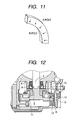
- Fig. 11 is magnet of the present invention;
- Fig. 12 is the embodiment of final gear for mounting the present invention.
- the electronic control throttle valve unit mainly comprises throttle body (hereinafter may also be called simply as the body) 1, throttle valve 4, motor (throttle valve drive; electric actuator) 22 for driving the throttle valve 4, reduction gear mechanism 100, and cover 16 for protecting the throttle valve shaft 3, motor 22 and reduction mechanism 100.
- the throttle valve 4 is mounted on the throttle valve shaft 3 with screws 5, and the throttle valve shaft 3 is supported by the bearing 6 attached to the body 1.
- One end of the throttle valve shaft 3 projects out of the side wall of the body 1.
- spring 10, lever 9, spring 11 and the final gear (driven gear) 12 of the reduction gear mechanism 100 are mounted, about which description is made later.
- the throttle valve shaft 3 and the final gear (driven gear) 12 of the reduction gear mechanism 100 are so connected that their angle to each other does not shift. Accordingly, the throttle valve 4 and final gear 12 have the same displacement angle and they are synchronized with each other in terms of angle.
- throttle valve mechanism Components related to the throttle valve such as throttle valve shaft 3, reduction gear mechanism 100 and motor 22 (hereinafter called the throttle valve mechanism) are contained in a storage section provided on the side wall of the body 1 and the storage section is covered by a synthetic resin cover 16.
- the cover 16 is molded out of resin mixed with magnetic force isolation material powder so that the disturbance of the electromagnetic wave falling over the EC throttle does not enter inside the cover 16.
- the cover is molded over a magnetic force isolation plate out of resin material mixed with a specified amount of at lease one of the magnetic force isolation materials, Permalloy powder, Sendust cast powder and Fe-B amorphous powder.
- the magnetic force isolation plate produced as above shows higher productivity than a magnetic force isolation plate that is resin molded over a metallic plate having magnetic force isolation characteristic. In concrete terms, neither positioning process nor machining process of the isolation plate itself is needed.
- the motor 22 is driven according to an acceleration signal, relating to the depth of pushing down the accelerator pedal, traction control signal, constant speed drive signal, and idling speed control signal, and the power of the motor 22 is transmitted to the throttle valve shaft 3 via the reduction gear mechanism 100 (motor pinion 21, intermediate gear 20 and final gear 12).
- the pinion 21 is attached to the motor shaft 27 and the intermediate gear 20 engages freely with the conductive shaft 19 attached to the throttle body 1.
- the major gear 20a of the intermediate gear 20 engages with the pinion 21 and the minor gear 20b engages with the final gear 12.
- the final gear 12 is a fan-shaped resin gear.
- a metallic plate 12a is attached to the end of the throttle valve shaft 3 with bolt 120.
- the metallic plate 12a has some holes in it so that resin flows over both sides of the metallic plate in resin molding.
- the fan-shaped final gear 12 is resin molded.
- the magnet 15 (32) is mounted by resin molding at a position apart circumferentially from the final gear 12 by 180 degrees.
- the relationship between the final gear 12 and lever 9 is as follows.
- the spring 10 is a return spring of the throttle valve; one end is hooked on a spring hook (not shown) attached to the body 1 and the other end is hooked on the lever 9.
- the spring 10 gives a return force to the throttle valve shaft via the lever 9 and final gear 12. Furthermore, it constitutes a well-known, so-called default opening setting mechanism. Default opening setting mechanism is to maintain the initial opening of the throttle valve 4 at an opening greater than the fully closed position in case the engine key is turned off or the motor 22, an electric actuator is not energized, for example in case of a failure in an electric power line.
- the throttle valve opening is determined by the balance between the torque of the motor 22 and valve closing force of the spring (return spring) 10.
- the rotation angle sensing device comprises the arcuate magnet 15 mounted on the final gear 12, stators 13 and 14 constituting at least two magnetic circuitry members installed along the rotation axis of the throttle valve 3 on the inside of the peripheral wall of the cover 16 as if the magnet 15 is positioned between them, and at lease one Hall element 25 so mounted on the cover 16 as to be positioned between the ends of the two magnetic circuitry members, and the arcuate magnet 15 is moved into and out of an arcuate gap (arcuate groove) between the stators 13 and 14 constituting two magnetic circuitry members, as the final gear 12 rotates.
- the magnetic circuitry members are fixed inside the surface of the cover 16 perpendicular to the throttle valve shaft 3 so that the magnet 15 is positioned between the inside and outside of the circumference concentric with the throttle valve shaft 3 (see Fig. 6), and a magnet 32, which is magnetized radially so that the magnetic flux density is different between the inside and outside arc of the magnet 32 as shown in Fig. 11, is employed.
- a magnet 32 which is magnetized radially so that the magnetic flux density is different between the inside and outside arc of the magnet 32 as shown in Fig. 11, is employed.
- linear rotation angle sensor output can be obtained in accordance with the rotation of the throttle valve 4.
- the magnetic circuitry members With a construction where the magnetic circuitry members are fixed on the cover 16 covering the gear as above, the magnetic circuitry members can be installed easily. In particular, since magnetic circuitry member can be resin molded into one piece with the cover to be molded, much better workability can be achieved.
- the device can remain functional only in case the Hall element 25 has failed.
- the Hall element and magnetic circuitry are mounted in two separate lines, the device can remain functional in case either the Hall element 24 or 25 has failed and also in case a magnetic circuitry itself has failed.
- the magnet 15 (32) projecting out of the magnetic circuitry disturbs the magnetic field around it, and hence gives adverse impact on the magnetic circuitry itself.
- the rotation angle sensing device equipped with two lines of magnetic circuitries like the one according to this embodiment because the magnet 15 (32) projecting out of one magnetic circuitry is moved into the other magnetic circuitry, it does not disturb the magnetic field around it, and hence the rotation angle sensing accuracy improves.
- the magnetic circuitry members (stators) 13 (30), 14 (31), 17 (33) and 18 (34) and magnet 15 are arcuate and all located on the same circumferential plane, and the circumferential angle is greater than the rotation angle of the valve.
- the direction of the magnetic force line must be turned so that the magnetic force line running in the arcuate direction through the magnetic circuitry members (stators) 13 (30), 14 (31), 17 (33) and 18 (34) passes through the Hall element 24 and 25.
- the magnetic circuitry members (stators) 13 (30), 14 (31), 17 (33) and 18 (34) themselves are slightly extended towards the Hall element 24 and 25.
- the circumferential angle of the magnet 15 (32) is made larger so that, while the magnet 15 (32) is moved into the utmost of one circuitry, some magnetic flux still runs in the other magnetic circuitry. This measure is to prevent reduction of the magnet flux quantity passing through the Hall element 24 or 25, which is caused as the magnetic flux runs from the magnetic circuitry of which the magnet 15 (32) is moved into the utmost to the other magnetic circuitry.
- the surface of the magnet 15 (32) facing the magnetic circuitry member (stator) 13 (30), 14 (31), 17 (33) and 18 (34) is made each polar surface.
- the N-pole and S-pole can be on either side.
- the magnet 15 (32) is fixed by including it partly of wholly into one piece with the gear to be molded. If the magnet 15 (32) is completely included in the resin, it can be expected that the magnet is protected from any external force or effect.
- the magnet 15 (32) for the EC throttle is installed on the final gear 12 at a position apart from the motor 22. It is installed, for example, at a position opposite to the tooth block of the final gear 12 by an angle of about 180 degrees.
- the magnet can be set apart from the motor 22 that drives the throttle valve shaft and so the effect of the magnetic field variation caused by the motor 22 upon the magnetic circuitry of the sensor can be reduced.
- the Hall element 24 and 25 senses the change in the magnetic field and generates a Hall voltage.
- the Hall element 24 and 25 and magnetic circuitry members (stators) 13 (30), 14 (31), 17 (33) and 18 (34) are fixed on the cover 16 and partly or wholly included into one piece with the cover 16 to be molded as shown in Fig. 2. With this construction, it can be expected that the magnetic circuitry members (stators) 13 (30), 14 (31), 17 (33) and 18 (34) are prevented from falling down and the Hall element is protected.
- the magnetism sensing device 24 and 25 can be connected to a conductor that is mechanically fixed by being included into one piece with the resin molded cover 16 so as to send a signal to an external device via the electric terminal (connected to the conductor) of the connector 16b which is also included into one piece with the resin molded cover 16.
- the engine control unit of a motor vehicle is equipped with a coupler and signal line to be connected to the connector 16b, and the output signal from the Hall element 24 and 25 is inputted into the engine control unit.
- the control unit corrects the control parameters of the internal combustion engine, including the fuel injection pulse width and throttle valve opening, and controls the change-speed point of the auto transmission based on the electrical signal corresponding to the change in the magnetic field or on the electrical signal and at least one other electrical signal, such as a signal indicating the vehicle speed, where the change in the magnetic field is the change in the magnetic physical quantity that varies depending upon how much the magnet 15 (32) and the magnetic circuitry members (stators) 13 (30), 14 (31), 17 (33) and 18 (34) overlap or how much the magnet 15 (32) is moved into the arcuate gap (groove) formed by the magnetic circuitry members (stators) 13 (30), 14 (31), 17 (33) and 18 (34).
- the change in the magnetic field is the change in the magnetic physical quantity that varies depending upon how much the magnet 15 (32) and the magnetic circuitry members (stators) 13 (30), 14 (31), 17 (33) and 18 (34) overlap or how much the magnet 15 (32) is moved into the arcuate gap (groove) formed by the
- control parameters of the engine is adjusted in accordance with the change in the electrical signal, corresponding to the opening of the throttle valve shaft, that is outputted from the Hall element 24 and 25 in accordance with the magnetic signal change resulting from the positional relationship between the arcuate magnet 15 mounted on the end of the throttle valve shaft and the arcuate magnet circuitry members.
- the opening signal of the throttle valve 4 which is outputted from the Hall element 24 and 25 as the change in the electrical signal, has little factor of aging. Thus, exact adjustment of the control parameters of the internal combustion engine can be maintained for a long period of time.
- the final gear 12 is made of synthetic resin, the final gear 12 does not give any adverse impact upon the magnetic field generated by the magnet 15 (32).
- a metallic plate is used as the center portion that engages with the throttle valve shaft 3.
- the whole gear is molded out of resin and the engagement between the throttle valve shaft 3 and final gear 12 is positioned inside the spring 10 that is made of magnetic material as shown in Fig. 12, disturbance of the magnetic field is absorbed by the spring 10 and so magnetic adverse impact can further be eliminated.
- the induction characteristic of the Hall element 24 and 25 can always be constant irrespective of the rotation angle of the throttle shaft.
- the magnetism sensing device can be made compact since it is made into a fan shape and installed outside the intermediate gear.
- the rotation bearing shaft of the intermediate gear 20 located between the motor 22 and magnetic type non-contact sensor is made of magnetic material, electromagnetic effect resulting from the change in the drive current of the motor 22 can be expected to be shielded by the rotation bearing shaft 19, and so the Hall element 24 and 25 hardly receives the electromagnetic effect of the motor 22 and the sensing accuracy of the Hall element 24 and 25 can hardly be disturbed.
- throttle body is an essential component that determines the vehicle speed and output torque.
- the throttle valve is controlled by the feedback sensor according to electrical signals needs to have high accuracy and reliability.
- a magnetic circuitry of the rotation angle sensing device having two output lines comprises at least one magnet, at least two magnetic circuitries and at lease one Hall element, but how it is constructed is not shown and so its effect is uncertain.
- a rotation angle sensing device having two output lines uses two Hall elements to be mounted in a single magnetic circuitry. Because the device has only one magnetic circuitry, it cannot remain functional in case of a failure of the magnetic circuitry itself such as falling down or corrosion of the magnetic circuitry members.
- a sensing device having two lines can be constructed easily and, even in case of a failure of one sensor, the other sensor can back up the function of the device.
- the magnet projecting out of the magnetic circuitry disturbs the magnetic field space around it and gives an adverse impact upon the magnetic circuitry itself, resulting in the deterioration of the rotation angle sensing accuracy.
- the magnet can be contained inside the gap of the stator regardless of wherever it is positioned, and hence the magnet does not disturb the magnetic field space around it and gives no adverse impact upon the magnetic circuitry itself.
- an expensive magnet made of, for example, neodymium that exhibits greater magnetic force from the beginning is needed.
- the device manufactured in this method does not cause any change in the characteristic and deterioration of the magnetic force. Accordingly, a less-expensive magnet can be employed.
- the distance between the magnet and magnetic circuitry members is kept constant so that the opposed area between the magnet and magnetic circuitry members is changed proportionally corresponding to the change of the angle of the object to be sensed.
- the output voltage of the Hall element can be changed proportionally corresponding to the change of the angle of the object to be sensed.
- the present invention it becomes possible to realize a sensor with an output characteristic that the output signal of the sensing element can be changed proportionally corresponding to the change of the angle of the object to be sensed and that the range of angle where a linear sensor output can be obtained is wide.
Landscapes
- Engineering & Computer Science (AREA)
- Chemical & Material Sciences (AREA)
- Combustion & Propulsion (AREA)
- Mechanical Engineering (AREA)
- General Engineering & Computer Science (AREA)
- Physics & Mathematics (AREA)
- General Physics & Mathematics (AREA)
- Measurement Of Length, Angles, Or The Like Using Electric Or Magnetic Means (AREA)
- Control Of Throttle Valves Provided In The Intake System Or In The Exhaust System (AREA)
Applications Claiming Priority (2)
| Application Number | Priority Date | Filing Date | Title |
|---|---|---|---|
| JP2003128545 | 2003-05-07 | ||
| JP2003128545A JP2004332603A (ja) | 2003-05-07 | 2003-05-07 | 回転角検出装置,電子制御スロットル弁装置,スロットル弁軸の回転角度を検出するセンサの製造方法及び内燃機関 |
Publications (2)
| Publication Number | Publication Date |
|---|---|
| EP1475525A2 true EP1475525A2 (de) | 2004-11-10 |
| EP1475525A3 EP1475525A3 (de) | 2005-10-26 |
Family
ID=32985632
Family Applications (1)
| Application Number | Title | Priority Date | Filing Date |
|---|---|---|---|
| EP04010818A Withdrawn EP1475525A3 (de) | 2003-05-07 | 2004-05-06 | Winkelsensor für eine elektronische Drosselklappe und Verfahren zur Herstellung dieses Winkelsensors |
Country Status (3)
| Country | Link |
|---|---|
| US (1) | US20040251893A1 (de) |
| EP (1) | EP1475525A3 (de) |
| JP (1) | JP2004332603A (de) |
Cited By (5)
| Publication number | Priority date | Publication date | Assignee | Title |
|---|---|---|---|---|
| FR2882817A1 (fr) * | 2005-10-03 | 2006-09-08 | Siemens Vdo Automotive Sas | Procede d'optimisation des performances d'un capteur de position electromagnetique, et capteur de position realise. |
| WO2009019055A2 (de) * | 2007-08-07 | 2009-02-12 | Robert Bosch Gmbh | Stellorgan |
| US20110050012A1 (en) * | 2007-08-16 | 2011-03-03 | Pierburg Gmbh | Electrical internal combustion engine actuating arrangement |
| WO2011139469A1 (en) * | 2010-05-05 | 2011-11-10 | Continental Automotive Systems, Inc. | Rotary arc position sensor with linear output |
| WO2013022390A1 (en) * | 2011-08-08 | 2013-02-14 | Husqvarna Ab | A magnet holder for use in a throttle position sensor, a magnet holder for use in an angular position sensor, and methods for manufacturing them |
Families Citing this family (5)
| Publication number | Priority date | Publication date | Assignee | Title |
|---|---|---|---|---|
| JP4433886B2 (ja) * | 2004-06-02 | 2010-03-17 | 株式会社デンソー | 回転角度検出装置 |
| JP2009145076A (ja) * | 2007-12-11 | 2009-07-02 | Hitachi Cable Ltd | 回転角度検出装置 |
| JP2014137005A (ja) * | 2013-01-16 | 2014-07-28 | Denso Corp | バルブ装置 |
| US10036653B2 (en) * | 2014-10-06 | 2018-07-31 | Te Connectivity Corporation | Relative angle sensor |
| CN113931741A (zh) * | 2021-09-22 | 2022-01-14 | 深圳拓邦股份有限公司 | 一种发动机活动门开度检测系统、发动机及车辆 |
Citations (4)
| Publication number | Priority date | Publication date | Assignee | Title |
|---|---|---|---|---|
| US6232771B1 (en) * | 1996-08-24 | 2001-05-15 | Robert Bosch Gmbh | Device for contactless measurement of angle of rotation of linear motion between rotor and stator composed of a plurality of parts |
| US20010002599A1 (en) * | 1999-01-29 | 2001-06-07 | Ab Elektronik Gmbh | Hall effect rotation sensor for a throttle valve unit |
| US20010030534A1 (en) * | 2000-02-15 | 2001-10-18 | Peter Apel | Rotation angle sensor |
| US6518749B1 (en) * | 1997-06-04 | 2003-02-11 | Mmt (S. A.) | Magnetic sensor for delivery of an electrical signal proportional to position |
Family Cites Families (1)
| Publication number | Priority date | Publication date | Assignee | Title |
|---|---|---|---|---|
| JP3757118B2 (ja) * | 2001-01-10 | 2006-03-22 | 株式会社日立製作所 | 非接触式回転位置センサ及び非接触式回転位置センサを有する絞弁組立体 |
-
2003
- 2003-05-07 JP JP2003128545A patent/JP2004332603A/ja active Pending
-
2004
- 2004-05-06 US US10/839,698 patent/US20040251893A1/en not_active Abandoned
- 2004-05-06 EP EP04010818A patent/EP1475525A3/de not_active Withdrawn
Patent Citations (4)
| Publication number | Priority date | Publication date | Assignee | Title |
|---|---|---|---|---|
| US6232771B1 (en) * | 1996-08-24 | 2001-05-15 | Robert Bosch Gmbh | Device for contactless measurement of angle of rotation of linear motion between rotor and stator composed of a plurality of parts |
| US6518749B1 (en) * | 1997-06-04 | 2003-02-11 | Mmt (S. A.) | Magnetic sensor for delivery of an electrical signal proportional to position |
| US20010002599A1 (en) * | 1999-01-29 | 2001-06-07 | Ab Elektronik Gmbh | Hall effect rotation sensor for a throttle valve unit |
| US20010030534A1 (en) * | 2000-02-15 | 2001-10-18 | Peter Apel | Rotation angle sensor |
Cited By (12)
| Publication number | Priority date | Publication date | Assignee | Title |
|---|---|---|---|---|
| FR2882817A1 (fr) * | 2005-10-03 | 2006-09-08 | Siemens Vdo Automotive Sas | Procede d'optimisation des performances d'un capteur de position electromagnetique, et capteur de position realise. |
| WO2009019055A2 (de) * | 2007-08-07 | 2009-02-12 | Robert Bosch Gmbh | Stellorgan |
| WO2009019055A3 (de) * | 2007-08-07 | 2009-04-16 | Bosch Gmbh Robert | Stellorgan |
| US8717011B2 (en) | 2007-08-07 | 2014-05-06 | Robert Bosch Gmbh | Actuator |
| US20110050012A1 (en) * | 2007-08-16 | 2011-03-03 | Pierburg Gmbh | Electrical internal combustion engine actuating arrangement |
| US8314524B2 (en) * | 2007-08-16 | 2012-11-20 | Pierburg Gmbh | Electrical internal combustion engine actuating arrangement |
| WO2011139469A1 (en) * | 2010-05-05 | 2011-11-10 | Continental Automotive Systems, Inc. | Rotary arc position sensor with linear output |
| CN102869954A (zh) * | 2010-05-05 | 2013-01-09 | 大陆汽车系统公司 | 具有线性输出的旋转弧位置传感器 |
| CN102869954B (zh) * | 2010-05-05 | 2016-01-06 | 大陆汽车系统公司 | 具有线性输出的旋转弧位置传感器 |
| US9841296B2 (en) | 2010-05-05 | 2017-12-12 | Continental Automotive Systems, Inc. | Rotary arc position sensor with linear output |
| WO2013022390A1 (en) * | 2011-08-08 | 2013-02-14 | Husqvarna Ab | A magnet holder for use in a throttle position sensor, a magnet holder for use in an angular position sensor, and methods for manufacturing them |
| US9605599B2 (en) | 2011-08-08 | 2017-03-28 | Husqvarna Ab | Magnet holder for use in a throttle position sensor, a magnet holder for use in an angular position sensor, and methods for manufacturing them |
Also Published As
| Publication number | Publication date |
|---|---|
| US20040251893A1 (en) | 2004-12-16 |
| EP1475525A3 (de) | 2005-10-26 |
| JP2004332603A (ja) | 2004-11-25 |
Similar Documents
| Publication | Publication Date | Title |
|---|---|---|
| JP4115388B2 (ja) | バタフライバルブ接続ピース | |
| EP1533593B1 (de) | Magnetischer Rotationssensor | |
| US7367315B2 (en) | Throttle valve control apparatus of internal combustion engine and automobile using the same | |
| US6923157B2 (en) | Throttle device for internal combustion engine | |
| JP4494368B2 (ja) | 電子制御スロットル装置 | |
| JP3893907B2 (ja) | 内燃機関用吸気制御装置 | |
| JP4098149B2 (ja) | スロットル制御装置 | |
| US5742106A (en) | Thermo-sensitive actuator and idle speed controller employing the same | |
| EP1929148B1 (de) | Positionssensor mit variabler reluktanz | |
| EP1475525A2 (de) | Winkelsensor für eine elektronische Drosselklappe und Verfahren zur Herstellung dieses Winkelsensors | |
| EP1647808A1 (de) | Regler und im Grätschsitz zu benutzendes Fahrzeug | |
| JP2005054654A (ja) | エンジン用吸気制御装置 | |
| JP2005048671A (ja) | エンジン用吸気制御装置 | |
| JP2005345250A (ja) | 回転角度検出装置 | |
| US5996554A (en) | Throttle valve control device | |
| EP1096235A2 (de) | Magnetischer Rotationssensor | |
| JP4259315B2 (ja) | 電子制御式スロットル制御装置 | |
| US20070108968A1 (en) | Rotation angle detection device | |
| JP5757285B2 (ja) | 位置検出装置 | |
| JP3539299B2 (ja) | 回転角検出装置 | |
| JP2014126553A (ja) | 位置検出装置 | |
| JP5720961B2 (ja) | 位置検出装置 | |
| US7365503B2 (en) | Hall Effect sensor temperature compensator | |
| JP2004245703A (ja) | 回転角検出装置 | |
| JP4883026B2 (ja) | 回転角度検出装置 |
Legal Events
| Date | Code | Title | Description |
|---|---|---|---|
| PUAI | Public reference made under article 153(3) epc to a published international application that has entered the european phase |
Free format text: ORIGINAL CODE: 0009012 |
|
| AK | Designated contracting states |
Kind code of ref document: A2 Designated state(s): AT BE BG CH CY CZ DE DK EE ES FI FR GB GR HU IE IT LI LU MC NL PL PT RO SE SI SK TR |
|
| AX | Request for extension of the european patent |
Extension state: AL HR LT LV MK |
|
| RIC1 | Information provided on ipc code assigned before grant |
Ipc: 7G 01B 7/14 B Ipc: 7G 01B 7/30 B Ipc: 7G 01D 5/14 B Ipc: 7F 02D 35/00 B Ipc: 7F 02D 11/10 B Ipc: 7F 02D 9/00 B Ipc: 7F 02D 9/10 A |
|
| PUAL | Search report despatched |
Free format text: ORIGINAL CODE: 0009013 |
|
| AK | Designated contracting states |
Kind code of ref document: A3 Designated state(s): AT BE BG CH CY CZ DE DK EE ES FI FR GB GR HU IE IT LI LU MC NL PL PT RO SE SI SK TR |
|
| AX | Request for extension of the european patent |
Extension state: AL HR LT LV MK |
|
| 17P | Request for examination filed |
Effective date: 20060220 |
|
| AKX | Designation fees paid |
Designated state(s): DE FR IT |
|
| 17Q | First examination report despatched |
Effective date: 20060711 |
|
| STAA | Information on the status of an ep patent application or granted ep patent |
Free format text: STATUS: THE APPLICATION IS DEEMED TO BE WITHDRAWN |
|
| 18D | Application deemed to be withdrawn |
Effective date: 20070123 |