EP1474591B1 - Druckluftmotor - Google Patents
Druckluftmotor Download PDFInfo
- Publication number
- EP1474591B1 EP1474591B1 EP03702831A EP03702831A EP1474591B1 EP 1474591 B1 EP1474591 B1 EP 1474591B1 EP 03702831 A EP03702831 A EP 03702831A EP 03702831 A EP03702831 A EP 03702831A EP 1474591 B1 EP1474591 B1 EP 1474591B1
- Authority
- EP
- European Patent Office
- Prior art keywords
- compressed
- air motor
- rotor
- vanes
- motor according
- Prior art date
- Legal status (The legal status is an assumption and is not a legal conclusion. Google has not performed a legal analysis and makes no representation as to the accuracy of the status listed.)
- Expired - Lifetime
Links
Images

Classifications
-
- F—MECHANICAL ENGINEERING; LIGHTING; HEATING; WEAPONS; BLASTING
- F04—POSITIVE - DISPLACEMENT MACHINES FOR LIQUIDS; PUMPS FOR LIQUIDS OR ELASTIC FLUIDS
- F04C—ROTARY-PISTON, OR OSCILLATING-PISTON, POSITIVE-DISPLACEMENT MACHINES FOR LIQUIDS; ROTARY-PISTON, OR OSCILLATING-PISTON, POSITIVE-DISPLACEMENT PUMPS
- F04C18/00—Rotary-piston pumps specially adapted for elastic fluids
- F04C18/30—Rotary-piston pumps specially adapted for elastic fluids having the characteristics covered by two or more of groups F04C18/02, F04C18/08, F04C18/22, F04C18/24, F04C18/48, or having the characteristics covered by one of these groups together with some other type of movement between co-operating members
- F04C18/34—Rotary-piston pumps specially adapted for elastic fluids having the characteristics covered by two or more of groups F04C18/02, F04C18/08, F04C18/22, F04C18/24, F04C18/48, or having the characteristics covered by one of these groups together with some other type of movement between co-operating members having the movement defined in group F04C18/08 or F04C18/22 and relative reciprocation between the co-operating members
- F04C18/344—Rotary-piston pumps specially adapted for elastic fluids having the characteristics covered by two or more of groups F04C18/02, F04C18/08, F04C18/22, F04C18/24, F04C18/48, or having the characteristics covered by one of these groups together with some other type of movement between co-operating members having the movement defined in group F04C18/08 or F04C18/22 and relative reciprocation between the co-operating members with vanes reciprocating with respect to the inner member
- F04C18/348—Rotary-piston pumps specially adapted for elastic fluids having the characteristics covered by two or more of groups F04C18/02, F04C18/08, F04C18/22, F04C18/24, F04C18/48, or having the characteristics covered by one of these groups together with some other type of movement between co-operating members having the movement defined in group F04C18/08 or F04C18/22 and relative reciprocation between the co-operating members with vanes reciprocating with respect to the inner member the vanes positively engaging, with circumferential play, an outer rotatable member
-
- F—MECHANICAL ENGINEERING; LIGHTING; HEATING; WEAPONS; BLASTING
- F01—MACHINES OR ENGINES IN GENERAL; ENGINE PLANTS IN GENERAL; STEAM ENGINES
- F01C—ROTARY-PISTON OR OSCILLATING-PISTON MACHINES OR ENGINES
- F01C1/00—Rotary-piston machines or engines
- F01C1/30—Rotary-piston machines or engines having the characteristics covered by two or more groups F01C1/02, F01C1/08, F01C1/22, F01C1/24 or having the characteristics covered by one of these groups together with some other type of movement between co-operating members
- F01C1/34—Rotary-piston machines or engines having the characteristics covered by two or more groups F01C1/02, F01C1/08, F01C1/22, F01C1/24 or having the characteristics covered by one of these groups together with some other type of movement between co-operating members having the movement defined in group F01C1/08 or F01C1/22 and relative reciprocation between the co-operating members
- F01C1/344—Rotary-piston machines or engines having the characteristics covered by two or more groups F01C1/02, F01C1/08, F01C1/22, F01C1/24 or having the characteristics covered by one of these groups together with some other type of movement between co-operating members having the movement defined in group F01C1/08 or F01C1/22 and relative reciprocation between the co-operating members with vanes reciprocating with respect to the inner member
- F01C1/348—Rotary-piston machines or engines having the characteristics covered by two or more groups F01C1/02, F01C1/08, F01C1/22, F01C1/24 or having the characteristics covered by one of these groups together with some other type of movement between co-operating members having the movement defined in group F01C1/08 or F01C1/22 and relative reciprocation between the co-operating members with vanes reciprocating with respect to the inner member the vanes positively engaging, with circumferential play, an outer rotatable member
-
- F—MECHANICAL ENGINEERING; LIGHTING; HEATING; WEAPONS; BLASTING
- F04—POSITIVE - DISPLACEMENT MACHINES FOR LIQUIDS; PUMPS FOR LIQUIDS OR ELASTIC FLUIDS
- F04C—ROTARY-PISTON, OR OSCILLATING-PISTON, POSITIVE-DISPLACEMENT MACHINES FOR LIQUIDS; ROTARY-PISTON, OR OSCILLATING-PISTON, POSITIVE-DISPLACEMENT PUMPS
- F04C2250/00—Geometry
- F04C2250/10—Geometry of the inlet or outlet
-
- F—MECHANICAL ENGINEERING; LIGHTING; HEATING; WEAPONS; BLASTING
- F05—INDEXING SCHEMES RELATING TO ENGINES OR PUMPS IN VARIOUS SUBCLASSES OF CLASSES F01-F04
- F05C—INDEXING SCHEME RELATING TO MATERIALS, MATERIAL PROPERTIES OR MATERIAL CHARACTERISTICS FOR MACHINES, ENGINES OR PUMPS OTHER THAN NON-POSITIVE-DISPLACEMENT MACHINES OR ENGINES
- F05C2223/00—Cellulosic materials, e.g. wood
-
- F—MECHANICAL ENGINEERING; LIGHTING; HEATING; WEAPONS; BLASTING
- F05—INDEXING SCHEMES RELATING TO ENGINES OR PUMPS IN VARIOUS SUBCLASSES OF CLASSES F01-F04
- F05C—INDEXING SCHEME RELATING TO MATERIALS, MATERIAL PROPERTIES OR MATERIAL CHARACTERISTICS FOR MACHINES, ENGINES OR PUMPS OTHER THAN NON-POSITIVE-DISPLACEMENT MACHINES OR ENGINES
- F05C2253/00—Other material characteristics; Treatment of material
- F05C2253/04—Composite, e.g. fibre-reinforced
Definitions
- the invention relates to an oil-free operated air motor with a guide bore having housing and a rotor rotatably mounted therein, wherein the rotor is provided with outwardly extending slots in which plate-shaped fins are mounted radially displaceable by the centrifugal force and in the region of the fins between the outside the rotor and the guide bore of the housing is arranged a substantially cylindrical, freely rotatable flight sleeve surrounding the outside of the slats and the flight sleeve has on its jacket a plurality of passages for the compressed air and wherein the flight sleeve and / or the slats are made of plastic.
- the prior art knows various types of vane motors (Vane engines), which are to be operated with compressed air.
- the European patent EP-B1-394651 describes a structure with a rotor and centrifugal sliding slats, wherein the rotor is disposed in a flight sleeve, which is housed within a bore of a housing.
- This flight sleeve has the task of preventing the slats on the inner wall of the housing shy. During operation, the rotor and the flight sleeve thus rotate.
- the bore of the housing is not cylindrical in this known structure, but on one side by a pocket non-cylindrically deformed. This is because it was obviously believed that a compressed air supply is required in the space between the flight sleeve and the outer cylinder wall. As a further reason, the one-sided extra-cylindrical deformation has presumably become necessary because, due to the pressure load of the axially flowing compressed air into the space between the rotor and the flight sleeve, a tendency to side shift of the flight sleeve resulted could be compensated by the additional radial clearance in the recess.
- the pneumatic motors with flight sleeve specified in the prior art are designed to reduce the friction which occurs between the disks and the outer housing in other pneumatic motors, thereby enabling oil-free operation.
- the US4120623 discloses a pneumatic motor according to the preamble of claim 1.
- the invention is therefore an object of the invention to provide an oil-free operable air motor with improved efficiency, the production should not be particularly difficult.
- the air connections for air inlet and Heilaustass need not be specially formed in the inventive system, they are preferably deburred, or sandblasted to improve the flow efficiency yet.
- the rotor may be provided with non-radial blades, but preferably the blades are arranged in radial slots and not force controlled.
- a material for the lamellae and / or for the flight sleeve plastic especially phenolic resin-cotton fabric is used.
- the passage openings in the flight sleeve are arranged distributed irregularly on the circumference and / or over the length of the flight sleeve. They can be distributed differently according to the needs and depending on the length of the flight sleeve depending, or designed differently.
- the passage openings are preferably statistically or randomly distributed with regard to the noise-optimized behavior of the flight sleeve, that is to say that there are as far as possible no regular distances between the holes in the circumferential direction of the flight sleeve. This prevents that at the high speeds in the air medium dominant tones can be generated.
- the passage openings n can also be arranged distributed so that the passage openings deliberately generate complementary tones, so that a "white noise" (i.e., a noise inaudible to the observer) arises
- the passage openings are advantageously formed as substantially radially extending bores. Holes are very simple and economical to produce.
- passage openings are formed as slots. By varying the length and width of the slots, the desired passage cross-section can be optimally determined.
- the slots advantageously extend substantially in the longitudinal direction of the flight sleeve.
- the slots are substantially helical. Due to the helical shape, the noise level can be reduced and a smoother running of the rotor can be achieved.
- a noise-enhancing effect of the type described above can also be achieved in that the lamellae are not arranged distributed symmetrically exactly on the circumference of the rotor.
- the flight sleeve and / or the lamellae are preferably made of phenolic resin-cotton fabric. On the one hand, this results in a low weight and, associated therewith, a small flywheel, so that such air motors are very dynamic, i. can be operated with a strong speed change.
- the longitudinal slots for the slats are arranged approximately parallel offset from the radial planes. This results in a larger surface acted upon by the compressed air than in radially arranged fins.
- fins Preferably, four fins are provided, but the invention is not limited thereto and more or fewer fins may be provided depending on the diameter and the choice of material.
- the out Fig.1 and 2 apparent air motor consists essentially of a multi-part, generally designated 1 housing.
- a rotor 2 is rotatably mounted by means of bearings 3.4
- the central region of the housing 1 has a substantially cylindrical guide bore 5.
- a tool holder 6 At the front end of the rotor 2 is a tool holder 6.
- the rotor 2 has four substantially radially extending longitudinal slots 7. In the longitudinal slots 7 slats 8 are guided radially displaceable.
- a flight sleeve 9 surrounds the outer end side of the fins 8 and is in the guide bore 5 of the housing 1 freely rotatably mounted.
- the flight sleeve 9 rotates with the rotor 2 in the housing 1, wherein the rotational drive between the rotor 2 and the flight sleeve 9 takes place only by friction between the blades 8 and the flight sleeve 9.
- the flight sleeve 9 prevents the contact of the fins 8 with the guide bore 5 and thus also associated Abnönungserscheinept the fins 8 and the guide bore 5.
- the supply of compressed air via a feed channel 12, which opens at the rear end side of the rotor 2 in the guide bore 5 ,
- the air outlet 13 is located on the supply channel 12 approximately radially opposite side.
- the flight sleeve 9 is provided with average openings 10,11. These average openings 10,11 are used to pass the compressed air from the formed between the fins 8, the outside of the rotor 2 and the inside of the flight sleeve 9 chambers 14. By the passage of a portion of the compressed air is also on the outside of the flight sleeve 9 an air cushion built , This prevents that the flying sleeve 9 is pressed by the internal pressure on one side against the bore of the housing 1 and thereby it comes to a large wear between the flight sleeve 9 and the housing 1.
- the average openings 10, 11 may be formed, for example, as bores or as slots.
- the passage openings 10,11 are preferably axially and / or radially arranged offset from each other. However, this displacement of the passage openings can be positively influenced by the high speeds (up to approximately 80,000 rpm) that are produced by such devices.
- the lamellae 8 and / or the flight sleeve 9 are made of a plastic, in particular phenolic resin-cotton fabric. On the one hand, this results in a low weight and, associated therewith, a small flywheel mass, so that such compressed air motors can be operated very dynamically, ie with a high speed change.
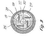
- the out Fig. 3 apparent cross section through a further embodiment of an inventive compressed air motor shows a housing 21 and a rotor 22nd
- the housing 21 has a guide bore 25.
- the rotor 22 is provided with longitudinal slots 27, which, however, in contrast to the in Fig. 2 illustrated embodiment do not extend radially, but are arranged in a plane offset parallel to the radial plane.
- In the longitudinal slots 27 also slats 28 are slidably mounted.
- a flight sleeve 29 surrounds the outside of the lamellae 28 and is mounted in the guide bore 25 of the housing 1.
- the flight sleeve 29 is provided with at least one average opening 30. Through the average opening 30 compressed air can enter the annular gap between the housing 21 and the flight sleeve 29.
- the average opening 30 can be arranged axially and / or radially at different locations of the flight sleeve 29. It is also possible to provide a plurality of openings on the circumference of the flight sleeve, wherein the average openings, for example, can be formed as holes or as slots.
- Both the flight sleeve 29 and the fins 28 are preferably made of a plastic, for example. Phenoiharz-Baumwottfeinstgewebe.
Landscapes
- Engineering & Computer Science (AREA)
- Mechanical Engineering (AREA)
- General Engineering & Computer Science (AREA)
- Rotary Pumps (AREA)
- Motor Or Generator Frames (AREA)
- Structures Of Non-Positive Displacement Pumps (AREA)
- Exhaust Gas After Treatment (AREA)
- Engine Equipment That Uses Special Cycles (AREA)
Description
- Die Erfindung betrifft einen ölfrei betreibbaren Druckluftmotor mit einem eine Führungsbohrung aufweisenden Gehäuse und einem darin drehbar gelagerten Rotor, wobei der Rotor mit nach aussen verlaufenden Schlitzen versehen ist, in denen plattenförmige Lamellen durch die Fliehkraft radial verschiebbar gelagert sind und im Bereich der Lamellen zwischen der Aussenseite des Rotors und der Führungsbohrung des Gehäuses eine die Aussenseite der Lamellen umhüllende, im wesentlichen zylindrische, frei rotierbare Flughülse angeordnet ist und die Flughülse an ihrem Mantel mehrere Durchtrittsöffnungen für die Druckluft aufweist und wobei die Flughülse und/oder die Lamellen aus Kunststoff bestehen.
- Der Stand der Technik kennt verschiedene Arten von Lamellenmotoren (Vane - Motoren), die mit Druckluft zu betreiben sind. Das europäische Patent
EP-B1-394651 - Diese Flughülse hat die Aufgabe, zu verhindern, dass die Lamellen an der Innenwand des Gehäuses scheuem. Im Betrieb drehen sich somit der Rotor und die Flughülse.
- Die Bohrung des Gehäuses ist bei diesem bekannten Aufbau nicht Zylinderförmig, sondern an einer Seite durch eine Tasche nicht-zylindrisch verformt. Dies deshalb, weil man offensichtlich der Ansicht war, dass eine Druckluftzuführung in den Raum zwischen der Flughülse und der äusseren Zylinderwand erforderlich ist. Als weiterer Grund ist die einseitige ausserzylindrische Verformung vermutlich erforderlich geworden, weil sich durch die Druckbelastung der axial einströmenden Druckluft in den Raum zwischen dem Rotor und der Flughülse auch eine tendenzielle Seitenverschiebung der Flughülse ergab, die durch das zusätzliche radiale Spiel in der Ausnehmung ausgeglichen werden konnte.
- Durch die nicht-zentrische Ausbildung der Bohrung Im Gehäuse ergibt sich nicht nur ein erhöhter Herstellungsaufwand, sondern während des Betriebes auch ein Luftverlust, der sich in einem geringen Wirkungsgrad äussert.
- Die Firma Boeing hat im US-Patent
US-A-4197061 einen Druckluftmotor offenbart, der ohne exzentrische Ausnehmungen in der Gehäusebohrung auskommt, dafür jedoch eigene Luftführungskanäle an der Innenwand des Gehäuses vorsieht, die mittels Druckluft versorgt werden und so den Raum zwischen Flughülse und Gehäuse mit Druckluft füllen. Die Herstellung dieser zusätzlichen Kanäle ist jedoch sehr aufwendig und unterbricht die zylindrische Ausbildung der Gehäusebohrung, was ebenfalls zu Leistungsverlusten führen kann. - In einem weiteren Dokument aus dem Stand der Technik, dem US-Patent
USA-4648819 ist eine Pumpe beschrieben, die ebenso eine Flughülse aufweist. Diese Flughülse ist an ihrer Aussenseite mit verschiedenartigen Nuten versehen, die dem Transport des zu pumpenden Mediums dienen sollen. Das Herstellen der-teilweise über den Umfang der Hülsen erstreckten - Nuten an Flughülsen, die selber nur aus einem relativ dünnwandigen Material aufgebaut sind, ist eine relativ aufwendige Massnahme. Dieser bekannte Aufbau gibt keinerlei Anleitung zur Herstellung eines Druckluftmotors. - Aus der
US 4616985 Ist ein Druckluftkompressor, der in einem Rotor radial verschiebbare Lamellen und eine diese umgebende Hülse mit Öffnungen aufweist. Diese Hülse besteht aus einer Leichtmetalllegierung. Der Druckluftkompressor ist relativ langsam laufend und Verschleissprobleme sind daher eher gering. - Die im Stand der Technik angegebenen Druckluftmotoren mit Flughülse sollen -wie schon erwähnt - Insbesondere die Reibung vermindern, die zwischen den Lamellen und dem Aussengehäuse bei anderen Druckluftmotoren auftritt und dadurch einen ölfreien Betrieb ermöglichen.
- Insbesondere bei Geräten, die im Bereich der Chirurgie eingesetzt werden sollen, ist es wichtig, dass Druckluftmotoren ohne Ölschmierung angeboten werden können, da keinerlei Schmieröl in den menschlichen Körper gelangen darf. In der Chirurgie eingesetzte Druckluftmotoren können aufgrund ihrer hohen Drehzahlen (bis ca. 80'000 U/min) nur schlecht so abgedichtet werden, dass es zu keinen Leckluftverlustert und damit verbundenem Ölaustrag aus dem Druckluftmotor kommt.
- Die
US4120623 offenbart einem Druckluftmotor nach dem Oberbegriff des Anspruchs 1. - Der Erfindung liegt somit die Aufgabe zugrunde, einen ölfrei-betreibbaren Druckluftmotor mit verbessertem Wirkungsgrad zu schaffen, dessen Herstellung nicht besonders erschwert sein soll.
- Gelöst wird diese Aufgabe durch die Anwendung der Merkmale des Anspruches 1.
- Durch den Einsatz einer gelochten, bzw. mit durch die Wandung hindurchgehenden Durchtrittsöffnungen versehenen Flughülse kommt es zu einer überraschend guten Lagerung der Flughülse, sowohl in statischer Hinsicht, als auch hinsichtlich einer geringen Reibung gegenüber den Lamellen des Rotors als auch gegenüber der Innenwand des Aussengehäuses.
- Die Luftanschlüsse für Lufteintrag und Luftaustass müssen bei dem erfindungsgemässen System nicht besonders ausgebildet werden, wobei sie bevorzugt entgratet, bzw. sandgestrahlt sind, um die Strömungseffizienz noch zu verbessern.
- Der Rotor kann mit ausser-radialen Lamellen versehen sein, bevorzugt sind die Lamellen jedoch in radialen Schlitzen angeordnet und nicht zwangsgesteuert. Als Material für die Lamellen und/oder für die Flughülse wird Kunststoff, insbesondere Phenolharz-Baumwollteinstgewebe, verwendet.
- Die Durchtrittsöffnungen in der Flughülse sind am Umfang und/oder über die Baulänge der Flughülse unregelmässig verteilt angeordnet. Sie können den Bedürfnissen entsprechend und von der Baulänge der Flughülse abhängig unterschiedlich verteilt, bzw. unterschiedlich ausgebildet sein.
- So sind die Durchtrittsöffnungen hinsichtlich des geräuschoptimierten Verhaltens der Flughülse bevorzugt statistisch bzw. zufällig verteilt, d.h.: dass in Umfangsrichtung der Flughülse möglichst keine regelmässigen Abstände zwischen den Bohrungen vorliegen. Dies verhindert, dass bei den hohen Drehzahlen im Luftmedium dominante Töne erzeugt werden können.
- Nach einer besonderen Ausbildungsform können die Durchtrittsöffnungen n auch so verteilt angeordnet werden, dass die Durchtrittsöffnungen bewusst komplementäre Töne erzeugen, so dass ein "weisses Rauschen" (d.h. ein für den Beobachter unhörbares Rauschen) entsteht
- Die Durchtrittsöffnungen sind vorteilhaft als im wesentlichen radial verlaufende Bohrungen ausgebildet. Bohrungen sind sehr einfach und wirtschaftlich herstellbar.
- Eine weitere zweckmässige Ausführungsform besteht darin, dass die Durchtrittsöffnungen als Schlitze ausgebildet sind. Durch unterschiedliche Länge und Breite der Schlitze kann der gewünschte Durchtrittsquerschnitt optimal festgelegt werden.
- Die Schlitze verlaufen vorteilhaft Im wesentlichen in Längsrichtung der Flughülse.
- Bei einer weiteren zweckmässigen Ausführungsform verlaufen die Schlitze im wesentlichen wendelförmig. Durch die Wendelform kann der Geräuschpegel reduziert und eine höhere Laufruhe des Rotors erzielt werden.
- Einen geräuschverbessemden Effekt nach der oben beschriebenen Art kann man auch dadurch erzielen, dass die Lamellen nicht genau symmetrisch am Umfang des Rotors verteilt angeordnet sind.
- Hinsichtlich der Ausbildung der Durchtrittsöffnungen (eventuell schlitzförmig) wird weiters auch ausdrücklich auf das erwähnte US-Patent
US-A-4648819 einer Pumpe verwiesen, als die dort gezeigten Nuten und Nutformen erfindungsgemäss auch durchgängig ausgebildet werden könnten, um zum erfindungsgemässen Effekt zu kommen. - Die Flughülse und/oder die Lamellen bestehen vorzugsweise aus Phenolharz-Baumwollfeinstgewebe. Dies ergibt einerseits ein geringes Gewicht und damit verbunden eine geringe Schwungmasse, sodass solche Druckluftmotoren sehr dynamisch, d.h. mit starkem Drehzahlwechsel, betrieben werden können.
- Weiterhin ist es zweckmässig, dass die Längsschlitze für die Lamellen etwa parallel versetzt zu den Radialebenen angeordnet sind. Dies ergibt eine grössere von der Druckluft beaufschlagte Fläche als bei radial angeordneten Lamellen.
- Bevorzugt sind vier Lamellen vorgesehen, jedoch ist die Erfindung darauf nicht eingeschränkt und es können in Abhängigkeit vom Durchmesser und von der Materialwahl auch mehr oder weniger Lamellen vorgesehen werden.
- Die Patentansprüche sind dementsprechend breit auszulegen.
- Die Erfindung wird anhand der Zeichnungen beispielhaft näher erläutert. Das dargestellte Ausführunigsbeispiel entspricht einer bevorzugten Ausführungsform.
Die Bezugszeichenliste und dieFig. 1 und Fig.2 bilden zusammen mit den in den Ansprüchen beschriebenen, beziehungsweise geschützten Gegenständen integrierende Bestandteile der Offenbarung dieser Anmeldung. Die Figuren werden zusammenhängend und übergreifend beschrieben. Gleiche Bezugszeichen bedeuten gleiche Bauteile, Bezugszeichen mit unterschiedlichen Indices geben funktionengleiche Bauteile an. - Es zeigen:
- Fig. 1
- Einen Längsschnitt durch einen erfindungsgemässen Druckluftmotor;
- Fig. 2
- einen Querschnitt durch den in
Fig. 1 dargestellten Druckluftmotor, entlang der Ebene II-II. - Fig. 3
- einen Querschnitt entsprechend
Fig. 2 durch eine weitere Ausführung eines erfindungsgemässen Druckluftmotors. - Der aus
Fig.1 und 2 ersichtliche Druckluftmotor besteht im wesentlichen aus einem mehrteiligen, insgesamt mit 1 bezeichneten Gehäuse. Im Gehäuse 1 ist ein Rotor 2 mittels Lagern 3,4 drehbar gelagert Der mittlere Bereich des Gehäuses 1 weist eine im wesentlichen zylindrische Führungsbohrung 5 auf. Am vorderen Ende des Rotors 2 befindet sich eine Werkzeugaufnahme 6. Der Rotor 2 weist vier im wesentlichen radial verlaufende Längsschlitze 7 auf. In den Längsschlitzen 7 sind Lamellen 8 radial verschiebbar geführt. Eine Flughülse 9 umgibt die äussere Stirnseite der Lamellen 8 und ist in der Führungsbohrung 5 des Gehäuses 1 frei drehbar gelagert. Die Flughülse 9 rotiert mit dem Rotor 2 im Gehäuse 1, wobei die Drehmitnahme zwischen dem Rotor 2 und der Flughülse 9 nur über Reibung zwischen den Lamellen 8 und der Flughülse 9 erfolgt. Die Flughülse 9 verhindert das Berühren der Lamellen 8 mit der Führungsbohrung 5 und somit auch damit verbundene Abnützungserscheinungen der Lamellen 8 und der Führungsbohrung 5. Das Zuführen der Druckluft erfolgt über einen Zuführkanal 12, der an der rückwärtigen Stirnseite des Rotors 2 in die Führungsbohrung 5 mündet. Der Luftaustritt 13 befindet sich auf der dem Zuführkanal 12 etwa radial gegenüberliegenden Seite. - Die Flughülse 9 ist mit Durchschnittsöffnungen 10,11 versehen. Diese Durchschnittsöffnungen 10,11 dienen dem Durchtritt der Druckluft aus den zwischen den Lamellen 8, der Aussenseite des Rotors 2 und der Innenseite der Flughülse 9 gebildeten Kammern 14. Durch den Durchtritt eines Teils der Druckluft wird auf der Aussenseite der Flughülse 9 ebenfalls ein Luftpolster aufgebaut. Dadurch wird verhindert, dass die Flughülse 9 durch den Innendruck einseitig gegen die Bohrung des Gehäuses 1 gepresst wird und es dadurch zu grossem Verschleiss zwischen der Flughülse 9 und dem Gehäuse 1 kommt. Die Durchschnittsöffnungen 10,11 können bspw. als Bohrungen oder auch als Schlitze ausgebildet werden. Die Durchtrittsöffnungen 10,11 sind vorzugsweise axial und/oder radial gegeneinander versetzt angeordnst. Doch dieses Versetzen der Durchrittsöffnungen können die bei solchen Geräten üblichen hohen Drehzahlen (bis ca. 80'000 U/min) entstehenden Schallwellen positiv beeinflusst werden.
- Die Lamellen 8 und/oder die Flughülse 9 werden aus einem Kunststoff, insbesondere Phenolharz-Baumwollfeistgewebe, hergestellt. Dies ergibt einerseits ein geringes Gewicht und damit verbunden eine kleine Schwungmasse, sodass solche Druckluftmotoren sehr dynamisch, d.h. mit starkem Drehzahlwechsel, betrieben werden können.
- Der aus
Fig. 3 ersichtliche Querschnitt durch eine weitere Ausführung eines erfindungsgemässen Druckluftmotors zeigt ein Gehäuse 21 und einen Rotor 22.
Das Gehäuse 21 weist eine Führungsbohrung 25 auf. Der Rotor 22 ist mit Längsschlitzen 27 versehen, welche jedoch im Gegensatz zu der inFig. 2 dargestellten Ausführung nicht radial verlaufen, sondern in einer parallel zur Radialebene versetzten Ebene angeordnet sind. In den Längsschlitzen 27 sind ebenfalls Lamellen 28 verschiebbar gelagert. Eine Flughülse 29 umgibt die Aussenseite der Lamellen 28 und ist in der Führungsbohrung 25 des Gehäuses 1 gelagert. Die Flughülse 29 ist mit wenigstens einer Durchschnittsöffnung 30 versehen. Durch die Durchschnittsöffnung 30 kann Druckluft in den Ringspalt zwischen dem Gehäuse 21 und der Flughülse 29 gelangen. Somit wird eine Art Luftpolster aufgebaut, welche ein Abheben der Flughülse 29 von der Führungsbohrung 25 des Gehäuses 21 bewirkt und somit werden Verschleiss-Erscheinungen vermieden. Die Durchschnittsöffnung 30 kann axial und/oder radial an unterschiedlichen Stellen der Flughülse 29 angeordnet werden. Ebenfalls ist es möglich, mehrere Öffnungen am Umfang der Flughülse vorzusehen, wobei die Durchschnittsöffnungen bspw. als Bohrungen oder als Schlitze ausgebildet werden können. Sowohl die Flughülse 29 als auch die Lamellen 28 bestehen vorzugsweise aus einem Kunststoff, bspw. Phenoiharz-Baumwottfeinstgewebe. -
- 1
- Gehäuse
- 2
- Rotor
- 3
- Lager
- 4
- Lager
- 5
- Bohrung
- 6
- Werkzeugaufnahme
- 7
- Längsschlitz
- 8
- Lamelle
- 9
- Flughülse
- 10
- Öffnung
- 11
- Öffnung
- 12
- Zuführkanal
- 13
- Luftaustritt
- 21
- Gehäuse
- 22
- Rotor
- 25
- Bohrung
- 27
- Längsschlitz
- 28
- Lamelle
- 29
- Flughülse
- 30
- Öffnung
Claims (9)
- Ölfrei betreibbarer Druckluftmotor mit einem eine Führungsbohrung (5, 15) aufweisenden Gehäuse (1, 21) und einem darin drehbar gelagerten Rotor (2, 22), wobei der Rotor (2, 22) mit nach aussen verlaufenden Schlitzen (7, 27) versehen ist, in denen plattenförmige Lamellen (8, 28) durch die Fliehkraft nach aussen verschiebbar gelagert sind und im Bereich der Lamellen (8, 28) zwischen der Aussenseite des Rotors (2, 22), und der Führungsbohrung (5, 15) des Gehäuses (1, 21) eine die Aussenseite der Lamellen (8, 28) umhüllende, frei rotierbare Flughülse (9, 29) angeordnet ist und die Flughülse (9, 29) an ihrem Mantel mehrere Durchtrittsöffnungen (10, 11, 30) für die Druckluft aufweist und wobei die Flughülse (9, 29) und/oder die Lamellen (8, 28) aus Kunststoff bestehen, dadurch gekennzeichnet, dass die Durchtrittsöffnungen (10, 11, 30) am Umfang und/oder über die Baulänge der Flughülse (9, 29) unregelmässig verteilt angeordnet sind.
- Druckluftmotor nach Anspruch 1, dadurch gekennzeichnet, dass die Durchtrittsöffnungen als im wesentlichen radial verlaufende Bohrungen (10, 11) ausgebildet sind.
- Druckluftmotor nach Anspruch 1, dadurch gekennzeichnet, dass die Durchtrittsöffnungen als Schlitze (30) ausgebildet sind.
- Druckluftmotor nach Anspruch 3, dadurch gekennzeichnet, dass die Schlitze (30) im wesentlichen in Längsrichtung der Flughülse (9, 29) verlaufen.
- Druckluftmotor nach Anspruch 3, dadurch gekennzeichnet, dass die Schlitze (30) im wesentlichen wendelförmig verlaufen.
- Druckluftmotor nach einem der vorgenannten Ansprüche, dadurch gekennzeichnet, dass die Durchtrittsöffnungen (10, 11, 30) über den Umfang des Rotors (2, 22) unregelmässig verteilt angeordnet sind.
- Druckluftmotor nach einem der vorgenannten Ansprüche, dadurch gekennzeichnet, dass die Flughülse (9, 29) und /oder die Lamellen (8, 28) vorzugsweise aus Phenolharz-Baumwollfeinstgewebe bestehen.
- Druckluftmotor nach einem der vorgenannten Ansprüche, dadurch gekennzeichnet, dass die Längsschlitze (7, 27) für die Lamellen (8, 28) etwa parallel versetzt zu den Radialebenen angeordnet sind.
- Druckluftmotor nach einem der vorgenannten Ansprüche, dadurch gekennzeichnet, dass wenigstens zwei bis 6, vorzugsweise vier Lamellen (8, 28) vorgesehen sind.
Applications Claiming Priority (3)
| Application Number | Priority Date | Filing Date | Title |
|---|---|---|---|
| CH196022002 | 2002-02-05 | ||
| CH1962002 | 2002-02-05 | ||
| PCT/IB2003/000350 WO2003067032A1 (de) | 2002-02-05 | 2003-02-04 | Druckluftmotor |
Publications (2)
| Publication Number | Publication Date |
|---|---|
| EP1474591A1 EP1474591A1 (de) | 2004-11-10 |
| EP1474591B1 true EP1474591B1 (de) | 2008-07-30 |
Family
ID=27671992
Family Applications (1)
| Application Number | Title | Priority Date | Filing Date |
|---|---|---|---|
| EP03702831A Expired - Lifetime EP1474591B1 (de) | 2002-02-05 | 2003-02-04 | Druckluftmotor |
Country Status (9)
| Country | Link |
|---|---|
| US (1) | US7134856B2 (de) |
| EP (1) | EP1474591B1 (de) |
| JP (1) | JP2005522611A (de) |
| KR (1) | KR20040077882A (de) |
| CN (1) | CN1330851C (de) |
| AT (1) | ATE403066T1 (de) |
| AU (1) | AU2003205948A1 (de) |
| DE (1) | DE50310241D1 (de) |
| WO (1) | WO2003067032A1 (de) |
Families Citing this family (9)
| Publication number | Priority date | Publication date | Assignee | Title |
|---|---|---|---|---|
| DE10310863B3 (de) * | 2003-03-11 | 2004-10-28 | Schmid & Wezel Gmbh & Co | Schleifgerät |
| GB0419848D0 (en) * | 2004-09-07 | 2004-10-13 | Carbonate Ltd | Pumps |
| WO2007010375A1 (de) * | 2005-07-22 | 2007-01-25 | Rotomed Ag | Mikro-druckluftmotor |
| KR100799329B1 (ko) * | 2007-06-28 | 2008-01-30 | 임기원 | 공압을 이용한 유증기 흡입장치 및 이를 구비한 유증기회수형 주유기 |
| CN102248993B (zh) * | 2011-05-16 | 2014-03-26 | 哈尔滨工程大学 | 气动微型观光潜艇推进装置 |
| US9845681B2 (en) * | 2012-11-19 | 2017-12-19 | Magna Powertrain Bad Homburg GmbH | Vacuum pump for a motor vehicle |
| CN103527253A (zh) * | 2013-10-21 | 2014-01-22 | 宋振才 | 一种能量转换装置 |
| CN103527252A (zh) * | 2013-10-21 | 2014-01-22 | 宋振才 | 一种叶片式能量转换装置 |
| CN115199338A (zh) * | 2022-06-30 | 2022-10-18 | 宁波郡邦新材料有限公司 | 一种新型的势能转化成机械能的能量传递装置 |
Citations (2)
| Publication number | Priority date | Publication date | Assignee | Title |
|---|---|---|---|---|
| US4120623A (en) * | 1976-05-14 | 1978-10-17 | Kaltenbach & Voigt Gmbh & Co. | Pneumatic vane-type motor with bearing ring for vane tips |
| US4177024A (en) * | 1976-05-14 | 1979-12-04 | Kaltenbach & Voigt Gmbh & Co. | Vane air motor with eccentric adjustment ring and bearing ring for vane ends |
Family Cites Families (18)
| Publication number | Priority date | Publication date | Assignee | Title |
|---|---|---|---|---|
| US2407613A (en) * | 1943-01-25 | 1946-09-10 | Victor Products Ltd | Compressed-air driven drill |
| US3417664A (en) * | 1966-08-29 | 1968-12-24 | Black & Decker Mfg Co | Vane construction for pneumatic motor |
| GB1336128A (en) * | 1969-11-10 | 1973-11-07 | Tac Construction Materials Ltd | Plastics material reinforced with carbon and other fibres |
| US4004865A (en) * | 1973-05-01 | 1977-01-25 | Nikkiso Eiko Co., Ltd. | Pump with yieldable radial partitions and rotatable side plates |
| DE2421906C2 (de) * | 1974-05-07 | 1984-04-26 | UNUS dei F.lli Rossato V. & S., S.N.C., Padua | Drehkolbenluftpumpe |
| US4197061A (en) * | 1977-12-27 | 1980-04-08 | Boeing Commercial Airplane Company | Rotary pneumatic vane motor with rotatable tubing contacted by vanes |
| JPS5865988A (ja) * | 1981-10-13 | 1983-04-19 | Nippon Piston Ring Co Ltd | 回転圧縮機 |
| JPS59105990A (ja) * | 1982-12-11 | 1984-06-19 | Nippon Piston Ring Co Ltd | 回転圧縮機 |
| JPS59188085A (ja) * | 1983-03-31 | 1984-10-25 | Mazda Motor Corp | 回転圧縮機の回転スリ−ブ |
| JPS59188081A (ja) | 1983-03-31 | 1984-10-25 | Mazda Motor Corp | 回転スリーブを有する回転圧縮機 |
| JPS59188080A (ja) * | 1983-03-31 | 1984-10-25 | Mazda Motor Corp | 回転スリ−ブを有する回転圧縮機 |
| JPS59188089A (ja) * | 1983-03-31 | 1984-10-25 | Mazda Motor Corp | 回転圧縮機の回転スリ−ブ |
| JPS61268892A (ja) | 1985-03-30 | 1986-11-28 | Nippon Piston Ring Co Ltd | 回転圧縮機 |
| CN86105303A (zh) * | 1986-08-06 | 1988-02-17 | 江西省永修有机化工总厂 | 真空泵旋片新材料——三脂棉泵用旋片 |
| CH672819A5 (de) | 1988-04-26 | 1989-12-29 | Waelchli Hans | |
| DE3913908A1 (de) * | 1989-04-27 | 1990-10-31 | Schmid & Wezel | Druckluftlamellenmotor |
| DE19744812A1 (de) | 1997-10-02 | 1999-04-08 | Herold & Semmler Transporttech | Rotationskolbenmaschine |
| GB9913438D0 (en) * | 1999-06-09 | 1999-08-11 | Imperial College | A rotary pump |
-
2003
- 2003-02-04 AT AT03702831T patent/ATE403066T1/de not_active IP Right Cessation
- 2003-02-04 DE DE50310241T patent/DE50310241D1/de not_active Expired - Lifetime
- 2003-02-04 JP JP2003566363A patent/JP2005522611A/ja active Pending
- 2003-02-04 US US10/503,173 patent/US7134856B2/en not_active Expired - Fee Related
- 2003-02-04 CN CNB038024756A patent/CN1330851C/zh not_active Expired - Fee Related
- 2003-02-04 EP EP03702831A patent/EP1474591B1/de not_active Expired - Lifetime
- 2003-02-04 KR KR10-2004-7011523A patent/KR20040077882A/ko not_active Withdrawn
- 2003-02-04 WO PCT/IB2003/000350 patent/WO2003067032A1/de not_active Ceased
- 2003-02-04 AU AU2003205948A patent/AU2003205948A1/en not_active Abandoned
Patent Citations (2)
| Publication number | Priority date | Publication date | Assignee | Title |
|---|---|---|---|---|
| US4120623A (en) * | 1976-05-14 | 1978-10-17 | Kaltenbach & Voigt Gmbh & Co. | Pneumatic vane-type motor with bearing ring for vane tips |
| US4177024A (en) * | 1976-05-14 | 1979-12-04 | Kaltenbach & Voigt Gmbh & Co. | Vane air motor with eccentric adjustment ring and bearing ring for vane ends |
Also Published As
| Publication number | Publication date |
|---|---|
| EP1474591A1 (de) | 2004-11-10 |
| ATE403066T1 (de) | 2008-08-15 |
| KR20040077882A (ko) | 2004-09-07 |
| DE50310241D1 (de) | 2008-09-11 |
| AU2003205948A1 (en) | 2003-09-02 |
| US20050129560A1 (en) | 2005-06-16 |
| CN1330851C (zh) | 2007-08-08 |
| JP2005522611A (ja) | 2005-07-28 |
| US7134856B2 (en) | 2006-11-14 |
| CN1620545A (zh) | 2005-05-25 |
| WO2003067032A1 (de) | 2003-08-14 |
Similar Documents
| Publication | Publication Date | Title |
|---|---|---|
| DE1525193C3 (de) | Pneumo- oder hydrostatisches Lager | |
| DE2801206A1 (de) | Spiralartige einrichtung mit einem festen gekroepften kurbelantriebsmechanismus | |
| DE3628687C2 (de) | ||
| DE2939945A1 (de) | Schneckenmaschine mit axial nachgiebiger dichtung | |
| DE102016121241B4 (de) | Hydraulischer Antrieb, hydraulischer Motor und integrierte Pumpe mit dem hydraulischen Antrieb | |
| EP1474591B1 (de) | Druckluftmotor | |
| DE3327119A1 (de) | Luftlageranordnung fuer ein zahnaerztliches handstueck | |
| DE68905003T2 (de) | Bremsmechanismus fuer fahrzeuge. | |
| EP1536139B1 (de) | Pumpenaggregat mit einer Zahnradpumpe und einem Elektromotor | |
| DE60103814T2 (de) | Hybrid lager | |
| DE112019005494B4 (de) | Flügelpumpe | |
| DE2332411C3 (de) | Rotationskolbenverdichter | |
| EP1495227A2 (de) | Hydraulisches pumpenaggregat | |
| DE102017208755A1 (de) | Hydrostatische unterstützungs- und schmierausnehmungen auf valv- segmentslauffläche | |
| DE3320086A1 (de) | Lager-schmiereinrichtung | |
| EP4341561B1 (de) | Kolbenverdichter, insbesondere radialkolbenverdichter | |
| DE102015220131A1 (de) | Verdichtereinrichtung, Antriebsvorrichtung, Kraftfahrzeug | |
| EP4103842A1 (de) | Schraubenverdichter mit einseitig gelagerten rotoren | |
| DE3245974C2 (de) | ||
| DE1236941B (de) | Drehkolbenpumpe oder -motor | |
| DE19756837C2 (de) | Molekular- und Viskositätspumpe | |
| DE3014795C2 (de) | Flügelzellenpumpe | |
| DE102019127388A1 (de) | Fluidversorgung von Unterflügelkammern einer Flügelzellenpumpe | |
| EP4180665B1 (de) | Innenzahnradpumpe mit drucktaschen am hohlrad und/oder am gehäuse | |
| DE102016121238B4 (de) | Hydraulischer Antrieb, hydraulischer Motor und Pumpe mit dem hydraulischen Antrieb |
Legal Events
| Date | Code | Title | Description |
|---|---|---|---|
| PUAI | Public reference made under article 153(3) epc to a published international application that has entered the european phase |
Free format text: ORIGINAL CODE: 0009012 |
|
| 17P | Request for examination filed |
Effective date: 20040906 |
|
| AK | Designated contracting states |
Kind code of ref document: A1 Designated state(s): AT BE BG CH CY CZ DE DK EE ES FI FR GB GR HU IE IT LI LU MC NL PT SE SI SK TR |
|
| AX | Request for extension of the european patent |
Extension state: AL LT LV MK RO |
|
| GRAP | Despatch of communication of intention to grant a patent |
Free format text: ORIGINAL CODE: EPIDOSNIGR1 |
|
| GRAS | Grant fee paid |
Free format text: ORIGINAL CODE: EPIDOSNIGR3 |
|
| GRAA | (expected) grant |
Free format text: ORIGINAL CODE: 0009210 |
|
| AK | Designated contracting states |
Kind code of ref document: B1 Designated state(s): AT BE BG CH CY CZ DE DK EE ES FI FR GB GR HU IE IT LI LU MC NL PT SE SI SK TR |
|
| AX | Request for extension of the european patent |
Extension state: AL LT LV MK RO |
|
| REG | Reference to a national code |
Ref country code: GB Ref legal event code: FG4D Free format text: NOT ENGLISH |
|
| REG | Reference to a national code |
Ref country code: CH Ref legal event code: EP |
|
| REF | Corresponds to: |
Ref document number: 50310241 Country of ref document: DE Date of ref document: 20080911 Kind code of ref document: P |
|
| REG | Reference to a national code |
Ref country code: IE Ref legal event code: FG4D Free format text: LANGUAGE OF EP DOCUMENT: GERMAN |
|
| REG | Reference to a national code |
Ref country code: CH Ref legal event code: NV Representative=s name: ROSENICH PAUL; GISLER CHRISTIAN PATENTBUERO PAUL R |
|
| LTIE | Lt: invalidation of european patent or patent extension |
Effective date: 20080730 |
|
| RAP2 | Party data changed (patent owner data changed or rights of a patent transferred) |
Owner name: ROTOMED AG |
|
| PG25 | Lapsed in a contracting state [announced via postgrant information from national office to epo] |
Ref country code: PT Free format text: LAPSE BECAUSE OF FAILURE TO SUBMIT A TRANSLATION OF THE DESCRIPTION OR TO PAY THE FEE WITHIN THE PRESCRIBED TIME-LIMIT Effective date: 20081230 Ref country code: NL Free format text: LAPSE BECAUSE OF FAILURE TO SUBMIT A TRANSLATION OF THE DESCRIPTION OR TO PAY THE FEE WITHIN THE PRESCRIBED TIME-LIMIT Effective date: 20080730 Ref country code: ES Free format text: LAPSE BECAUSE OF FAILURE TO SUBMIT A TRANSLATION OF THE DESCRIPTION OR TO PAY THE FEE WITHIN THE PRESCRIBED TIME-LIMIT Effective date: 20081110 |
|
| REG | Reference to a national code |
Ref country code: CH Ref legal event code: PFA Owner name: ROTOMED AG Free format text: KMB FEINMECHANIK AG#ALLMENDSTRASSE 4#4512 BELLACH (CH) -TRANSFER TO- ROTOMED AG#ALLMENDSTRASSE 4#4512 BELLACH (CH) |
|
| PG25 | Lapsed in a contracting state [announced via postgrant information from national office to epo] |
Ref country code: FI Free format text: LAPSE BECAUSE OF FAILURE TO SUBMIT A TRANSLATION OF THE DESCRIPTION OR TO PAY THE FEE WITHIN THE PRESCRIBED TIME-LIMIT Effective date: 20080730 Ref country code: BG Free format text: LAPSE BECAUSE OF FAILURE TO SUBMIT A TRANSLATION OF THE DESCRIPTION OR TO PAY THE FEE WITHIN THE PRESCRIBED TIME-LIMIT Effective date: 20081030 Ref country code: SI Free format text: LAPSE BECAUSE OF FAILURE TO SUBMIT A TRANSLATION OF THE DESCRIPTION OR TO PAY THE FEE WITHIN THE PRESCRIBED TIME-LIMIT Effective date: 20080730 |
|
| REG | Reference to a national code |
Ref country code: IE Ref legal event code: FD4D |
|
| PG25 | Lapsed in a contracting state [announced via postgrant information from national office to epo] |
Ref country code: IE Free format text: LAPSE BECAUSE OF FAILURE TO SUBMIT A TRANSLATION OF THE DESCRIPTION OR TO PAY THE FEE WITHIN THE PRESCRIBED TIME-LIMIT Effective date: 20080730 Ref country code: DK Free format text: LAPSE BECAUSE OF FAILURE TO SUBMIT A TRANSLATION OF THE DESCRIPTION OR TO PAY THE FEE WITHIN THE PRESCRIBED TIME-LIMIT Effective date: 20080730 Ref country code: EE Free format text: LAPSE BECAUSE OF FAILURE TO SUBMIT A TRANSLATION OF THE DESCRIPTION OR TO PAY THE FEE WITHIN THE PRESCRIBED TIME-LIMIT Effective date: 20080730 |
|
| PG25 | Lapsed in a contracting state [announced via postgrant information from national office to epo] |
Ref country code: CZ Free format text: LAPSE BECAUSE OF FAILURE TO SUBMIT A TRANSLATION OF THE DESCRIPTION OR TO PAY THE FEE WITHIN THE PRESCRIBED TIME-LIMIT Effective date: 20080730 Ref country code: SK Free format text: LAPSE BECAUSE OF FAILURE TO SUBMIT A TRANSLATION OF THE DESCRIPTION OR TO PAY THE FEE WITHIN THE PRESCRIBED TIME-LIMIT Effective date: 20080730 |
|
| PLBE | No opposition filed within time limit |
Free format text: ORIGINAL CODE: 0009261 |
|
| STAA | Information on the status of an ep patent application or granted ep patent |
Free format text: STATUS: NO OPPOSITION FILED WITHIN TIME LIMIT |
|
| REG | Reference to a national code |
Ref country code: FR Ref legal event code: CD |
|
| 26N | No opposition filed |
Effective date: 20090506 |
|
| BERE | Be: lapsed |
Owner name: KMB FEINMECHANIK A.G. Effective date: 20090228 |
|
| PG25 | Lapsed in a contracting state [announced via postgrant information from national office to epo] |
Ref country code: IT Free format text: LAPSE BECAUSE OF FAILURE TO SUBMIT A TRANSLATION OF THE DESCRIPTION OR TO PAY THE FEE WITHIN THE PRESCRIBED TIME-LIMIT Effective date: 20080730 |
|
| PG25 | Lapsed in a contracting state [announced via postgrant information from national office to epo] |
Ref country code: MC Free format text: LAPSE BECAUSE OF NON-PAYMENT OF DUE FEES Effective date: 20090228 |
|
| PG25 | Lapsed in a contracting state [announced via postgrant information from national office to epo] |
Ref country code: SE Free format text: LAPSE BECAUSE OF FAILURE TO SUBMIT A TRANSLATION OF THE DESCRIPTION OR TO PAY THE FEE WITHIN THE PRESCRIBED TIME-LIMIT Effective date: 20081030 |
|
| PG25 | Lapsed in a contracting state [announced via postgrant information from national office to epo] |
Ref country code: BE Free format text: LAPSE BECAUSE OF NON-PAYMENT OF DUE FEES Effective date: 20090228 |
|
| PG25 | Lapsed in a contracting state [announced via postgrant information from national office to epo] |
Ref country code: AT Free format text: LAPSE BECAUSE OF NON-PAYMENT OF DUE FEES Effective date: 20090204 |
|
| PG25 | Lapsed in a contracting state [announced via postgrant information from national office to epo] |
Ref country code: GR Free format text: LAPSE BECAUSE OF FAILURE TO SUBMIT A TRANSLATION OF THE DESCRIPTION OR TO PAY THE FEE WITHIN THE PRESCRIBED TIME-LIMIT Effective date: 20081031 |
|
| PG25 | Lapsed in a contracting state [announced via postgrant information from national office to epo] |
Ref country code: LU Free format text: LAPSE BECAUSE OF NON-PAYMENT OF DUE FEES Effective date: 20090204 |
|
| PG25 | Lapsed in a contracting state [announced via postgrant information from national office to epo] |
Ref country code: HU Free format text: LAPSE BECAUSE OF FAILURE TO SUBMIT A TRANSLATION OF THE DESCRIPTION OR TO PAY THE FEE WITHIN THE PRESCRIBED TIME-LIMIT Effective date: 20090131 |
|
| PG25 | Lapsed in a contracting state [announced via postgrant information from national office to epo] |
Ref country code: TR Free format text: LAPSE BECAUSE OF FAILURE TO SUBMIT A TRANSLATION OF THE DESCRIPTION OR TO PAY THE FEE WITHIN THE PRESCRIBED TIME-LIMIT Effective date: 20080730 |
|
| PG25 | Lapsed in a contracting state [announced via postgrant information from national office to epo] |
Ref country code: CY Free format text: LAPSE BECAUSE OF FAILURE TO SUBMIT A TRANSLATION OF THE DESCRIPTION OR TO PAY THE FEE WITHIN THE PRESCRIBED TIME-LIMIT Effective date: 20080730 |
|
| REG | Reference to a national code |
Ref country code: FR Ref legal event code: PLFP Year of fee payment: 14 |
|
| REG | Reference to a national code |
Ref country code: FR Ref legal event code: PLFP Year of fee payment: 15 |
|
| REG | Reference to a national code |
Ref country code: FR Ref legal event code: PLFP Year of fee payment: 16 |
|
| REG | Reference to a national code |
Ref country code: DE Ref legal event code: R082 Ref document number: 50310241 Country of ref document: DE Representative=s name: PATENTBUERO PAUL ROSENICH AG, LI |
|
| PGFP | Annual fee paid to national office [announced via postgrant information from national office to epo] |
Ref country code: GB Payment date: 20190225 Year of fee payment: 17 |
|
| PGFP | Annual fee paid to national office [announced via postgrant information from national office to epo] |
Ref country code: FR Payment date: 20190224 Year of fee payment: 17 |
|
| REG | Reference to a national code |
Ref country code: CH Ref legal event code: PCAR Free format text: NEW ADDRESS: ROTENBODENSTRASSE 12, 9497 TRIESENBERG (LI) |
|
| GBPC | Gb: european patent ceased through non-payment of renewal fee |
Effective date: 20200204 |
|
| PG25 | Lapsed in a contracting state [announced via postgrant information from national office to epo] |
Ref country code: FR Free format text: LAPSE BECAUSE OF NON-PAYMENT OF DUE FEES Effective date: 20200229 Ref country code: GB Free format text: LAPSE BECAUSE OF NON-PAYMENT OF DUE FEES Effective date: 20200204 |
|
| PGFP | Annual fee paid to national office [announced via postgrant information from national office to epo] |
Ref country code: CH Payment date: 20210211 Year of fee payment: 19 |
|
| PGFP | Annual fee paid to national office [announced via postgrant information from national office to epo] |
Ref country code: DE Payment date: 20210228 Year of fee payment: 19 |
|
| REG | Reference to a national code |
Ref country code: DE Ref legal event code: R119 Ref document number: 50310241 Country of ref document: DE |
|
| REG | Reference to a national code |
Ref country code: CH Ref legal event code: PL |
|
| PG25 | Lapsed in a contracting state [announced via postgrant information from national office to epo] |
Ref country code: LI Free format text: LAPSE BECAUSE OF NON-PAYMENT OF DUE FEES Effective date: 20220228 Ref country code: DE Free format text: LAPSE BECAUSE OF NON-PAYMENT OF DUE FEES Effective date: 20220901 Ref country code: CH Free format text: LAPSE BECAUSE OF NON-PAYMENT OF DUE FEES Effective date: 20220228 |