EP1473389B1 - Vorrichtung zur Reduzierung von Fusseln auf Textilgarnen - Google Patents
Vorrichtung zur Reduzierung von Fusseln auf Textilgarnen Download PDFInfo
- Publication number
- EP1473389B1 EP1473389B1 EP04076216A EP04076216A EP1473389B1 EP 1473389 B1 EP1473389 B1 EP 1473389B1 EP 04076216 A EP04076216 A EP 04076216A EP 04076216 A EP04076216 A EP 04076216A EP 1473389 B1 EP1473389 B1 EP 1473389B1
- Authority
- EP
- European Patent Office
- Prior art keywords
- yarn
- reducing device
- fluff
- spun yarn
- tract
- Prior art date
- Legal status (The legal status is an assumption and is not a legal conclusion. Google has not performed a legal analysis and makes no representation as to the accuracy of the status listed.)
- Expired - Lifetime
Links
- 239000004753 textile Substances 0.000 title description 2
- 238000002347 injection Methods 0.000 claims abstract 7
- 239000007924 injection Substances 0.000 claims abstract 7
- 238000000034 method Methods 0.000 claims description 17
- 230000008569 process Effects 0.000 claims description 11
- 238000004804 winding Methods 0.000 claims description 11
- 210000000056 organ Anatomy 0.000 claims description 8
- 238000012545 processing Methods 0.000 description 8
- 230000000694 effects Effects 0.000 description 7
- 230000009471 action Effects 0.000 description 6
- 230000015572 biosynthetic process Effects 0.000 description 6
- 239000000835 fiber Substances 0.000 description 5
- 230000007547 defect Effects 0.000 description 3
- 238000005304 joining Methods 0.000 description 3
- 230000033228 biological regulation Effects 0.000 description 2
- 238000007664 blowing Methods 0.000 description 2
- 238000005516 engineering process Methods 0.000 description 2
- 239000012530 fluid Substances 0.000 description 2
- 230000001939 inductive effect Effects 0.000 description 2
- 238000003780 insertion Methods 0.000 description 2
- 230000037431 insertion Effects 0.000 description 2
- 239000000463 material Substances 0.000 description 2
- 229910052573 porcelain Inorganic materials 0.000 description 2
- 239000000843 powder Substances 0.000 description 2
- 230000009467 reduction Effects 0.000 description 2
- 238000009987 spinning Methods 0.000 description 2
- 206010020112 Hirsutism Diseases 0.000 description 1
- 238000005299 abrasion Methods 0.000 description 1
- 239000007795 chemical reaction product Substances 0.000 description 1
- 239000003638 chemical reducing agent Substances 0.000 description 1
- 238000005520 cutting process Methods 0.000 description 1
- 230000001419 dependent effect Effects 0.000 description 1
- 238000011161 development Methods 0.000 description 1
- 239000000284 extract Substances 0.000 description 1
- 238000007730 finishing process Methods 0.000 description 1
- 238000009776 industrial production Methods 0.000 description 1
- 238000012423 maintenance Methods 0.000 description 1
- 230000014759 maintenance of location Effects 0.000 description 1
- 238000004519 manufacturing process Methods 0.000 description 1
- 230000007246 mechanism Effects 0.000 description 1
- 230000001902 propagating effect Effects 0.000 description 1
- 230000000284 resting effect Effects 0.000 description 1
- 238000006748 scratching Methods 0.000 description 1
- 230000002393 scratching effect Effects 0.000 description 1
- 230000035939 shock Effects 0.000 description 1
- 230000035882 stress Effects 0.000 description 1
- 238000011144 upstream manufacturing Methods 0.000 description 1
- 238000009941 weaving Methods 0.000 description 1
Images


Classifications
-
- D—TEXTILES; PAPER
- D02—YARNS; MECHANICAL FINISHING OF YARNS OR ROPES; WARPING OR BEAMING
- D02J—FINISHING OR DRESSING OF FILAMENTS, YARNS, THREADS, CORDS, ROPES OR THE LIKE
- D02J3/00—Modifying the surface
-
- B—PERFORMING OPERATIONS; TRANSPORTING
- B65—CONVEYING; PACKING; STORING; HANDLING THIN OR FILAMENTARY MATERIAL
- B65H—HANDLING THIN OR FILAMENTARY MATERIAL, e.g. SHEETS, WEBS, CABLES
- B65H54/00—Winding, coiling, or depositing filamentary material
- B65H54/70—Other constructional features of yarn-winding machines
- B65H54/705—Arrangements for reducing hairyness of the filamentary material
-
- B—PERFORMING OPERATIONS; TRANSPORTING
- B65—CONVEYING; PACKING; STORING; HANDLING THIN OR FILAMENTARY MATERIAL
- B65H—HANDLING THIN OR FILAMENTARY MATERIAL, e.g. SHEETS, WEBS, CABLES
- B65H2701/00—Handled material; Storage means
- B65H2701/30—Handled filamentary material
- B65H2701/31—Textiles threads or artificial strands of filaments
Definitions
- the present invention refers to the catching and bobbin winding of the yarn produced or processed by textile machines.
- Said fluffing is normally attributed to the incomplete twist and retention of the fibers in the yarn body, and to the fact that it is induced by the same processes effected on the yarn, during which it is in contact with other elements and is subjected to mechanical strains, such as contacts, impact, wipings, abrasions, de-torsions, deviations, centrifugal forces and so on, as well as to effects and stress of the electrostatic or pneumatic type.
- a fluff suppressing process is presented in US patent 5,263,311 in the name of the Institute of Textile Technology. This process reduces the fluffing of spun yarn by inducing, along the yarn, an air vortex with an axial component opposite to the yarn direction. The vortex rotation is directed in a counter direction to the twist of the yarn.
- a fluff suppressing device of analogous concept is presented by US patent 5,351,472 in the name of Murata. This device also operates by means of air vortexes on the yarn, in a cylindrical duct having a longitudinal slit for the insertion and disinsertion of the spun yarn.
- Nozzles are positioned on said cylindrical duct, for injecting air in a tangential direction with respect to the passage of the yarn, as well as control means of the balloon induced on the yarn, for containing and controlling it in its longitudinal extension at the duct outlet.
- the fluff suppressing device is equipped with a closing mechanism of the tangential slit for the yarn insertion.
- Sucking means are also envisaged in the duct - in addition to the blowing nozzles - to remove powder and short fibres, detached by the action of the blowing nozzles, from the spun yarn already inside the duct itself.
- Means for the regulation and control of the balloon are also envisaged, in order to limit its extension within the duct and prevent its propagation outside.
- This fluff reducing technique seems to be based on the rotating balloon effect, which generates a false twisting effect: the yarn is first subjected to de-twisting, to free and detach, as a result of the centrifugal effect, the shorter fibres protruding from the yarn which is spinning at a high velocity, and remove them, and subsequently to a new twisting of the longer protruding fibres which have not been detached, thus twisting them again onto the yarn.
- These balloon regulation means are situated close to the duct and consist of plates with V-shaped slits which induce sudden deviations of the spun yarn thus preventing the balloon from propagating and allowing it to develop and swell up within the interval thus delimited by the deviating plates.
- the transversal dimension of the duct in which the balloon is developed is therefore much bigger than the transversal dimension of the yarn to be processed, in order to have a dimension sufficient for the development of the balloon, with the consequent effect of the false twisting described above.
- the US 4,858,288 is relevant to a device for reducing the hairiness of a yarn, not referred to the crosswindling machines in which the yarn is subjected to a vortex having the same twisting sense and then is sized.
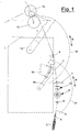
- Figure 1 shows the side view of the run scheme of the yarn in a bobbin winder station 1, whose shape is indicated by the dotted line in its most significant components. Proceeding from the bottom upwards, the station starts with the feeding bobbin 2, from which the yarn 3 is unwound, which rotates as a vortex around the bobbin with a balloon which is controlled through the funnel-shaped balloon breaker 4.
- the yarn 3 passes into the first deviator 5 and to the thread tension device 6, consisting of two opposite rotating disks, which are pressed against each other with an adjustable force.
- the thread tension device 6 the yarn encounters a second deviator 7 before the thread guide plate 8.
- the deviators 5 and 7 consist of two plates with a V-shaped groove for centering the yarn, in which a gasket made of porcelain, or a similar material, is generally inserted, to reduce friction and wear.
- the fluff suppressing device 10 can be inserted between the thread tension device 6 and the second deviator 7. It is described hereunder, with respect to its structure, functioning and components, making reference to figures 2 and 3.
- the thread 3 encounters the thread guide plate 8, the component which detects the yarn defects and activates the organs dedicated to their removal, by cutting and eliminating the faulty pieces, and by joining the resulting yarn ends, in order to continue the processing of the thread after restoring its continuity.
- the spun yarn 3 After passing through the guide plate 8, the spun yarn 3 is wound onto the collecting bobbin 12, which operates resting and rotating on the driving roller 13, which makes the bobbin rotate at a constant linear rate.
- the joining organ of the yarn ends consists of the thread connector 15 shown with a dotted line.
- Said thread connector is served by two mobile mouthpieces for catching and delivering the yarn ends.
- the yarn end catching mouthpiece 16 at the side of the spool 2 can have a bi-directional rotation shown by the arrow A, to catch the yarn end from the side of the feeding spool and direct it to the thread connector 15, with an anticlockwise rotation following the path 17, in the position shown with the dotted line.
- the yarn end catching mouthpiece 18 at the side of the tapered bobbin 12 can have a bi-directional rotation shown by the arrow B, to catch the yarn end from the side of the bobbin produced, in the position shown with the dotted line, and then direct it to the thread connector 15, with a clockwise rotation, following the path 19.
- the objective of the present invention is to provide a device and process for reducing yarn fluff, which overcomes the drawbacks of the yarn fluff reducing devices and processes of the known art and allows yarns to be obtained with reduced fluffing at lower investment and running costs.
- the yarn fluff reducing device according to the invention is defined, in its main components, in the first claim, whereas its variants and preferential embodiments are defined and specified in the dependent claims thereof.
- Said figures refer to an embodiment of the fluff suppressing device, according to the invention, to deliver a thread to the winding tapered bobbin 12, from which most of the fluff has been eliminated, which it would otherwise have at the exit of the spun yarn run described with reference to figure 1.
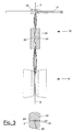
- a typical embodiment of a fluff suppressing device, according to the present invention, is schematically illustrated in figures 2 and 3, in a perspective and front view, respectively.
- Figure 4 illustrates an alternative embodiment of the fluff suppressing device in a different position on the run of the yarn 3 from the pirn to the bobbin.
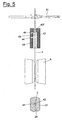
- Figure 5 illustrates a preferential embodiment of the fluff suppressing device, according to the present invention, modified with respect to the previous figure 3.
- the thread guide plate 10 is shown in its main components in figures 2 and 3. In this illustrative embodiment, it is placed in the position shown in figure 1, above the disks of the thread tension device 6 and within the field of action of the mouthpiece 15 for catching the thread at the spool side. In the thread tension device 6, the yarn 3 runs upwards; it is grasped and constrained in the drawing plane of figure 3, but it can move into the plane of the opposite disks of the thread tension device.
- the fluff reducing or suppressing device comprises a nozzle-holding block 21, in which the treatment nozzle 22 is inserted, containing a cylindrical and longitudinal duct 23 into which the spun yarn 3 runs at a high speed.
- the pressure of the service compressed air is generally 1-6 bars and the diameter of the ducts 24 is about 0.5 mm.
- the length of the duct 23 is generally within the range of 8-20 mm.
- the ducts 24 are situated in opposite positions and are tangentially oriented with respect to the longitudinal duct 23, generating an essentially rotational stress on the fibrils protruding from the spun yarn 3 which runs at a high speed inside.
- the air vortex induced by means of the ducts 24 has the same direction as the twist produced on the yarn during its original spinning, so as to twist the protruding fibrils and bring them back into the spun yarns, and not de-twisting, releasing and removing them, as the known technique describes. Only the shortest fibrils, which are not well rooted in the fibrous body of the yarn, can escape as a result of being torn from the yarn.
- the outlets of the ducts 24 are preferably in an orthogonal direction to the duct 23, so as to maximize the rotatory component of the air flow with respect to the axial component.
- a V-shaped slit 28 is made on the front side of block 21, which allows the yarn to enter the duct 23 with the longitudinal slit 29 open and extending along its whole length.
- This inlet is suitable for returning the spun yarn 3 back into the duct 23 during its joining operation in the thread connector 15, so that the yarn is inside the duct 23 after each intervention for eliminating a defect from the spun yarn being processed and when the bobbin winding operation is restarted.
- Another guiding organ 31, for the correct re-entering of the yarn into the slit 29, is situated, at a suitable vertical distance, above the nozzle-holding block 21.
- This guiding organ 31 consists of a widely open slit 32 having at the bottom a gasket 33 made of porcelain or other material, similar to that of the deviators 5 and 7.
- This gasket 33 acts as a guide for the re-entering of the yarn but, once the bobbin winding of the spun yarn has re-established regime conditions, it does not induce any appreciable deviation of the yarn and does not act as a balloon controller or reducer, as in the case of the deviators conceived by the state of the art mentioned above.
- no deviation or control means of the yarn being processed are placed around the device 10.
- a salient feature of the device according to the invention is that the transversal dimension of the -duct- 23 is not much greater than that of the yarn under processing. Generally speaking, the diameter of the duct 23 can range between 5 and 15 times the nominal diameter of the yarn to be processed.
- the stress induced by the compressed air jets introduced by means of the ducts 24, is not sufficient to significantly develop a balloon inside the duct 23: it induces, on the other hand, an air vortex around the yarn which runs without twisting in the same direction as this vortex, or rather without a significant formation of a balloon and without the consequent actions of false twisting mentioned above.
- the fluff reduction action of the yarn is, in fact, more efficient in the absence of the balloon, i.e. when the yarn does not follow a loop course with a rotational motion with respect to the direction of the yarn path, and therefore without moving in concordance with the air vortex which induces it, as happens, on the contrary, with the formation of the balloon.
- the fluff reducing process envisages that the air flow induced by the ducts 24 corresponds to the twist of the yarn under processing, so as to re-twist the protruding fibrils, and lead them back into the yarn, letting, at the most, only the shortest and less rooted fibrils in the fiber body, escape.
- the containment cavity 36 is arranged in the nozzle-holding block 21, in which the nozzle 22 having a duct 23 of a suitable shape and dimension according to the yarn under process, is assembled each time.
- the course of the yarn 3 within the fluff preventing device 10 according to the invention is not subjected to constraints or directional variations in the interval between the deviators 5 and 7, where the device is inserted.
- the stress transmitted to the yarn inside the duct 23, can consequently propagate and be released in the external tracts, both upstream towards the thread tension device 6 and downstream towards the deviator 7, without causing a significant formation and maintenance of the balloon.
- an elongated balloon can be formed, not stable and not very apparent in the two external parts of the nozzle 22, indicatively indicated in figure 3.
- the yarn fluff reducing process according to the present invention therefore consists in passing said spun yarn into the duct 23 of the nozzle 22, at the processing rate, inducing thereon a transversal air flow, causing a vortex having the same rotational direction as the yarn twist, and preventing or limiting the yarn from following a balloon trend, rotating in accordance with the compressed air.
- the air has the maximum relative velocity with respect to the yarn and winds around the central body the part of the fibrils protruding from the same.
- the non-formation or limitation of the balloon is obtained by eliminating, in the device according to the present invention, any significant deviation of the yarn near the fluff preventing device.
- the devices of the known technique develop and blow up the balloon inside the interval delimited by the deviation blocks, pursuing the effects of the false twist -and centrifugal force.
- the -effect of the centrifugal force is in fact harmful, as it extracts the fibers which are not well secured from the central body of the yarn, thus forming further fluffing and tearing away other fluff which causes powder on the machine walls.
- the fluff preventing device is placed in the position indicated in figure 4, in the final straight tract of the course of the yarn 3 above the guide plate 8 and within the field of action of the mouthpiece 18 for the collection of the yarn end from the side of the spool.
- the fluff removal treatment is carried out at the point with the highest output, in the tract where there is the greatest presence of fluff, after the yarn has been subjected to all deviation stress, shocks and scratching and is collected on the bobbin 12.
- Figure 5 shows a preferential embodiment of the fluff preventing device according to the present invention.
- This embodiment envisages the use of a treatment nozzle 42, which contains a cylindrical and longitudinal duct 43 through which the yarn 3 runs upwards at high speed.
- the duct 43 is divided into two coaxial cylindrical tracts 43' and 43" having a different diameter.
- One or more ducts 44, carrying fluid under pressure, run into the first, lower tract 43', which is longer and with greater diameter with respect to the subsequent duct 43", preferably in its upper part and with a direction substantially orthogonal to the thread 3 direction.
- Figure 5 shows two tangential and superimposed ducts 44.
- the second, upper tract 43" with a smaller diameter, restricts the dimension of the yarn 3 passage and its diameter is about 40-90% with respect to the lower tract 43', preferably within the range of 45-65%.
- the length of the upper tract 43" ranges from 10 to 30% of the whole length of the tract 43, whereas the length of the other tract 43' occupies the remaining 70-90% of the overall length.
- This nozzle configuration has proved to be particularly effective in limiting the formation of undesired balloons and in the removal of fluff by rewinding it onto the thread 3.
- the greater dimension of the tract 43' favours the axial discharge of the compressed air from the lower part and allows the action of the air vortex to be effective on the whole length of said tract 43', which is longer, before being discharged outside the duct.
- the discharge hole of the lower duct 44 has a smaller diameter with respect to that of the upper duct 44, in order to reinforce and stabilize the air vortex moving downwards.
- the fluff reducing device of the spun yarns according to the present invention provides a significant progress with respect to the known technique and at least the following aspects deserve particular consideration.
- the device according to the invention does not require any supplementary contacts and sudden direction deviations of the yarn to be established in its run from the spool to the bobbin, which contribute to the formation of fluff.
Landscapes
- Engineering & Computer Science (AREA)
- Textile Engineering (AREA)
- Yarns And Mechanical Finishing Of Yarns Or Ropes (AREA)
- Spinning Or Twisting Of Yarns (AREA)
- Woven Fabrics (AREA)
Claims (12)
- Vorrichtung zur Reduzierung von Fusseln (10) eines gesponnen Garns, zum Einsetzen auf dem Pfad eines Fadens einer Wickelmaschine von einer Zuführungsspule (2) zu einer konischen Spule (12), umfassend einen Halteblock (21) mit einer Einfassungsvertiefung (36), in welche eine Behandlungsdüse (22) eingesetzt ist, wobei die Düse (22) eine longitudinale Führung (23; 43) des prozessierten Garns und einen oder mehrere Luftinjektionsleitungen (24; 44) in einer tangentialen Richtung mit Bezug auf die Garnbewegung in der longitudinalen Führung (23; 43) enthält, wobei die longitudinale Führung (23; 43) entlang ihrer gesamten Länge einen offenen longitudinalen Schlitz (29) umfasst, dadurch gekennzeichnet, dass um die Vorrichtung (10) keine Mittel für eine Ablenkung und Steuerung des Garns (3) eingefügt sind, die longitudinale Führung (23; 43) eine geeignete Form und Größe für das prozessierte Garn aufweist, und die Düse (22) jeweils in dem Halteblock (21) zusammengefügt ist, wobei der Luftfluss mittels der Injektionsleitungen (24; 44) entsprechend zu der Verdrehung des prozessierten Garns herbeigeführt wird.
- Vorrichtung zur Reduzierung von Fusseln eines gesponnenen Garns (3) nach Anspruch 1, dadurch gekennzeichnet, dass die Enden der Injektionsleitungen (24; 44) in einer senkrechten Richtung mit Bezug auf die longitudinale Führung (23; 43) ausgerichtet sind.
- Vorrichtung zur Reduzierung von Fusseln eines gesponnenen Garns (3) nach Anspruch 1, dadurch gekennzeichnet, dass der Durchmesser der longitudinalen Führung (23) im Bereich von fünf bis 15 Mal dem Nominaldurchmesser des zu prozessierenden Garns liegt.
- Vorrichtung zur Reduzierung von Fusseln eines gesponnenen Garns (3) nach Anspruch 1, dadurch gekennzeichnet, dass die Injektionsleitungen (24) mit Bezug auf die longitudinale Führung (23) einander gegenüberliegend und tangential ausgerichtet sind.
- Vorrichtung zur Reduzierung von Fusseln eines gesponnenen Garns (3) nach Anspruch 1, dadurch gekennzeichnet, dass die Injektionsleitungen (44) einander überlagert und tangential mit Bezug auf die longitudinale Führung (43) sind.
- Vorrichtung zur Reduzierung von Fusseln eines gesponnenen Garns (3) nach Anspruch 1, dadurch gekennzeichnet, dass die longitudinale Führung (43) in zwei zylindrische Trakte (43', 43'') mit unterschiedlichem Durchmesser unterteilt ist.
- Vorrichtung zur Reduzierung von Fusseln eines gesponnenen Garns (3) nach Anspruch 6, dadurch gekennzeichnet, dass der zweite Trakt (43") der obere ist, welcher einen Durchmesser aufweist, der gleich 40 bis 90 % des Durchmessers des unteren Trakts (43') ist.
- Vorrichtung zur Reduzierung von Fusseln eines gesponnenen Garns (3) nach Anspruch 7, dadurch gekennzeichnet, dass der zweite Trakt (43") einen Durchmesser aufweist, welcher gleich 45 bis 65 % des Durchmessers des unteren Trakts (43') ist.
- Vorrichtung zur Reduzierung von Fusseln eines gesponnenen Garns (3) nach Anspruch 7, dadurch gekennzeichnet, dass die Länge des oberen Trakts (43") von 10 bis 30 % der Gesamtlänge der Führung (43) ist, während die Länge des unteren Trakts (43') die verbleibenden 70 bis 90 % der Gesamtlänge einnimmt.
- Vorrichtung zur Reduzierung von Fusseln eines gesponnenen Garns (3) nach Anspruch 9, dadurch gekennzeichnet, dass die Injektionsleitungen (44) in dem oberen Teil des unteren Trakts (43') positioniert sind, welcher länger ist und einen größeren Durchmesser aufweist als der obere Trakt (43").
- Vorrichtung zur Reduzierung von Fusseln eines gesponnenen Garns (3) nach Anspruch 1, dadurch gekennzeichnet, dass für einen korrekten Eintritt des Garns in den Schlitz (29) ein Führungselement (31) oberhalb der Düse (22) positioniert ist, welches keine signifikante Ablenkung des Garns herbeiführt, wenn die Wickelspule Regelbedingungen unterliegt.
- Verwendung der Vorrichtung (10) zur Reduzierung von Fusseln eines gesponnenen Garns (3) nach Anspruch 1, wobei die Vorrichtung auf dem Pfad eines Fadens einer Wickelmaschine eingesetzt ist, wobei die Vorrichtung (10) zur Reduzierung von Fusseln in einem abschließenden geraden Trakt des Pfads des Garns (3) und oberhalb einer Fadenführungsplatte (8) positioniert ist.
Applications Claiming Priority (2)
| Application Number | Priority Date | Filing Date | Title |
|---|---|---|---|
| IT000846A ITMI20030846A1 (it) | 2003-04-28 | 2003-04-28 | Dispositivo per ridurre la pelosita' dei filati tessili |
| ITMI20030846 | 2003-04-28 |
Publications (3)
| Publication Number | Publication Date |
|---|---|
| EP1473389A2 EP1473389A2 (de) | 2004-11-03 |
| EP1473389A3 EP1473389A3 (de) | 2005-06-22 |
| EP1473389B1 true EP1473389B1 (de) | 2007-07-18 |
Family
ID=32983211
Family Applications (1)
| Application Number | Title | Priority Date | Filing Date |
|---|---|---|---|
| EP04076216A Expired - Lifetime EP1473389B1 (de) | 2003-04-28 | 2004-04-22 | Vorrichtung zur Reduzierung von Fusseln auf Textilgarnen |
Country Status (6)
| Country | Link |
|---|---|
| US (1) | US7104040B2 (de) |
| EP (1) | EP1473389B1 (de) |
| CN (1) | CN100443645C (de) |
| AT (1) | ATE367464T1 (de) |
| DE (1) | DE602004007574D1 (de) |
| IT (1) | ITMI20030846A1 (de) |
Families Citing this family (16)
| Publication number | Priority date | Publication date | Assignee | Title |
|---|---|---|---|---|
| CN100465362C (zh) * | 2006-04-19 | 2009-03-04 | 东华大学 | 一种络筒用股线加捻装置及股线加工方法 |
| CN102154748B (zh) * | 2011-04-11 | 2012-07-18 | 东华大学 | 一种强捻纯棉纱线的加工方法 |
| CN102995192B (zh) * | 2012-12-24 | 2016-01-13 | 江南大学 | 一种湿热定捻系统 |
| JP2014125714A (ja) * | 2012-12-27 | 2014-07-07 | Murata Mach Ltd | 紡績機 |
| CN103510231B (zh) * | 2013-09-25 | 2016-08-17 | 吴江唯奇布业有限公司 | 一种络筒纱线毛羽减少装置 |
| CN105274675B (zh) * | 2015-10-26 | 2017-10-20 | 武汉纺织大学 | 一种定向伸展协同柔化缠绕纱线毛羽的方法 |
| CN105274695B (zh) * | 2015-10-26 | 2017-08-04 | 武汉纺织大学 | 一种多毛羽纱线的超光洁整经方法 |
| CN105274723B (zh) * | 2015-10-26 | 2017-03-29 | 武汉纺织大学 | 一种多毛羽纱线的超光洁纬编针织方法 |
| US10570533B1 (en) * | 2016-11-21 | 2020-02-25 | American Linc, Llc | Safety guard for textile machines |
| CN112224991B (zh) * | 2020-10-29 | 2022-05-27 | 衡阳新新纺织机械有限公司 | 一种纱线络筒加工的灵活型清纱装置 |
| ES1263679Y (es) * | 2020-11-10 | 2021-06-15 | Twistperfect S L | Maquina de hilado y/o torcido de hilos |
| CN113023489B (zh) * | 2021-02-26 | 2022-10-21 | 中山辰元纺织科技有限公司 | 一种槽筒式松式络筒机 |
| CN113832579A (zh) * | 2021-09-01 | 2021-12-24 | 浙江常鑫纺织品有限公司 | 一种环保再生高弹阳涤复合丝生产加捻工艺 |
| CN116330611A (zh) * | 2023-04-19 | 2023-06-27 | 佛山市摩力克家居布业有限公司 | 一种抗老化窗帘生产装置及方法 |
| CN116835382B (zh) * | 2023-09-01 | 2023-11-03 | 常州虹纬纺织有限公司 | 一种包芯纱缠绕收卷装置及其工作方法 |
| CN118274403B (zh) * | 2024-05-31 | 2024-10-01 | 江苏尚福建设工程有限公司 | 一种净化车间用高效过滤装置 |
Family Cites Families (7)
| Publication number | Priority date | Publication date | Assignee | Title |
|---|---|---|---|---|
| US3448570A (en) * | 1968-01-02 | 1969-06-10 | Phillips Petroleum Co | Method and apparatus for taking-up yarn |
| US4858288A (en) * | 1985-04-02 | 1989-08-22 | Burlington Industries, Inc. | Method vortex action yarn hairiness reduction |
| US4624102A (en) * | 1985-06-24 | 1986-11-25 | E. I. Du Pont De Nemours And Company | Method for reducing broken fibers on the surface of a carbon fiber yarn bundle |
| US5263311A (en) * | 1989-09-08 | 1993-11-23 | Institute Of Textile Technology | Method and apparatus for modifying spun textile yarn |
| JPH0676175B2 (ja) * | 1990-01-10 | 1994-09-28 | 村田機械株式会社 | 毛羽抑制装置 |
| TW504526B (en) * | 1998-12-25 | 2002-10-01 | Murata Machinery Ltd | Hairiness suppressing device for automatic winder |
| CN1253620C (zh) * | 2002-07-31 | 2006-04-26 | 东华大学 | 带有摩擦包缠管的毛羽减少装置 |
-
2003
- 2003-04-28 IT IT000846A patent/ITMI20030846A1/it unknown
-
2004
- 2004-04-19 US US10/827,735 patent/US7104040B2/en not_active Expired - Fee Related
- 2004-04-22 AT AT04076216T patent/ATE367464T1/de not_active IP Right Cessation
- 2004-04-22 DE DE602004007574T patent/DE602004007574D1/de not_active Expired - Lifetime
- 2004-04-22 EP EP04076216A patent/EP1473389B1/de not_active Expired - Lifetime
- 2004-04-28 CN CNB2004100366762A patent/CN100443645C/zh not_active Expired - Fee Related
Also Published As
| Publication number | Publication date |
|---|---|
| DE602004007574D1 (de) | 2007-08-30 |
| CN1542181A (zh) | 2004-11-03 |
| US20040211858A1 (en) | 2004-10-28 |
| EP1473389A2 (de) | 2004-11-03 |
| EP1473389A3 (de) | 2005-06-22 |
| ITMI20030846A1 (it) | 2004-10-29 |
| CN100443645C (zh) | 2008-12-17 |
| US7104040B2 (en) | 2006-09-12 |
| ATE367464T1 (de) | 2007-08-15 |
Similar Documents
| Publication | Publication Date | Title |
|---|---|---|
| EP1473389B1 (de) | Vorrichtung zur Reduzierung von Fusseln auf Textilgarnen | |
| US4893461A (en) | Process and device for piecing with a spinning device operating with a pneumatic twisting unit | |
| JP5526915B2 (ja) | 空気紡績装置及び紡績機 | |
| CN101994176B (zh) | 纺纱机械 | |
| CN103827365B (zh) | 生产粗纱的粗纱机和拼接纤维棉条的方法 | |
| CN103510200A (zh) | 喷气式纺织机及其运行方法 | |
| JP2011038210A (ja) | 空気紡績装置及びこの空気紡績装置を備える紡績機 | |
| CN106319698B (zh) | 一种用于纺纱机中的纺纱区的方法及纺纱机中的纺纱区 | |
| CN106414290B (zh) | 一种纺织机和用于操作这种纺织机的方法 | |
| CN102733018A (zh) | 生产粗纱的粗纱机 | |
| CN106222819A (zh) | 空气纺纱机的纺纱装置及其运行方法 | |
| EP2369042B1 (de) | Druckluftspinnvorrichtung und Spinnmaschine | |
| JP2017115290A (ja) | 糸スプライシング装置 | |
| EP0072664A1 (de) | Verfahren und Vorrichtung zum Strecken einer Faserlunte | |
| JP5515933B2 (ja) | 空気紡績装置及び紡績機 | |
| EP3792381B1 (de) | Pneumatische spinnvorrichtung und pneumatische spinnmaschine | |
| JPH04163325A (ja) | 紡績装置 | |
| JP3341726B2 (ja) | 紡績装置 | |
| CN105274667B (zh) | 纺织机及纤维除去方法 | |
| JP3885397B2 (ja) | 毛羽伏せ装置 | |
| JP2001139231A (ja) | 毛羽伏せ装置及び自動ワインダ | |
| CN113493950A (zh) | 用于喷气纺纱机的喷丝头的加捻元件以及喷气纺纱机的工作站 | |
| JP2600417B2 (ja) | 紡績装置 | |
| JPH03241017A (ja) | 精紡機 | |
| JP2022097469A (ja) | 空気精紡機の作業ユニットならびに糸ガイド部材 |
Legal Events
| Date | Code | Title | Description |
|---|---|---|---|
| PUAI | Public reference made under article 153(3) epc to a published international application that has entered the european phase |
Free format text: ORIGINAL CODE: 0009012 |
|
| AK | Designated contracting states |
Kind code of ref document: A2 Designated state(s): AT BE BG CH CY CZ DE DK EE ES FI FR GB GR HU IE IT LI LU MC NL PL PT RO SE SI SK TR |
|
| AX | Request for extension of the european patent |
Extension state: AL HR LT LV MK |
|
| PUAL | Search report despatched |
Free format text: ORIGINAL CODE: 0009013 |
|
| AK | Designated contracting states |
Kind code of ref document: A3 Designated state(s): AT BE BG CH CY CZ DE DK EE ES FI FR GB GR HU IE IT LI LU MC NL PL PT RO SE SI SK TR |
|
| AX | Request for extension of the european patent |
Extension state: AL HR LT LV MK |
|
| 17P | Request for examination filed |
Effective date: 20050705 |
|
| AKX | Designation fees paid |
Designated state(s): AT BE BG CH CY CZ DE DK EE ES FI FR GB GR HU IE IT LI LU MC NL PL PT RO SE SI SK TR |
|
| 17Q | First examination report despatched |
Effective date: 20060421 |
|
| GRAP | Despatch of communication of intention to grant a patent |
Free format text: ORIGINAL CODE: EPIDOSNIGR1 |
|
| GRAS | Grant fee paid |
Free format text: ORIGINAL CODE: EPIDOSNIGR3 |
|
| GRAA | (expected) grant |
Free format text: ORIGINAL CODE: 0009210 |
|
| AK | Designated contracting states |
Kind code of ref document: B1 Designated state(s): AT BE BG CH CY CZ DE DK EE ES FI FR GB GR HU IE IT LI LU MC NL PL PT RO SE SI SK TR |
|
| REG | Reference to a national code |
Ref country code: GB Ref legal event code: FG4D |
|
| REG | Reference to a national code |
Ref country code: CH Ref legal event code: EP |
|
| REF | Corresponds to: |
Ref document number: 602004007574 Country of ref document: DE Date of ref document: 20070830 Kind code of ref document: P |
|
| REG | Reference to a national code |
Ref country code: IE Ref legal event code: FG4D |
|
| PG25 | Lapsed in a contracting state [announced via postgrant information from national office to epo] |
Ref country code: BG Free format text: LAPSE BECAUSE OF FAILURE TO SUBMIT A TRANSLATION OF THE DESCRIPTION OR TO PAY THE FEE WITHIN THE PRESCRIBED TIME-LIMIT Effective date: 20071018 Ref country code: FI Free format text: LAPSE BECAUSE OF FAILURE TO SUBMIT A TRANSLATION OF THE DESCRIPTION OR TO PAY THE FEE WITHIN THE PRESCRIBED TIME-LIMIT Effective date: 20070718 Ref country code: ES Free format text: LAPSE BECAUSE OF FAILURE TO SUBMIT A TRANSLATION OF THE DESCRIPTION OR TO PAY THE FEE WITHIN THE PRESCRIBED TIME-LIMIT Effective date: 20071029 Ref country code: PT Free format text: LAPSE BECAUSE OF FAILURE TO SUBMIT A TRANSLATION OF THE DESCRIPTION OR TO PAY THE FEE WITHIN THE PRESCRIBED TIME-LIMIT Effective date: 20071218 Ref country code: NL Free format text: LAPSE BECAUSE OF FAILURE TO SUBMIT A TRANSLATION OF THE DESCRIPTION OR TO PAY THE FEE WITHIN THE PRESCRIBED TIME-LIMIT Effective date: 20070718 |
|
| REG | Reference to a national code |
Ref country code: CH Ref legal event code: PL |
|
| NLV1 | Nl: lapsed or annulled due to failure to fulfill the requirements of art. 29p and 29m of the patents act | ||
| PG25 | Lapsed in a contracting state [announced via postgrant information from national office to epo] |
Ref country code: AT Free format text: LAPSE BECAUSE OF FAILURE TO SUBMIT A TRANSLATION OF THE DESCRIPTION OR TO PAY THE FEE WITHIN THE PRESCRIBED TIME-LIMIT Effective date: 20070718 Ref country code: PL Free format text: LAPSE BECAUSE OF FAILURE TO SUBMIT A TRANSLATION OF THE DESCRIPTION OR TO PAY THE FEE WITHIN THE PRESCRIBED TIME-LIMIT Effective date: 20070718 Ref country code: CH Free format text: LAPSE BECAUSE OF FAILURE TO SUBMIT A TRANSLATION OF THE DESCRIPTION OR TO PAY THE FEE WITHIN THE PRESCRIBED TIME-LIMIT Effective date: 20070718 Ref country code: LI Free format text: LAPSE BECAUSE OF FAILURE TO SUBMIT A TRANSLATION OF THE DESCRIPTION OR TO PAY THE FEE WITHIN THE PRESCRIBED TIME-LIMIT Effective date: 20070718 |
|
| EN | Fr: translation not filed | ||
| PG25 | Lapsed in a contracting state [announced via postgrant information from national office to epo] |
Ref country code: BE Free format text: LAPSE BECAUSE OF FAILURE TO SUBMIT A TRANSLATION OF THE DESCRIPTION OR TO PAY THE FEE WITHIN THE PRESCRIBED TIME-LIMIT Effective date: 20070718 |
|
| PG25 | Lapsed in a contracting state [announced via postgrant information from national office to epo] |
Ref country code: GR Free format text: LAPSE BECAUSE OF FAILURE TO SUBMIT A TRANSLATION OF THE DESCRIPTION OR TO PAY THE FEE WITHIN THE PRESCRIBED TIME-LIMIT Effective date: 20071019 Ref country code: DK Free format text: LAPSE BECAUSE OF FAILURE TO SUBMIT A TRANSLATION OF THE DESCRIPTION OR TO PAY THE FEE WITHIN THE PRESCRIBED TIME-LIMIT Effective date: 20070718 |
|
| PLBE | No opposition filed within time limit |
Free format text: ORIGINAL CODE: 0009261 |
|
| STAA | Information on the status of an ep patent application or granted ep patent |
Free format text: STATUS: NO OPPOSITION FILED WITHIN TIME LIMIT |
|
| PG25 | Lapsed in a contracting state [announced via postgrant information from national office to epo] |
Ref country code: SK Free format text: LAPSE BECAUSE OF FAILURE TO SUBMIT A TRANSLATION OF THE DESCRIPTION OR TO PAY THE FEE WITHIN THE PRESCRIBED TIME-LIMIT Effective date: 20070718 Ref country code: CZ Free format text: LAPSE BECAUSE OF FAILURE TO SUBMIT A TRANSLATION OF THE DESCRIPTION OR TO PAY THE FEE WITHIN THE PRESCRIBED TIME-LIMIT Effective date: 20070718 |
|
| 26N | No opposition filed |
Effective date: 20080421 |
|
| PG25 | Lapsed in a contracting state [announced via postgrant information from national office to epo] |
Ref country code: SE Free format text: LAPSE BECAUSE OF FAILURE TO SUBMIT A TRANSLATION OF THE DESCRIPTION OR TO PAY THE FEE WITHIN THE PRESCRIBED TIME-LIMIT Effective date: 20071018 Ref country code: RO Free format text: LAPSE BECAUSE OF FAILURE TO SUBMIT A TRANSLATION OF THE DESCRIPTION OR TO PAY THE FEE WITHIN THE PRESCRIBED TIME-LIMIT Effective date: 20070718 |
|
| PG25 | Lapsed in a contracting state [announced via postgrant information from national office to epo] |
Ref country code: FR Free format text: LAPSE BECAUSE OF FAILURE TO SUBMIT A TRANSLATION OF THE DESCRIPTION OR TO PAY THE FEE WITHIN THE PRESCRIBED TIME-LIMIT Effective date: 20080314 Ref country code: DE Free format text: LAPSE BECAUSE OF FAILURE TO SUBMIT A TRANSLATION OF THE DESCRIPTION OR TO PAY THE FEE WITHIN THE PRESCRIBED TIME-LIMIT Effective date: 20071019 |
|
| PG25 | Lapsed in a contracting state [announced via postgrant information from national office to epo] |
Ref country code: MC Free format text: LAPSE BECAUSE OF NON-PAYMENT OF DUE FEES Effective date: 20080430 |
|
| GBPC | Gb: european patent ceased through non-payment of renewal fee |
Effective date: 20080422 |
|
| PG25 | Lapsed in a contracting state [announced via postgrant information from national office to epo] |
Ref country code: EE Free format text: LAPSE BECAUSE OF FAILURE TO SUBMIT A TRANSLATION OF THE DESCRIPTION OR TO PAY THE FEE WITHIN THE PRESCRIBED TIME-LIMIT Effective date: 20070718 |
|
| PG25 | Lapsed in a contracting state [announced via postgrant information from national office to epo] |
Ref country code: IE Free format text: LAPSE BECAUSE OF NON-PAYMENT OF DUE FEES Effective date: 20080422 |
|
| PG25 | Lapsed in a contracting state [announced via postgrant information from national office to epo] |
Ref country code: GB Free format text: LAPSE BECAUSE OF NON-PAYMENT OF DUE FEES Effective date: 20080422 Ref country code: SI Free format text: LAPSE BECAUSE OF FAILURE TO SUBMIT A TRANSLATION OF THE DESCRIPTION OR TO PAY THE FEE WITHIN THE PRESCRIBED TIME-LIMIT Effective date: 20070718 |
|
| PG25 | Lapsed in a contracting state [announced via postgrant information from national office to epo] |
Ref country code: CY Free format text: LAPSE BECAUSE OF FAILURE TO SUBMIT A TRANSLATION OF THE DESCRIPTION OR TO PAY THE FEE WITHIN THE PRESCRIBED TIME-LIMIT Effective date: 20070718 |
|
| PG25 | Lapsed in a contracting state [announced via postgrant information from national office to epo] |
Ref country code: LU Free format text: LAPSE BECAUSE OF NON-PAYMENT OF DUE FEES Effective date: 20080422 Ref country code: HU Free format text: LAPSE BECAUSE OF FAILURE TO SUBMIT A TRANSLATION OF THE DESCRIPTION OR TO PAY THE FEE WITHIN THE PRESCRIBED TIME-LIMIT Effective date: 20080119 |
|
| PG25 | Lapsed in a contracting state [announced via postgrant information from national office to epo] |
Ref country code: TR Free format text: LAPSE BECAUSE OF NON-PAYMENT OF DUE FEES Effective date: 20100914 |
|
| PG25 | Lapsed in a contracting state [announced via postgrant information from national office to epo] |
Ref country code: TR Free format text: LAPSE BECAUSE OF NON-PAYMENT OF DUE FEES Effective date: 20080422 |
|
| PGFP | Annual fee paid to national office [announced via postgrant information from national office to epo] |
Ref country code: IT Payment date: 20150223 Year of fee payment: 12 |
|
| PG25 | Lapsed in a contracting state [announced via postgrant information from national office to epo] |
Ref country code: IT Free format text: LAPSE BECAUSE OF NON-PAYMENT OF DUE FEES Effective date: 20160422 |